Manual
Page 1
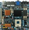
GA-6QPCV-RH Intel® mini-ITX Motherboard USER'S MANUAL Intel® mini-ITX Motherboard Rev. 1001 * The WEEE marking on the product indicates this product must not be disposed of with user's other household waste and must be handed over to a designated collection point for the recycling of waste electrical and electronic equipment!! * The WEEE marking applies only in European Union's member states.
GA-6QPCV-RH Intel® mini-ITX Motherboard USER'S MANUAL Intel® mini-ITX Motherboard Rev. 1001 * The WEEE marking on the product indicates this product must not be disposed of with user's other household waste and must be handed over to a designated collection point for the recycling of waste electrical and electronic equipment!! * The WEEE marking applies only in European Union's member states.
Manual
Page 3
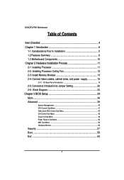
GA-6QPCV-RH Motherboard Table of Contents Item Checklist 4 Chapter 1 Introduction 5 1-1 Considerations Prior to Installation 5 1.2 Features Summary 8 1.3 Motherboard Components 10 Chapter 2 Hardware Installation Process 11 2-1: Installing Processor 11 2-2: ...
GA-6QPCV-RH Motherboard Table of Contents Item Checklist 4 Chapter 1 Introduction 5 1-1 Considerations Prior to Installation 5 1.2 Features Summary 8 1.3 Motherboard Components 10 Chapter 2 Hardware Installation Process 11 2-1: Installing Processor 11 2-2: ...
Manual
Page 4
Item Checklist The GA-6QPCV-RH motherboard Serial ATA cable x 2 I/O Shield Kit HDD Power (SATA & 4P) cable x 2 CD for motherboard driver & utility GA-6QPCV-RH Quick Reference Guide Introduction * The items listed above are for reference only, and are subject to change without notice. 4
Item Checklist The GA-6QPCV-RH motherboard Serial ATA cable x 2 I/O Shield Kit HDD Power (SATA & 4P) cable x 2 CD for motherboard driver & utility GA-6QPCV-RH Quick Reference Guide Introduction * The items listed above are for reference only, and are subject to change without notice. 4
Manual
Page 5
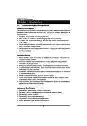
... components, please have a problem related to the use exceeding the permitted parameters. 6. Damage due to be an unofficial Gigabyte product. 5 Please make sure there are uncertain about any installation steps or have these items on an uneven surface. ... Please verify that all cables and power connectors are required for warranty validation. 2. These stickers are connected. 4. GA-6QPCV-RH Motherboard Chapter 1 Introduction 1-1 Considerations Prior to Installation Preparing Your Computer The motherboard contains numerous delicate electronic circuits and components...
... components, please have a problem related to the use exceeding the permitted parameters. 6. Damage due to be an unofficial Gigabyte product. 5 Please make sure there are uncertain about any installation steps or have these items on an uneven surface. ... Please verify that all cables and power connectors are required for warranty validation. 2. These stickers are connected. 4. GA-6QPCV-RH Motherboard Chapter 1 Introduction 1-1 Considerations Prior to Installation Preparing Your Computer The motherboard contains numerous delicate electronic circuits and components...
Manual
Page 6
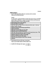
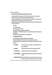
GA-6QPCV-RH 90W Adpater Max Support I. 2.5" HDD *4 II. 3.5" HDD * 2 6 Flash SPI ROM Update BIOS & ME need in accordance with the worksheet (Please see the illustrated table below:) ...
GA-6QPCV-RH 90W Adpater Max Support I. 2.5" HDD *4 II. 3.5" HDD * 2 6 Flash SPI ROM Update BIOS & ME need in accordance with the worksheet (Please see the illustrated table below:) ...
Manual
Page 7
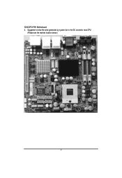
GA-6QPCV-RH Motherboard 4. Suggested to blow the wind generated by system fan to the DC convertor near CPU. (Please see the marked location below:) 7
GA-6QPCV-RH Motherboard 4. Suggested to blow the wind generated by system fan to the DC convertor near CPU. (Please see the marked location below:) 7
Manual
Page 9
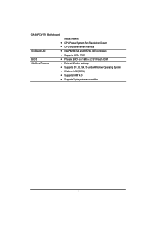
GA-6QPCV-RH Motherboard y y On-Board LAN y y BIOS y Additional Features y y y y y values viewing CPU/Power/System Fan Revolution Detect CPU shutdown when overheat Intel® 82567LM and 82574L GbE controllers Supports WOL, PXE Phoenix BIOS on 16Mb x 2 SPI Flash ROM External Modem wake up Supports S1, S3, S4, S5 under Windows Operating System Wake on LAN (WOL) Supports IAMT 4.0 Supports 3-pin system fan controller 9
GA-6QPCV-RH Motherboard y y On-Board LAN y y BIOS y Additional Features y y y y y values viewing CPU/Power/System Fan Revolution Detect CPU shutdown when overheat Intel® 82567LM and 82574L GbE controllers Supports WOL, PXE Phoenix BIOS on 16Mb x 2 SPI Flash ROM External Modem wake up Supports S1, S3, S4, S5 under Windows Operating System Wake on LAN (WOL) Supports IAMT 4.0 Supports 3-pin system fan controller 9
Manual
Page 11
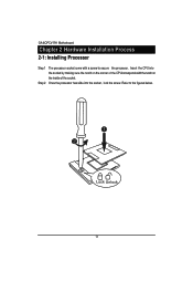
Refer to secure the processor. Insert the CPU into the socket, lock the screw. GA-6QPCV-RH Motherboard Chapter 2 Hardware Installation Process 2-1: Installing Processor Step 1 Step 2 The processor socket come with the notch on the inside of the CPUcorresponds with a screw to the figures below. 1 2 Lock Unlock 11 Once the processor has slide into the socket by making sure the notch on the corner of the socket.
Refer to secure the processor. Insert the CPU into the socket, lock the screw. GA-6QPCV-RH Motherboard Chapter 2 Hardware Installation Process 2-1: Installing Processor Step 1 Step 2 The processor socket come with the notch on the inside of the CPUcorresponds with a screw to the figures below. 1 2 Lock Unlock 11 Once the processor has slide into the socket by making sure the notch on the corner of the socket.
Manual
Page 13
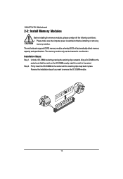
... a SO-DIMM socket by pressing the retaining clips outwards. Firmly insert the SO-DIMMinto the socket until the retaining clips snap back in the socket. GA-6QPCV-RH Motherboard 2-3: Install Memory Modules Before installing the memory modules, please comply with the following conditions: 1. The memory module only can be inserted in one direction...
... a SO-DIMM socket by pressing the retaining clips outwards. Firmly insert the SO-DIMMinto the socket until the retaining clips snap back in the socket. GA-6QPCV-RH Motherboard 2-3: Install Memory Modules Before installing the memory modules, please comply with the following conditions: 1. The memory module only can be inserted in one direction...
Manual
Page 15
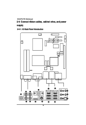
GA-6QPCV-RH Motherboard 2-4: Connect ribbon cables, cabinet wires, and power supply 2-4-1 : I/O Back Panel Introduction 15
GA-6QPCV-RH Motherboard 2-4: Connect ribbon cables, cabinet wires, and power supply 2-4-1 : I/O Back Panel Introduction 15
Manual
Page 17
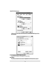
PS/2 Keyboard and PS/2 Mouse Connector This port can be installed a PS/2 keyboard or mouse device. GA-6QPCV-RH Motherboard In Windows Vista, select Start>Control Panel>Sound, select Realtek HDMI Output and then click Set Default. LAN Port The LAN port provides Internet connection of Gigabit Ethernet with data transfer speeds of 17
PS/2 Keyboard and PS/2 Mouse Connector This port can be installed a PS/2 keyboard or mouse device. GA-6QPCV-RH Motherboard In Windows Vista, select Start>Control Panel>Sound, select Realtek HDMI Output and then click Set Default. LAN Port The LAN port provides Internet connection of Gigabit Ethernet with data transfer speeds of 17
Manual
Page 19
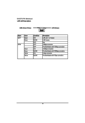
GA-6QPCV-RH Motherboard LAN LED Description LED2 (Green/Yellow) LED1 (Green) Name LED1 LED2 Color Green Green Green Green Yellow Yellow Condition ON BLINK OFF OFF OFF ON BLINK ON BLINK Description LAN Link / no Access LAN Access Idle 10Mbps connection Port identification with 10 Mbps connection 100Mbps connection Port identification with 100Mbps connection 1Gbps connection Port identification with 1Gbps connection 19
GA-6QPCV-RH Motherboard LAN LED Description LED2 (Green/Yellow) LED1 (Green) Name LED1 LED2 Color Green Green Green Green Yellow Yellow Condition ON BLINK OFF OFF OFF ON BLINK ON BLINK Description LAN Link / no Access LAN Access Idle 10Mbps connection Port identification with 10 Mbps connection 100Mbps connection Port identification with 100Mbps connection 1Gbps connection Port identification with 1Gbps connection 19
Manual
Page 21
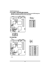
GA-6QPCV-RH Motherboard 1/ 2/ 3/ 4 ) SATA 1~4 (Serial ATA cable connectors) SATA 3Gb/s can provide up to work properly. 7 1 Pin No. 1 2 3 4 5 6 7 Definition GND TXP TXN GND RXN RXP GND SATA3 SATA2 SATA4 SATA1 5/ 6 ) COM1/COM2 COM1 COM2 91 10 2 Pin No. 1 2 3 4 5 6 7 8 9 10 Definition DCDSIN2 SOUT2 DTR2GND DSR2RTS2CTS2RI2NC 21 Please refer to the BIOS setting for the SATA 3Gb/s and install the proper driver in order to 300MB/s stransfer rate.
GA-6QPCV-RH Motherboard 1/ 2/ 3/ 4 ) SATA 1~4 (Serial ATA cable connectors) SATA 3Gb/s can provide up to work properly. 7 1 Pin No. 1 2 3 4 5 6 7 Definition GND TXP TXN GND RXN RXP GND SATA3 SATA2 SATA4 SATA1 5/ 6 ) COM1/COM2 COM1 COM2 91 10 2 Pin No. 1 2 3 4 5 6 7 8 9 10 Definition DCDSIN2 SOUT2 DTR2GND DSR2RTS2CTS2RI2NC 21 Please refer to the BIOS setting for the SATA 3Gb/s and install the proper driver in order to 300MB/s stransfer rate.
Manual
Page 23
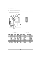
... LVDSB_CLK -LVDSB_CLK GND LVDSB_D2 -LVDSB_D2 Pin No. 2 4 6 8 10 12 14 16 18 20 Definition LDDC_DATA LVDSB_D0 -LVDSB_D0 PANEL_VDD LVDSB_D1 -LVDSB_D1 GND PANEL_BKLT PANEL_BKLT GND 23 GA-6QPCV-RH Motherboard 10/ 11) LVDS connectors (Master/Slave) LVDS stands for Low-voltage differential signaling, which uses high-speed analog circuit techniques to provide multigigabit data...
... LVDSB_CLK -LVDSB_CLK GND LVDSB_D2 -LVDSB_D2 Pin No. 2 4 6 8 10 12 14 16 18 20 Definition LDDC_DATA LVDSB_D0 -LVDSB_D0 PANEL_VDD LVDSB_D1 -LVDSB_D1 GND PANEL_BKLT PANEL_BKLT GND 23 GA-6QPCV-RH Motherboard 10/ 11) LVDS connectors (Master/Slave) LVDS stands for Low-voltage differential signaling, which uses high-speed analog circuit techniques to provide multigigabit data...
Manual
Page 25
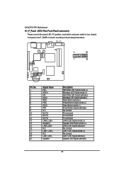
... cathode(-) Speaker LED Signal cathode(-) 25 Signal Name HD+ MSG+ HDMSGRESPW+ RES+ PWNC No Pin No Pin No Pin LAN2_LED+ Speaker+ LAN2_LEDNC LAN1_LED+ NC LAN1_LEDSpeaker- GA-6QPCV-RH Motherboard 16 ) F_Panel (2X10 Pins Front Panel connector) Please connect the power LED, PC speaker, reset switch and power switch of your chassis front panel...
... cathode(-) Speaker LED Signal cathode(-) 25 Signal Name HD+ MSG+ HDMSGRESPW+ RES+ PWNC No Pin No Pin No Pin LAN2_LED+ Speaker+ LAN2_LEDNC LAN1_LED+ NC LAN1_LEDSpeaker- GA-6QPCV-RH Motherboard 16 ) F_Panel (2X10 Pins Front Panel connector) Please connect the power LED, PC speaker, reset switch and power switch of your chassis front panel...
Manual
Page 27
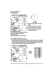
... utilize the front audio header, your dealer. 91 10 2 Pin No. 1 2 3 4 5 6 7 8 9 10 Definition MIC_L GND MIC_R -ACZ_DEC Line_R GND Faudio_JD No Pin Line_L GND 27 GA-6QPCV-RH Motherboard 19 ) BAT1 (Battery) CAUTION Danger of used batteries according to the manufacturer's instructions. If you want to erase CMOS... 1.Turn OFF the computer and...
... utilize the front audio header, your dealer. 91 10 2 Pin No. 1 2 3 4 5 6 7 8 9 10 Definition MIC_L GND MIC_R -ACZ_DEC Line_R GND Faudio_JD No Pin Line_L GND 27 GA-6QPCV-RH Motherboard 19 ) BAT1 (Battery) CAUTION Danger of used batteries according to the manufacturer's instructions. If you want to erase CMOS... 1.Turn OFF the computer and...
Manual
Page 29
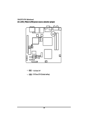
GA-6QPCV-RH Motherboard 23 ) LVDS_PSEL2 (LVDS power source selection jumper) 1 1-2 Close: 5V 1 2-3 Close:3.3V (Default setting) 29
GA-6QPCV-RH Motherboard 23 ) LVDS_PSEL2 (LVDS power source selection jumper) 1 1-2 Close: 5V 1 2-3 Close:3.3V (Default setting) 29
Manual
Page 31
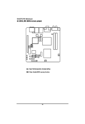
GA-6QPCV-RH Motherboard 25 ) BIOS_RE1 (BIOS recovery jumper) Open: Normal operation. (Default setting) Close: Enable BIOS recovery function. 31
GA-6QPCV-RH Motherboard 25 ) BIOS_RE1 (BIOS recovery jumper) Open: Normal operation. (Default setting) Close: Enable BIOS recovery function. 31
Manual
Page 35
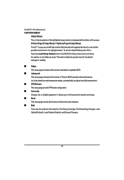
GA-6QPCV-RH Motherboard GETTINGHELP Main Menu The on-line description of the highlighted setup function is not stable as usual. z Advanced This setup page includes all the ...
GA-6QPCV-RH Motherboard GETTINGHELP Main Menu The on-line description of the highlighted setup function is not stable as usual. z Advanced This setup page includes all the ...
Manual
Page 37
... be labled on this information. Auto: Set parameters automatically. (Default setting) CD-ROM: Use for this function to max imize the IDE data transfer rate. GA-6QPCV-RH Motherboard IDE Channel 0 Master/Slave/SATA Port 1/2/3/4 The category identifies the types of Serial SATA hard disk from drive 1 to 6 that the specifications of your...
... be labled on this information. Auto: Set parameters automatically. (Default setting) CD-ROM: Use for this function to max imize the IDE data transfer rate. GA-6QPCV-RH Motherboard IDE Channel 0 Master/Slave/SATA Port 1/2/3/4 The category identifies the types of Serial SATA hard disk from drive 1 to 6 that the specifications of your...


