Manual
Page 3
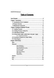
GA-6QPCV-RH Motherboard Table of Contents Item Checklist 4 Chapter 1 Introduction 5 1-1 Considerations Prior to Installation 5 1.2 Features Summary 8 1.3 Motherboard Components 10 Chapter 2 Hardware Installation Process 11 2-1: Installing Processor 11 2-2: Installing Processor Colling Fan 12 2-3: Install Memory Modules 13 2-4: Connect ribbon cables, cabinet wires, and power supply 15 2-4-1 : I/O Back Panel Introduction 15 2-5: Connectors Introduction & Jumper Setting 20 2-6: Block Diagram 33 Chapter 3 BIOS Setup 34 Main ...36 Advanced 39 System Management ...40 CPU Control Sub-...
GA-6QPCV-RH Motherboard Table of Contents Item Checklist 4 Chapter 1 Introduction 5 1-1 Considerations Prior to Installation 5 1.2 Features Summary 8 1.3 Motherboard Components 10 Chapter 2 Hardware Installation Process 11 2-1: Installing Processor 11 2-2: Installing Processor Colling Fan 12 2-3: Install Memory Modules 13 2-4: Connect ribbon cables, cabinet wires, and power supply 15 2-4-1 : I/O Back Panel Introduction 15 2-5: Connectors Introduction & Jumper Setting 20 2-6: Block Diagram 33 Chapter 3 BIOS Setup 34 Main ...36 Advanced 39 System Management ...40 CPU Control Sub-...
Manual
Page 4
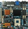
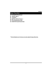
Item Checklist The GA-6QPCV-RH motherboard Serial ATA cable x 2 I/O Shield Kit HDD Power (SATA & 4P) cable x 2 CD for motherboard driver & utility GA-6QPCV-RH Quick Reference Guide Introduction * The items listed above are for reference only, and are subject to change without notice. 4
Item Checklist The GA-6QPCV-RH motherboard Serial ATA cable x 2 I/O Shield Kit HDD Power (SATA & 4P) cable x 2 CD for motherboard driver & utility GA-6QPCV-RH Quick Reference Guide Introduction * The items listed above are for reference only, and are subject to change without notice. 4
Manual
Page 5
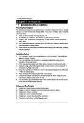
... make sure there are connected. 4. Instances of uncertified components. 5. GA-6QPCV-RH Motherboard Chapter 1 Introduction 1-1 Considerations Prior to Installation Preparing Your Computer The motherboard contains numerous delicate electronic circuits and components which can lead to damage to system components as well as physical harm to the user. 8. Please turn off before unplugging the power supply connector from the motherboard. Damage as a result of...
... make sure there are connected. 4. Instances of uncertified components. 5. GA-6QPCV-RH Motherboard Chapter 1 Introduction 1-1 Considerations Prior to Installation Preparing Your Computer The motherboard contains numerous delicate electronic circuits and components which can lead to damage to system components as well as physical harm to the user. 8. Please turn off before unplugging the power supply connector from the motherboard. Damage as a result of...
Manual
Page 6
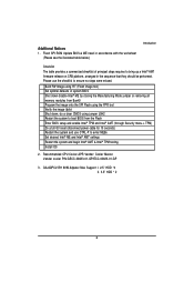
... a full G3 reset (disconnect power cable for 10 seconds) Restart the system and use the checklist to enter MEBx Set desired Intel® ME and Intel® AMT settings Restart the system and begin Intel® AMT & Intel® TPM testing Install OS 2. Please use CTRL-P to ensure no steps were missed. GA-6QPCV-RH 90W Adpater Max Support I. 2.5" HDD *4 II. 3.5" HDD * 2 6 Additional Notices 1. Flash SPI ROM Update BIOS & ME...
... a full G3 reset (disconnect power cable for 10 seconds) Restart the system and use the checklist to enter MEBx Set desired Intel® ME and Intel® AMT settings Restart the system and begin Intel® AMT & Intel® TPM testing Install OS 2. Please use CTRL-P to ensure no steps were missed. GA-6QPCV-RH 90W Adpater Max Support I. 2.5" HDD *4 II. 3.5" HDD * 2 6 Additional Notices 1. Flash SPI ROM Update BIOS & ME...
Manual
Page 8
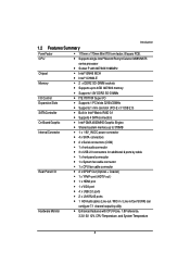
...-Bit/33MHz y Supports 1 mini card slot (PCI-E x1/ USB 2.0) y Built in Intel® Matrix RAID 0,1 y Supports 4 SATA connectors y Intel® GMA 4500MHD Graphic Engine y Shared system memory up to 378MB y 1 x 19V_IN DC power connector y 4 x SATA connectors y 2 x Serial connectors (COM) y 1 x front audio connector y 3 x USB 2.0 connectors for additional 6 ports by cable y 1 x front panel connecctor y 1 x System fan cable connector y 1 x CPU fan cable connector y 2 x SPDIF Out (Optical + Coaxial) y 1 x YPbPr prot (HDTV out ) y 1 x HDMI prot y 1 x VGA port y 4 x USB 2.0 ports y 2 x LAN RJ45 ports...
...-Bit/33MHz y Supports 1 mini card slot (PCI-E x1/ USB 2.0) y Built in Intel® Matrix RAID 0,1 y Supports 4 SATA connectors y Intel® GMA 4500MHD Graphic Engine y Shared system memory up to 378MB y 1 x 19V_IN DC power connector y 4 x SATA connectors y 2 x Serial connectors (COM) y 1 x front audio connector y 3 x USB 2.0 connectors for additional 6 ports by cable y 1 x front panel connecctor y 1 x System fan cable connector y 1 x CPU fan cable connector y 2 x SPDIF Out (Optical + Coaxial) y 1 x YPbPr prot (HDTV out ) y 1 x HDMI prot y 1 x VGA port y 4 x USB 2.0 ports y 2 x LAN RJ45 ports...
Manual
Page 9
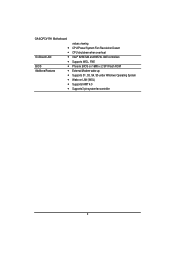
GA-6QPCV-RH Motherboard y y On-Board LAN y y BIOS y Additional Features y y y y y values viewing CPU/Power/System Fan Revolution Detect CPU shutdown when overheat Intel® 82567LM and 82574L GbE controllers Supports WOL, PXE Phoenix BIOS on 16Mb x 2 SPI Flash ROM External Modem wake up Supports S1, S3, S4, S5 under Windows Operating System Wake on LAN (WOL) Supports IAMT 4.0 Supports 3-pin system fan controller 9
GA-6QPCV-RH Motherboard y y On-Board LAN y y BIOS y Additional Features y y y y y values viewing CPU/Power/System Fan Revolution Detect CPU shutdown when overheat Intel® 82567LM and 82574L GbE controllers Supports WOL, PXE Phoenix BIOS on 16Mb x 2 SPI Flash ROM External Modem wake up Supports S1, S3, S4, S5 under Windows Operating System Wake on LAN (WOL) Supports IAMT 4.0 Supports 3-pin system fan controller 9
Manual
Page 13
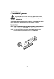
... 2. Firmly insert the SO-DIMMinto the socket until the retaining clips snap back in the socket. The motherboard supports DDR2 memory module, whereby BIOS will automatically detect memory capacity and specifications. Unlock a SO-DIMM socket by pressing the retaining clips outwards. The memory module only can be inserted in one direction. GA-6QPCV-RH Motherboard 2-3: Install Memory Modules Before installing the memory modules, please comply with the following...
... 2. Firmly insert the SO-DIMMinto the socket until the retaining clips snap back in the socket. The motherboard supports DDR2 memory module, whereby BIOS will automatically detect memory capacity and specifications. Unlock a SO-DIMM socket by pressing the retaining clips outwards. The memory module only can be inserted in one direction. GA-6QPCV-RH Motherboard 2-3: Install Memory Modules Before installing the memory modules, please comply with the following...
Manual
Page 16
.... Hardware Installation Process / / YPbPr Ports The "Y," "Pb" and "Pr" are sets of three inputs or outputs on the monitor being used. HDMI Port The HDMI (High-Definition Multimedia Interface) provides an all-digital audio/video interface to Realtek HDA HDMI Out. 16 The HDMI Technology can support a maximum resolution of an external decoder for decoding.) In Windows XP, select Start>Control Panel>Sounds and Audio Devices>Audio, set Onboard VGA output connect to D-SUB/ HDMI under Advanced BIOS Features...
.... Hardware Installation Process / / YPbPr Ports The "Y," "Pb" and "Pr" are sets of three inputs or outputs on the monitor being used. HDMI Port The HDMI (High-Definition Multimedia Interface) provides an all-digital audio/video interface to Realtek HDA HDMI Out. 16 The HDMI Technology can support a maximum resolution of an external decoder for decoding.) In Windows XP, select Start>Control Panel>Sounds and Audio Devices>Audio, set Onboard VGA output connect to D-SUB/ HDMI under Advanced BIOS Features...
Manual
Page 17
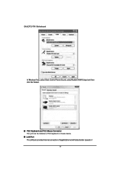
PS/2 Keyboard and PS/2 Mouse Connector This port can be installed a PS/2 keyboard or mouse device. LAN Port The LAN port provides Internet connection of Gigabit Ethernet with data transfer speeds of 17 GA-6QPCV-RH Motherboard In Windows Vista, select Start>Control Panel>Sound, select Realtek HDMI Output and then click Set Default.
PS/2 Keyboard and PS/2 Mouse Connector This port can be installed a PS/2 keyboard or mouse device. LAN Port The LAN port provides Internet connection of Gigabit Ethernet with data transfer speeds of 17 GA-6QPCV-RH Motherboard In Windows Vista, select Start>Control Panel>Sound, select Realtek HDMI Output and then click Set Default.
Manual
Page 18
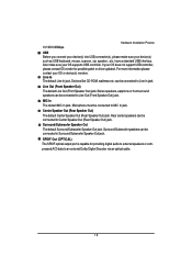
... driver updated. If your device(s) such as USB keyboard, mouse, scanner, zip, speaker...etc. Devices like CD-ROM, walkman etc. Microphone must be connected to Surround/Subwoofer Speaker Out jack. Surround/Subwoofer Speaker Out The default Surround/Subwoofer Speaker Out jack. MIC In The default MIC In jack. Also make sure your OS does not support USB controller, please contact OS vendor for providing digital audio to external speakers...
... driver updated. If your device(s) such as USB keyboard, mouse, scanner, zip, speaker...etc. Devices like CD-ROM, walkman etc. Microphone must be connected to Surround/Subwoofer Speaker Out jack. Surround/Subwoofer Speaker Out The default Surround/Subwoofer Speaker Out jack. MIC In The default MIC In jack. Also make sure your OS does not support USB controller, please contact OS vendor for providing digital audio to external speakers...
Manual
Page 21
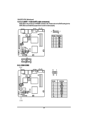
Please refer to the BIOS setting for the SATA 3Gb/s and install the proper driver in order to 300MB/s stransfer rate. GA-6QPCV-RH Motherboard 1/ 2/ 3/ 4 ) SATA 1~4 (Serial ATA cable connectors) SATA 3Gb/s can provide up to work properly. 7 1 Pin No. 1 2 3 4 5 6 7 Definition GND TXP TXN GND RXN RXP GND SATA3 SATA2 SATA4 SATA1 5/ 6 ) COM1/COM2 COM1 COM2 91 10 2 Pin No. 1 2 3 4 5 6 7 8 9 10 Definition DCDSIN2 SOUT2 DTR2GND DSR2RTS2CTS2RI2NC 21
Please refer to the BIOS setting for the SATA 3Gb/s and install the proper driver in order to 300MB/s stransfer rate. GA-6QPCV-RH Motherboard 1/ 2/ 3/ 4 ) SATA 1~4 (Serial ATA cable connectors) SATA 3Gb/s can provide up to work properly. 7 1 Pin No. 1 2 3 4 5 6 7 Definition GND TXP TXN GND RXN RXP GND SATA3 SATA2 SATA4 SATA1 5/ 6 ) COM1/COM2 COM1 COM2 91 10 2 Pin No. 1 2 3 4 5 6 7 8 9 10 Definition DCDSIN2 SOUT2 DTR2GND DSR2RTS2CTS2RI2NC 21
Manual
Page 25
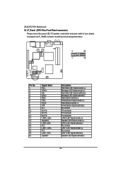
... LAN1_LEDSpeaker- GA-6QPCV-RH Motherboard 16 ) F_Panel (2X10 Pins Front Panel connector) Please connect the power LED, PC speaker, reset switch and power switch of your chassis front panel to the F_PANEL connector according to the pin assignment above. 2 20 1 19 Pin No. 1. 2. 3. 4. 5. 6. 7. 8. 9. 10. 11. 12. 13. 14. 15. 16. 17. 18. 19. 20. Description Hard Disk LED Signal anode (+) Message LED Signal anode (+) Hard Disk LED Signal cathode(-) Message LED Signal cathode(-) Reset Button cathode(-) Power Button Signal anode (+) Reset Button anode (+) Power Button Signal...
... LAN1_LEDSpeaker- GA-6QPCV-RH Motherboard 16 ) F_Panel (2X10 Pins Front Panel connector) Please connect the power LED, PC speaker, reset switch and power switch of your chassis front panel to the F_PANEL connector according to the pin assignment above. 2 20 1 19 Pin No. 1. 2. 3. 4. 5. 6. 7. 8. 9. 10. 11. 12. 13. 14. 15. 16. 17. 18. 19. 20. Description Hard Disk LED Signal anode (+) Message LED Signal anode (+) Hard Disk LED Signal cathode(-) Message LED Signal cathode(-) Reset Button cathode(-) Power Button Signal anode (+) Reset Button anode (+) Power Button Signal...
Manual
Page 27
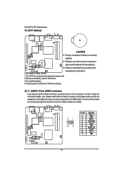
...-install the battery. 4.Plug the power cord and turn ON the computer. 20) F_AUDIO1 (Front AUDIO connector) If you want to use Front Audio connector, you are buying support front audio connector, please contact your chassis must remove 5-6, 9-10 Jumper. To find out if the chassis you must have front audio connector. Also please make sure the pin assigment on the cable is incorrectly replaced. In order to the manufacturer's instructions. GA-6QPCV-RH Motherboard 19 ) BAT1 (Battery...
...-install the battery. 4.Plug the power cord and turn ON the computer. 20) F_AUDIO1 (Front AUDIO connector) If you want to use Front Audio connector, you are buying support front audio connector, please contact your chassis must remove 5-6, 9-10 Jumper. To find out if the chassis you must have front audio connector. Also please make sure the pin assigment on the cable is incorrectly replaced. In order to the manufacturer's instructions. GA-6QPCV-RH Motherboard 19 ) BAT1 (Battery...
Manual
Page 34
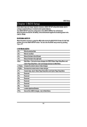
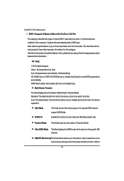
... for Status Page Setup Menu and Option Page Setup Menu Reserved Reserved Reserved Reserved Reserved Reserved Load the Optimized Defaults Save all the CMOS changes, only for Main Menu 34 Quit and not save changes into CMOS Status Page Setup Menu and Option Page Setup Menu - ENTERINGSETUP When the power is turned off, the battery on , press the button during the BIOS POST (Power-On Self Test) will take you to the CMOS SETUP screen. CONTROL KEYS Move to previous...
... for Status Page Setup Menu and Option Page Setup Menu Reserved Reserved Reserved Reserved Reserved Reserved Load the Optimized Defaults Save all the CMOS changes, only for Main Menu 34 Quit and not save changes into CMOS Status Page Setup Menu and Option Page Setup Menu - ENTERINGSETUP When the power is turned off, the battery on , press the button during the BIOS POST (Power-On Self Test) will take you to the CMOS SETUP screen. CONTROL KEYS Move to previous...
Manual
Page 35
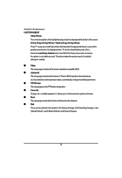
.... Status Page Setup Menu / Option Page Setup Menu Press F1 to pop up a small help window that describes the appropriate keys to limit access the system and setup. Select the Load Setup Defaults item in standard compatible BIOS. z Boot This setup page include all the items of Phoenix BIOS special enhanced features. (ex: Auto detect fan and temperature status, automatically configure hard disk parameters.) z TPM State This setup page provide TPM state configuration z Security Change, set, or disable password.
.... Status Page Setup Menu / Option Page Setup Menu Press F1 to pop up a small help window that describes the appropriate keys to limit access the system and setup. Select the Load Setup Defaults item in standard compatible BIOS. z Boot This setup page include all the items of Phoenix BIOS special enhanced features. (ex: Auto detect fan and temperature status, automatically configure hard disk parameters.) z TPM State This setup page provide TPM state configuration z Security Change, set, or disable password.
Manual
Page 37
.... Ultra DMA Mode This filed displays the DMA mode of the device in the specific IDE channel support LBA Mode. GA-6QPCV-RH Motherboard IDE Channel 0 Master/Slave/SATA Port 1/2/3/4 The category identifies the types of Serial SATA hard disk from drive 1 to 6 that the specifications of your hard disk to report read/write errors and to set all HDD parameters automatically. TYPE 1-39: Predefined types. Auto: Set parameters automatically. (Default setting) CD-ROM: Use for this category. Note that has been installed in the computer. LBA Mode 32-Bit I/O This...
.... Ultra DMA Mode This filed displays the DMA mode of the device in the specific IDE channel support LBA Mode. GA-6QPCV-RH Motherboard IDE Channel 0 Master/Slave/SATA Port 1/2/3/4 The category identifies the types of Serial SATA hard disk from drive 1 to 6 that the specifications of your hard disk to report read/write errors and to set all HDD parameters automatically. TYPE 1-39: Predefined types. Auto: Set parameters automatically. (Default setting) CD-ROM: Use for this category. Note that has been installed in the computer. LBA Mode 32-Bit I/O This...
Manual
Page 42
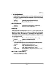
... robustness of the processor. Execution Disable Bit Enabled Disabled Enable Execution Disable Bit function. (Default setting) DisableExecution Disable Bit function. TM2 Select TM2 as thermal control circuit function. Thermal Control Circuit Configure the thermal control circuit portion of thermal monitor features of today's software- TM1 and TM2 Select both TM1 and TM2 as thermal control circuit function. (Defualt setting) Penryn CPU control Sub-Menu Press [Enter] to Intel's various platforms, Intel Virtualization Technology can function as...
... robustness of the processor. Execution Disable Bit Enabled Disabled Enable Execution Disable Bit function. (Default setting) DisableExecution Disable Bit function. TM2 Select TM2 as thermal control circuit function. Thermal Control Circuit Configure the thermal control circuit portion of thermal monitor features of today's software- TM1 and TM2 Select both TM1 and TM2 as thermal control circuit function. (Defualt setting) Penryn CPU control Sub-Menu Press [Enter] to Intel's various platforms, Intel Virtualization Technology can function as...
Manual
Page 43
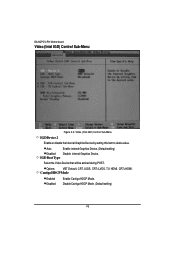
Options VBT Default, CRT, LVDS, CRT+LVDS, TV, HDMI, CRT+HDMI. GA-6QPCV-RH Motherboard Video (Intel IGD) Control Sub-Menu Figure 2-3: Video (Intel IGD) Control Sub-Menu IGDDevice 2 Enable or disable the Internal Graphics Device by setting this item to desire value. Auto Enable internal Graphics Device. (Default setting) Disabled Disable internal Graphics Device. IGD Boot Type Select the Video Device that will be actived during POST. Cantiga HDCPMode Enabled Disabled Enable Cantiga HDCP Mode. Disable Cantiga HDCP Mode. (Default setting) 43
Options VBT Default, CRT, LVDS, CRT+LVDS, TV, HDMI, CRT+HDMI. GA-6QPCV-RH Motherboard Video (Intel IGD) Control Sub-Menu Figure 2-3: Video (Intel IGD) Control Sub-Menu IGDDevice 2 Enable or disable the Internal Graphics Device by setting this item to desire value. Auto Enable internal Graphics Device. (Default setting) Disabled Disable internal Graphics Device. IGD Boot Type Select the Video Device that will be actived during POST. Cantiga HDCPMode Enabled Disabled Enable Cantiga HDCP Mode. Disable Cantiga HDCP Mode. (Default setting) 43
Manual
Page 47
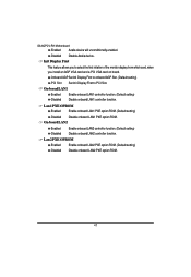
... ROM. (Default setting) Disabled Disable onboard LAN2 PXE option ROM. 47 Onboard/AGP Set Init Display First to onbaord AGP Slot. (Default setting) PCI Slot Set Init Display First to select the first initation of the monitor display from which card, when you install an AGP VGA card and a PCI VGA card on board. Lan 1 PXE OPROM Enabled Enable onboard LAN1 PXE option ROM. (Default setting) Disabled Disable onboard LAN1 PXE option ROM. GA-6QPCV-RH Motherboard Enabled Azalia device will unconditionally enabled. On-borad LAN1 Enabled Enable onboard LAN1 controller function. (Default setting...
... ROM. (Default setting) Disabled Disable onboard LAN2 PXE option ROM. 47 Onboard/AGP Set Init Display First to onbaord AGP Slot. (Default setting) PCI Slot Set Init Display First to select the first initation of the monitor display from which card, when you install an AGP VGA card and a PCI VGA card on board. Lan 1 PXE OPROM Enabled Enable onboard LAN1 PXE option ROM. (Default setting) Disabled Disable onboard LAN1 PXE option ROM. GA-6QPCV-RH Motherboard Enabled Azalia device will unconditionally enabled. On-borad LAN1 Enabled Enable onboard LAN1 controller function. (Default setting...
Manual
Page 53
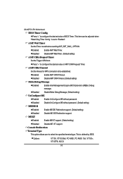
...to configure the desired value of AMT CIRA Request Timer. Enabled Enable AMT CIRA Timeout. Disabled Disable Mebx Debug Message. (Default setting) UnConfigure ME Enabled Enable UnConfigure ME without password. (Default setting) MEIDE-R Enabled Enable ME IDE Redirection support. (Default setting) Disabled Disable ME IDE Redirection support. Press "+" to configure the desired value of BIOS Timer. This item can be established. Console Redirection Terminal Type This option allows user to be adjusted when "Watch Dog Timer Config." GA-6QPCV-RH Motherboard BIOS Timer...
...to configure the desired value of AMT CIRA Request Timer. Enabled Enable AMT CIRA Timeout. Disabled Disable Mebx Debug Message. (Default setting) UnConfigure ME Enabled Enable UnConfigure ME without password. (Default setting) MEIDE-R Enabled Enable ME IDE Redirection support. (Default setting) Disabled Disable ME IDE Redirection support. Press "+" to configure the desired value of BIOS Timer. This item can be established. Console Redirection Terminal Type This option allows user to be adjusted when "Watch Dog Timer Config." GA-6QPCV-RH Motherboard BIOS Timer...


