Manual
Page 1
GA-6QPCV-RH Intel® mini-ITX Motherboard USER'S MANUAL Intel® mini-ITX Motherboard Rev. 1001 * The WEEE marking on the product indicates this product must not be disposed of with user's other household waste and must be handed over to a designated collection point for the recycling of waste electrical and electronic equipment!! * The WEEE marking applies only in European Union's member states.
GA-6QPCV-RH Intel® mini-ITX Motherboard USER'S MANUAL Intel® mini-ITX Motherboard Rev. 1001 * The WEEE marking on the product indicates this product must not be disposed of with user's other household waste and must be handed over to a designated collection point for the recycling of waste electrical and electronic equipment!! * The WEEE marking applies only in European Union's member states.
Manual
Page 2
... copied, translated, or transmitted in any form or by any means without prior notice. For more product details, please click onto Gigabyte's website at www.gigabyte.com.tw Copyright © 2007 GIGA-BYTE TECHNOLOGY CO., LTD. For detailed information related to... Gigabyte's unique features, please go to "Technology Guide" section on Gigabyte's website to assist in the use of Gigabyte. Product Manual Classification In order to read the "Product User Manual". All rights reserved. The ...
... copied, translated, or transmitted in any form or by any means without prior notice. For more product details, please click onto Gigabyte's website at www.gigabyte.com.tw Copyright © 2007 GIGA-BYTE TECHNOLOGY CO., LTD. For detailed information related to... Gigabyte's unique features, please go to "Technology Guide" section on Gigabyte's website to assist in the use of Gigabyte. Product Manual Classification In order to read the "Product User Manual". All rights reserved. The ...
Manual
Page 3
GA-6QPCV-RH Motherboard Table of Contents Item Checklist 4 Chapter 1 Introduction 5 1-1 Considerations Prior to Installation 5 1.2 Features Summary 8 1.3 Motherboard Components 10 Chapter 2 Hardware Installation Process 11 2-1: Installing Processor 11 2-2: ...
GA-6QPCV-RH Motherboard Table of Contents Item Checklist 4 Chapter 1 Introduction 5 1-1 Considerations Prior to Installation 5 1.2 Features Summary 8 1.3 Motherboard Components 10 Chapter 2 Hardware Installation Process 11 2-1: Installing Processor 11 2-2: ...
Manual
Page 4
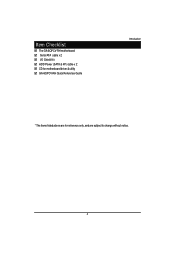
Item Checklist The GA-6QPCV-RH motherboard Serial ATA cable x 2 I/O Shield Kit HDD Power (SATA & 4P) cable x 2 CD for motherboard driver & utility GA-6QPCV-RH Quick Reference Guide Introduction * The items listed above are for reference only, and are subject to change without notice. 4
Item Checklist The GA-6QPCV-RH motherboard Serial ATA cable x 2 I/O Shield Kit HDD Power (SATA & 4P) cable x 2 CD for motherboard driver & utility GA-6QPCV-RH Quick Reference Guide Introduction * The items listed above are for reference only, and are subject to change without notice. 4
Manual
Page 5
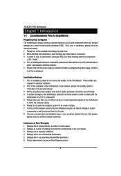
... harm to the user. 8. Damage due to use of an antistatic pad or within the computer casing. 6. Please make sure there are connected. 4. GA-6QPCV-RH Motherboard Chapter 1 Introduction 1-1 Considerations Prior to Installation Preparing Your Computer The motherboard contains numerous delicate electronic circuits and components which can lead to damage to...please do not allow screws to wear an electrostatic discharge (ESD) cuff when handling electronic components (CPU, RAM). 4. Damage due to be an unofficial Gigabyte product. 5 Product determined to improper installation. 4.
... harm to the user. 8. Damage due to use of an antistatic pad or within the computer casing. 6. Please make sure there are connected. 4. GA-6QPCV-RH Motherboard Chapter 1 Introduction 1-1 Considerations Prior to Installation Preparing Your Computer The motherboard contains numerous delicate electronic circuits and components which can lead to damage to...please do not allow screws to wear an electrostatic discharge (ESD) cuff when handling electronic components (CPU, RAM). 4. Damage due to be an unofficial Gigabyte product. 5 Product determined to improper installation. 4.
Manual
Page 6
... MEBx Set desired Intel® ME and Intel® AMT settings Restart the system and begin Intel® AMT & Intel® TPM testing Install OS 2. GA-6QPCV-RH 90W Adpater Max Support I. 2.5" HDD *4 II. 3.5" HDD * 2 6 Flash SPI ROM Update BIOS & ME need in accordance with the worksheet (Please see the illustrated table below...
... MEBx Set desired Intel® ME and Intel® AMT settings Restart the system and begin Intel® AMT & Intel® TPM testing Install OS 2. GA-6QPCV-RH 90W Adpater Max Support I. 2.5" HDD *4 II. 3.5" HDD * 2 6 Flash SPI ROM Update BIOS & ME need in accordance with the worksheet (Please see the illustrated table below...
Manual
Page 7
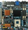
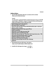
GA-6QPCV-RH Motherboard 4. Suggested to blow the wind generated by system fan to the DC convertor near CPU. (Please see the marked location below:) 7
GA-6QPCV-RH Motherboard 4. Suggested to blow the wind generated by system fan to the DC convertor near CPU. (Please see the marked location below:) 7
Manual
Page 8
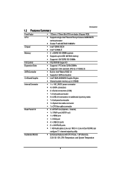
y Supports single Intel® Merom/Penryn/Celeron M585/M575 Chipset Memory I/O Control Expansion Slots SATA Controller On-Board Graphic Internal Connector Rear Panel I/O series processor y Socket P with 667/800/1066MHz y Intel® GM45 MCH y Intel® ICH9M-E y 2 x DDR2 SO-DIMM sockets y Supports up to 4GB 667/800 memory y Supports 1.8V DDR2 SO-DIMMs y ITE IT8718F Super I/O y Supports 1 PCI slots 32-Bit/33MHz y Supports 1 mini card slot (PCI-E x1/ USB 2.0) y Built in Intel® Matrix RAID 0,1 y Supports 4 SATA connectors y Intel® GMA 4500MHD Graphic Engine y Shared system memory ...
y Supports single Intel® Merom/Penryn/Celeron M585/M575 Chipset Memory I/O Control Expansion Slots SATA Controller On-Board Graphic Internal Connector Rear Panel I/O series processor y Socket P with 667/800/1066MHz y Intel® GM45 MCH y Intel® ICH9M-E y 2 x DDR2 SO-DIMM sockets y Supports up to 4GB 667/800 memory y Supports 1.8V DDR2 SO-DIMMs y ITE IT8718F Super I/O y Supports 1 PCI slots 32-Bit/33MHz y Supports 1 mini card slot (PCI-E x1/ USB 2.0) y Built in Intel® Matrix RAID 0,1 y Supports 4 SATA connectors y Intel® GMA 4500MHD Graphic Engine y Shared system memory ...
Manual
Page 9
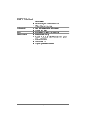
GA-6QPCV-RH Motherboard y y On-Board LAN y y BIOS y Additional Features y y y y y values viewing CPU/Power/System Fan Revolution Detect CPU shutdown when overheat Intel® 82567LM and 82574L GbE controllers Supports WOL, PXE Phoenix BIOS on 16Mb x 2 SPI Flash ROM External Modem wake up Supports S1, S3, S4, S5 under Windows Operating System Wake on LAN (WOL) Supports IAMT 4.0 Supports 3-pin system fan controller 9
GA-6QPCV-RH Motherboard y y On-Board LAN y y BIOS y Additional Features y y y y y values viewing CPU/Power/System Fan Revolution Detect CPU shutdown when overheat Intel® 82567LM and 82574L GbE controllers Supports WOL, PXE Phoenix BIOS on 16Mb x 2 SPI Flash ROM External Modem wake up Supports S1, S3, S4, S5 under Windows Operating System Wake on LAN (WOL) Supports IAMT 4.0 Supports 3-pin system fan controller 9
Manual
Page 10
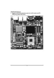
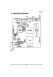
1.3 Motherboard Components PS/2 HDMI Introduction DC Power Jack Audio USB USB jack & & VGA LAN LAN F_Audio LVDS_CTL1 Intel Intel 82567LM 82574L SPDIF YPbPr Intel ICH9M-E Intel GM45 DDR 1 DDR 2 LVDS (Master) LVDS (Slave) PCI 32/33MHz SYS_FAN COM1 COM2 Mini PCI-E ITE IT8718F SATA3 SATA2 F_USB1 SATA4 SATA1 F_USB2 F_USB3 F_Panel PWR1 PWR2 Battery CPU CPU_FAN 10
1.3 Motherboard Components PS/2 HDMI Introduction DC Power Jack Audio USB USB jack & & VGA LAN LAN F_Audio LVDS_CTL1 Intel Intel 82567LM 82574L SPDIF YPbPr Intel ICH9M-E Intel GM45 DDR 1 DDR 2 LVDS (Master) LVDS (Slave) PCI 32/33MHz SYS_FAN COM1 COM2 Mini PCI-E ITE IT8718F SATA3 SATA2 F_USB1 SATA4 SATA1 F_USB2 F_USB3 F_Panel PWR1 PWR2 Battery CPU CPU_FAN 10
Manual
Page 11
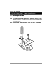
Refer to secure the processor. Insert the CPU into the socket, lock the screw. GA-6QPCV-RH Motherboard Chapter 2 Hardware Installation Process 2-1: Installing Processor Step 1 Step 2 The processor socket come with the notch on the inside of the CPUcorresponds with a screw to the figures below. 1 2 Lock Unlock 11 Once the processor has slide into the socket by making sure the notch on the corner of the socket.
Refer to secure the processor. Insert the CPU into the socket, lock the screw. GA-6QPCV-RH Motherboard Chapter 2 Hardware Installation Process 2-1: Installing Processor Step 1 Step 2 The processor socket come with the notch on the inside of the CPUcorresponds with a screw to the figures below. 1 2 Lock Unlock 11 Once the processor has slide into the socket by making sure the notch on the corner of the socket.
Manual
Page 12
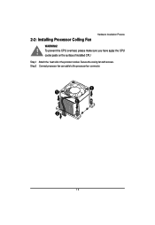
Secure the cooing fan with screws. Step 2 Connect processor fan can cable to the processor fan connector. 1 1 1 2 12 2-2: Installing Processor Colling Fan Hardware Installation Process WARNING! ! To prevent the CPU overheat, please make sure you have apply the CPU cooler paste on the surface of installed CPU Step 1 Attach the heat sink n the procssor socket.
Secure the cooing fan with screws. Step 2 Connect processor fan can cable to the processor fan connector. 1 1 1 2 12 2-2: Installing Processor Colling Fan Hardware Installation Process WARNING! ! To prevent the CPU overheat, please make sure you have apply the CPU cooler paste on the surface of installed CPU Step 1 Attach the heat sink n the procssor socket.
Manual
Page 13
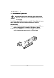
...-DIMM exactly match the notch in place. Step 2. Reverse the installation steps if you want to remove the SO-DIMM module. 13 Installation Steps: Step 1. GA-6QPCV-RH Motherboard 2-3: Install Memory Modules Before installing the memory modules, please comply with the following conditions: 1. The memory module only can be inserted in one direction.
...-DIMM exactly match the notch in place. Step 2. Reverse the installation steps if you want to remove the SO-DIMM module. 13 Installation Steps: Step 1. GA-6QPCV-RH Motherboard 2-3: Install Memory Modules Before installing the memory modules, please comply with the following conditions: 1. The memory module only can be inserted in one direction.
Manual
Page 14
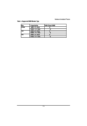
Table 1. Supported DIMM Module Type Size 512MB 1GB 2GB Organization 16MB x 8 x 8bks 32MB x 16 x 8bks 32MB x 8 x 8bks 64MB x 16 x 8bks 32MB x 8 x 8bks 64MB x 16 x 8bks Hardware Installation Process RAM Chips/DIMM 8 16 8 16 8 16 14
Table 1. Supported DIMM Module Type Size 512MB 1GB 2GB Organization 16MB x 8 x 8bks 32MB x 16 x 8bks 32MB x 8 x 8bks 64MB x 16 x 8bks 32MB x 8 x 8bks 64MB x 16 x 8bks Hardware Installation Process RAM Chips/DIMM 8 16 8 16 8 16 14
Manual
Page 15
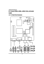
GA-6QPCV-RH Motherboard 2-4: Connect ribbon cables, cabinet wires, and power supply 2-4-1 : I/O Back Panel Introduction 15
GA-6QPCV-RH Motherboard 2-4: Connect ribbon cables, cabinet wires, and power supply 2-4-1 : I/O Back Panel Introduction 15
Manual
Page 16
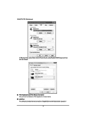
NOTE: After installing the HDMI device, make sure the default device for decoding.) In Windows XP, select Start>Control Panel>Sounds and Audio Devices>Audio, set Onboard VGA output connect to this port. VGA Port Connect the monitor cable to D-SUB/ HDMI under Advanced BIOS Features. Please note the HDMI audio output only supports AC3, DTS and 2-channel-LPCM formats. (AC3 and DTS require the use of an external decoder for sound playback is HDCP compliant. Connect the YPbPr cable to this port. The HDMI Technology can support a maximum resolution of three inputs or outputs on ...
NOTE: After installing the HDMI device, make sure the default device for decoding.) In Windows XP, select Start>Control Panel>Sounds and Audio Devices>Audio, set Onboard VGA output connect to this port. VGA Port Connect the monitor cable to D-SUB/ HDMI under Advanced BIOS Features. Please note the HDMI audio output only supports AC3, DTS and 2-channel-LPCM formats. (AC3 and DTS require the use of an external decoder for sound playback is HDCP compliant. Connect the YPbPr cable to this port. The HDMI Technology can support a maximum resolution of three inputs or outputs on ...
Manual
Page 17
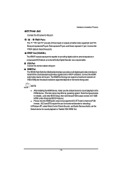
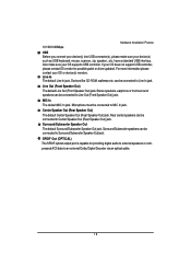
LAN Port The LAN port provides Internet connection of Gigabit Ethernet with data transfer speeds of 17 PS/2 Keyboard and PS/2 Mouse Connector This port can be installed a PS/2 keyboard or mouse device. GA-6QPCV-RH Motherboard In Windows Vista, select Start>Control Panel>Sound, select Realtek HDMI Output and then click Set Default.
LAN Port The LAN port provides Internet connection of Gigabit Ethernet with data transfer speeds of 17 PS/2 Keyboard and PS/2 Mouse Connector This port can be installed a PS/2 keyboard or mouse device. GA-6QPCV-RH Motherboard In Windows Vista, select Start>Control Panel>Sound, select Realtek HDMI Output and then click Set Default.
Manual
Page 18
Also make sure your OS does not support USB controller, please contact OS vendor for providing digital audio to external speakers or compressed AC3 data to MIC In jack. Line Out (Front Speaker Out) The default Line Out (Front Speaker Out) jack. Surround/Subwoofer Speaker Out The default Surround/Subwoofer Speaker Out jack. For more information please contact your OS supports USB controller. have a standard USB interface. MIC In The default MIC In jack. SPDIF Out (OPTICAL) The SPDIF optical output port is capable for possible patch or driver updated. Microphone must...
Also make sure your OS does not support USB controller, please contact OS vendor for providing digital audio to external speakers or compressed AC3 data to MIC In jack. Line Out (Front Speaker Out) The default Line Out (Front Speaker Out) jack. Surround/Subwoofer Speaker Out The default Surround/Subwoofer Speaker Out jack. For more information please contact your OS supports USB controller. have a standard USB interface. MIC In The default MIC In jack. SPDIF Out (OPTICAL) The SPDIF optical output port is capable for possible patch or driver updated. Microphone must...
Manual
Page 19
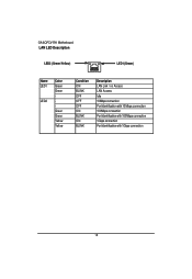
GA-6QPCV-RH Motherboard LAN LED Description LED2 (Green/Yellow) LED1 (Green) Name LED1 LED2 Color Green Green Green Green Yellow Yellow Condition ON BLINK OFF OFF OFF ON BLINK ON BLINK Description LAN Link / no Access LAN Access Idle 10Mbps connection Port identification with 10 Mbps connection 100Mbps connection Port identification with 100Mbps connection 1Gbps connection Port identification with 1Gbps connection 19
GA-6QPCV-RH Motherboard LAN LED Description LED2 (Green/Yellow) LED1 (Green) Name LED1 LED2 Color Green Green Green Green Yellow Yellow Condition ON BLINK OFF OFF OFF ON BLINK ON BLINK Description LAN Link / no Access LAN Access Idle 10Mbps connection Port identification with 10 Mbps connection 100Mbps connection Port identification with 100Mbps connection 1Gbps connection Port identification with 1Gbps connection 19
Manual
Page 20
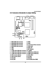
F_USB2 (Fornt USB cable connector) 21. LVDS connector (Master) 23. LVDS_PSEL2 11. CPU_FAN1 25. SATA1 (SATA cable connector) 14. PWR1 2. PWR2 3. F_USB1 (Fornt USB cable connector) 20. F_AUDIO1 8. COMS1 (Power COM select) 10. CLR_ME1 12. CLR_CMOS (Clear CMOS) 20 Connector Introduction 2-5: Connectors Introduction & Jumper Setting 20 23 18 24 25 5 21 6 22 10 11 26 13 14 3 74 2 1 15 89 12 16 17 19 1. WLAN_LED1 5. BAT1 (Battery) 7. LVDS connector (Slave) 24. SATA3 (SATA cable connector) 16. COM2 19. F_USB3 (Fornt USB cable connector) 22. F_Panel (...
F_USB2 (Fornt USB cable connector) 21. LVDS connector (Master) 23. LVDS_PSEL2 11. CPU_FAN1 25. SATA1 (SATA cable connector) 14. PWR1 2. PWR2 3. F_USB1 (Fornt USB cable connector) 20. F_AUDIO1 8. COMS1 (Power COM select) 10. CLR_ME1 12. CLR_CMOS (Clear CMOS) 20 Connector Introduction 2-5: Connectors Introduction & Jumper Setting 20 23 18 24 25 5 21 6 22 10 11 26 13 14 3 74 2 1 15 89 12 16 17 19 1. WLAN_LED1 5. BAT1 (Battery) 7. LVDS connector (Slave) 24. SATA3 (SATA cable connector) 16. COM2 19. F_USB3 (Fornt USB cable connector) 22. F_Panel (...
