Manual
Page 3
...Memory 17 1-4-1 Dual Channel Memory Configuration 17 1-4-2 Installing a Memory 18 1-5 Back Panel Connectors 19 1-6 Internal Connectors 21 Chapter 2 BIOS Setup 36 2-1 The Main Menu 38 2-2 Advanced Menu 40 2-2-1 ACPI Configuration 41 2-2-2 Trusted Computing (Optional 42 2-2-3 PCI Subsystem Settings 43 2-2-3-1 PCI Express Settings 45 2-2-4 CPU Configuration 47 2-2-5 SATA Configuration 51 2-2-5-1 Software Feature Mask Configuration 53 2-2-6 Info Report Configuration 55 2-2-7 USB Configuration 56 2-2-8 IT8732 Super IO Configuration 57 2-2-9 IT8732 HW Monitor 59 2-2-10 Serial Port...
...Memory 17 1-4-1 Dual Channel Memory Configuration 17 1-4-2 Installing a Memory 18 1-5 Back Panel Connectors 19 1-6 Internal Connectors 21 Chapter 2 BIOS Setup 36 2-1 The Main Menu 38 2-2 Advanced Menu 40 2-2-1 ACPI Configuration 41 2-2-2 Trusted Computing (Optional 42 2-2-3 PCI Subsystem Settings 43 2-2-3-1 PCI Express Settings 45 2-2-4 CPU Configuration 47 2-2-5 SATA Configuration 51 2-2-5-1 Software Feature Mask Configuration 53 2-2-6 Info Report Configuration 55 2-2-7 USB Configuration 56 2-2-8 IT8732 Super IO Configuration 57 2-2-9 IT8732 HW Monitor 59 2-2-10 Serial Port...
Manual
Page 7
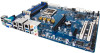
...channel 1 slot 1 ) DIMM slot (channel 2 slot 0 ) DIMM slot (channel 2 slot 1 ) Intel LGA1150 socket 24 pin main power connector System fan connector#4 System fan connector#3 Case open intrusion header BIOS recovery jumper Clear CMOS jumper ME recovery jumper Clearing supervisor password jumper TPM module connector SATA 6Gb/s connectors SATA 6Gb/s connectors SATA 6Gb/s connector SATA 6Gb/s connector SATA port 1 DOM support jumper SATA port 0 DOM support jumper System fan connector#2 System fan connector#1 USB 3.0 header USB 2.0 Type A connector USB 2.0 header Intel H87 Express chipset ME Update...
...channel 1 slot 1 ) DIMM slot (channel 2 slot 0 ) DIMM slot (channel 2 slot 1 ) Intel LGA1150 socket 24 pin main power connector System fan connector#4 System fan connector#3 Case open intrusion header BIOS recovery jumper Clear CMOS jumper ME recovery jumper Clearing supervisor password jumper TPM module connector SATA 6Gb/s connectors SATA 6Gb/s connectors SATA 6Gb/s connector SATA 6Gb/s connector SATA port 1 DOM support jumper SATA port 0 DOM support jumper System fan connector#2 System fan connector#1 USB 3.0 header USB 2.0 Type A connector USB 2.0 header Intel H87 Express chipset ME Update...

Manual
Page 8
... cable connector SPDIF In header (Upper) SPDIF Out header (Bottom) Front audio header PCI 32bit/33MHz slot PCI 32bit/33MHz slot PCI-E x1 slot Battery socket PCI-E x16 slot Intel I210 GbE LAN chipset (GA-6LXSG) Realtek RTL8111F GbE LAN chipset (GA-6LXSL) Intel I210 GbE LAN chipset (GA-6LXSG) Realtek RTL8111F GbE LAN chipset (GA-6LXSL) Intel I210 GbE LAN chipset (GA-6LXSG) Realtek RTL8111F GbE LAN chipset (GA-6LXSL) Intel I210 GbE LAN chipset (GA-6LXSG) Realtek RTL8111F GbE LAN chipset (GA-6LXSL) CAUTION! If a SATA type hard drive is connected to the motherboard, please ensure the jumper...
... cable connector SPDIF In header (Upper) SPDIF Out header (Bottom) Front audio header PCI 32bit/33MHz slot PCI 32bit/33MHz slot PCI-E x1 slot Battery socket PCI-E x16 slot Intel I210 GbE LAN chipset (GA-6LXSG) Realtek RTL8111F GbE LAN chipset (GA-6LXSL) Intel I210 GbE LAN chipset (GA-6LXSG) Realtek RTL8111F GbE LAN chipset (GA-6LXSL) Intel I210 GbE LAN chipset (GA-6LXSG) Realtek RTL8111F GbE LAN chipset (GA-6LXSL) Intel I210 GbE LAN chipset (GA-6LXSG) Realtek RTL8111F GbE LAN chipset (GA-6LXSL) CAUTION! If a SATA type hard drive is connected to the motherboard, please ensure the jumper...

Manual
Page 11
... not allow screws to come in a high-temperature environment. • Turning on the motherboard, make sure the power supply voltage has been set according to the local voltage standard. • Before using the product, please verify that all cables and power connectors of the product, please consult a certified computer technician. - 11 - Hardware Installation Prior to installation, carefully read the user's manual and follow these procedures: • Prior...
... not allow screws to come in a high-temperature environment. • Turning on the motherboard, make sure the power supply voltage has been set according to the local voltage standard. • Before using the product, please verify that all cables and power connectors of the product, please consult a certified computer technician. - 11 - Hardware Installation Prior to installation, carefully read the user's manual and follow these procedures: • Prior...

Manual
Page 12
... chipset supports for RAID 0/1/10 Up to 7 USB 2.0 ports (4 on the back panel, 1 Type A connector, 2 via the USB brackets connected to the internal USB headers) Up to 4 USB 3.0 ports (2 on the back panel, 2 via the USB brackets connected to the internal USB headers) 1 x PCIe x16 slot (Gen3 x16 bus) 1 x PCIe x1 slot (Gen2 x1 bus) 2 x PCI 32bit/33MHz slots 1 x 24-pin ATX main power connector 1 x 8-pin ATX 12V power connector 10 x SATA 6Gb/s connectors 1 x CPU fan header 4 x System fan header 1 x Front panel header 1 x PMBus header 1 x Front USB 3.0 header 1 x Front USB 2.0 header 1 x USB 2.0 Type...
... chipset supports for RAID 0/1/10 Up to 7 USB 2.0 ports (4 on the back panel, 1 Type A connector, 2 via the USB brackets connected to the internal USB headers) Up to 4 USB 3.0 ports (2 on the back panel, 2 via the USB brackets connected to the internal USB headers) 1 x PCIe x16 slot (Gen3 x16 bus) 1 x PCIe x1 slot (Gen2 x1 bus) 2 x PCI 32bit/33MHz slots 1 x 24-pin ATX main power connector 1 x 8-pin ATX 12V power connector 10 x SATA 6Gb/s connectors 1 x CPU fan header 4 x System fan header 1 x Front panel header 1 x PMBus header 1 x Front USB 3.0 header 1 x Front USB 2.0 header 1 x USB 2.0 Type...

Manual
Page 17
... to insert the memory, switch the direction. 1-4-1 Dual Channel Memory Configuration This motherboard provides four DDR3 memory sockets and supports Dual Channel Technology. Dual Channel mode cannot be used . • Always turn off the computer and unplug the power cord from the power outlet before installing the memory to CPU limitations, read the following guidelines before you are divided into two channels and each channel has two memory sockets as following guidelines before installing the memory in only one...
... to insert the memory, switch the direction. 1-4-1 Dual Channel Memory Configuration This motherboard provides four DDR3 memory sockets and supports Dual Channel Technology. Dual Channel mode cannot be used . • Always turn off the computer and unplug the power cord from the power outlet before installing the memory to CPU limitations, read the following guidelines before you are divided into two channels and each channel has two memory sockets as following guidelines before installing the memory in only one...

Manual
Page 19
... keyboard/mouse, USB printer, USB flash drive and etc. RJ-45 LAN Port The Gigabit Ethernet LAN port provides Internet connection at up to serial-based mouse or data processing devices. Side Speaker Out Jack (Gray) Use this audio jack to connect side speakers in a 7.1-channel audio configuration. Hardware Installation Rear Speaker Out Jack (Black) Use this audio jack to connect rear speakers in a 4/5.1/7.1-channel audio configuration. Microphones must be used to connect front speakers in , which can be connected to video in a 4/5.1/7.1-channel audio configuration. VGA...
... keyboard/mouse, USB printer, USB flash drive and etc. RJ-45 LAN Port The Gigabit Ethernet LAN port provides Internet connection at up to serial-based mouse or data processing devices. Side Speaker Out Jack (Gray) Use this audio jack to connect side speakers in a 7.1-channel audio configuration. Hardware Installation Rear Speaker Out Jack (Black) Use this audio jack to connect rear speakers in a 4/5.1/7.1-channel audio configuration. Microphones must be used to connect front speakers in , which can be connected to video in a 4/5.1/7.1-channel audio configuration. VGA...

Manual
Page 24
... a system fan be sure to connect it in damage to prevent your CPU and system from overheating. Most fan headers possess a foolproof insertion design. The motherboard supports CPU fan speed control, which requires the use of a CPU fan with fan speed control design. 3/4/5/6/7) CPU0_FAN/SYS_FAN1/SYS_FAN2/SYS_FAN3/SYS_FAN4 (CPU Fan/System Fan Headers) The motherboard has a 4-pin CPU fan header (CPU0_FAN), and four 4-pin (SYS_FAN1/SYS_FAN2/ SYS_FAN3/SYS_FAN4) system fan headers. Overheating may hang. • These fan headers are not configuration jumper blocks.
... a system fan be sure to connect it in damage to prevent your CPU and system from overheating. Most fan headers possess a foolproof insertion design. The motherboard supports CPU fan speed control, which requires the use of a CPU fan with fan speed control design. 3/4/5/6/7) CPU0_FAN/SYS_FAN1/SYS_FAN2/SYS_FAN3/SYS_FAN4 (CPU Fan/System Fan Headers) The motherboard has a 4-pin CPU fan header (CPU0_FAN), and four 4-pin (SYS_FAN1/SYS_FAN2/ SYS_FAN3/SYS_FAN4) system fan headers. Overheating may hang. • These fan headers are not configuration jumper blocks.

Manual
Page 36
...'t flash the BIOS. To access the BIOS Setup program, press the key during system startup, saving system parameters and loading operating system, etc. Inadequately altering the settings may result in system's failure to keep the configuration values in the EFI on the motherboard. BIOS includes a BIOS Setup program that you not alter the default settings (unless you do it is turned off, the battery on the motherboard supplies the necessary power...
...'t flash the BIOS. To access the BIOS Setup program, press the key during system startup, saving system parameters and loading operating system, etc. Inadequately altering the settings may result in system's failure to keep the configuration values in the EFI on the motherboard. BIOS includes a BIOS Setup program that you not alter the default settings (unless you do it is turned off, the battery on the motherboard supplies the necessary power...
Manual
Page 43
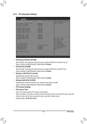
... Register. Options available: Enabled/Disabled. Onboard LAN #1/2/3/4 Controller Enable/Disable Onboard LAN controllers. Options available: 32 PCI Bus Clocks/64 PCI Bus Clocks/96 PCI Bus Clocks/128 PCI Bus Clocks/160 PCI Bus Clocks/192 PCI Bus Clocks/224 PCI Bus Clocks/248 PCI Bus Clocks/. Default setting is Enabled. Options available: Enabled/Disabled. Options available: Enabled/Disabled. Options available: Enabled/Disabled. Onboard LAN1/2/3/4 I/O ROM Enable/Disable onboard LAN devices and initialize device expansion ROM. PCI Slot #1/2 I/O ROM When enabled, This setting will...
... Register. Options available: Enabled/Disabled. Onboard LAN #1/2/3/4 Controller Enable/Disable Onboard LAN controllers. Options available: 32 PCI Bus Clocks/64 PCI Bus Clocks/96 PCI Bus Clocks/128 PCI Bus Clocks/160 PCI Bus Clocks/192 PCI Bus Clocks/224 PCI Bus Clocks/248 PCI Bus Clocks/. Default setting is Enabled. Options available: Enabled/Disabled. Options available: Enabled/Disabled. Options available: Enabled/Disabled. Onboard LAN1/2/3/4 I/O ROM Enable/Disable onboard LAN devices and initialize device expansion ROM. PCI Slot #1/2 I/O ROM When enabled, This setting will...
Manual
Page 45
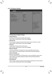
... Disabled. Options available: Enabled/Disabled. Default setting is enabled, the system will allow generation of Extended Synchronization patterns. Options available: Auto/128 Bytes/256 Bytes/512 Bytes/1024 Bytes/2048 Bytes/4096 Bytes. Extended Synch Wnen this feature is Auto. BIOS Setup No Snoop Enable/Disable PCI Express Device No Snoop option. Maximum Read Request Set maximum Read Reuest size for PCI Express Device or allow system BIOS to use 8-bit Tag field as a requester. 2-2-3-1 PCI Express Settings PCI Express Device Register Settings...
... Disabled. Options available: Enabled/Disabled. Default setting is enabled, the system will allow generation of Extended Synchronization patterns. Options available: Auto/128 Bytes/256 Bytes/512 Bytes/1024 Bytes/2048 Bytes/4096 Bytes. Extended Synch Wnen this feature is Auto. BIOS Setup No Snoop Enable/Disable PCI Express Device No Snoop option. Maximum Read Request Set maximum Read Reuest size for PCI Express Device or allow system BIOS to use 8-bit Tag field as a requester. 2-2-3-1 PCI Express Settings PCI Express Device Register Settings...

Manual
Page 48
... memory pages. Options available: Enabled/Disabled. CPU Configuration CPU Type/Signature/Processor Family/Microcode Patch/FSB Speed/Max CPU Speed/ Min CPU Speed/Processor Cores/Intel HT Technology/Intel VT-x Technology/ Intel SMX Technology Displays the technical specifications for the installed processor. Cache Information L1 Data Cache / L1 Code Cache / L2 Cache / L3 Cache Displays the technical specifications for the installed processor. 64-bit Display the supported information of code in any memory area. Default setting is Disabled. Overclocking lock Enable/Disable Overclocking...
... memory pages. Options available: Enabled/Disabled. CPU Configuration CPU Type/Signature/Processor Family/Microcode Patch/FSB Speed/Max CPU Speed/ Min CPU Speed/Processor Cores/Intel HT Technology/Intel VT-x Technology/ Intel SMX Technology Displays the technical specifications for the installed processor. Cache Information L1 Data Cache / L1 Code Cache / L2 Cache / L3 Cache Displays the technical specifications for the installed processor. 64-bit Display the supported information of code in any memory area. Default setting is Disabled. Overclocking lock Enable/Disable Overclocking...

Manual
Page 49
.... Turbo Mode When this item is disabled, the processor will automatically ramp up the clock speed of 1-2 of the processor. Energy Performance Energy Performance Bias is present only if you install a CPU that supports this item is enabled, tje processor will not overclock any of its performance. Platform power limit lock Options available: Enabled/Disabled. CPU AES Enable/Disable CPU Advanced Encryption Standard instructions. Boot performance mode Configure the Boot performance mode. Default setting is Performance. Options available: Performance...
.... Turbo Mode When this item is disabled, the processor will automatically ramp up the clock speed of 1-2 of the processor. Energy Performance Energy Performance Bias is present only if you install a CPU that supports this item is enabled, tje processor will not overclock any of its performance. Platform power limit lock Options available: Enabled/Disabled. CPU AES Enable/Disable CPU Advanced Encryption Standard instructions. Boot performance mode Configure the Boot performance mode. Default setting is Performance. Options available: Performance...

Manual
Page 50
... the CPU enter C3/C6 mode in system halt state. Default setting is Enabled. Options available: Enabled/Disabled. Default setting is Disabled. Options available: Enabled/Disabled. Package C state demotion Configure state for the C-State package limit. Default setting is a more enhanced power-saving state than C1. Options available: Enabled/Disabled. ACPI T State Enable/Disable ACPI T state support. CPU DTS Enable/Disable CPU DTS support. The C3/C6 state is Enabled. Default setting is Disabled. Options available: Enabled/Disabled. Default setting is Enabled. Default...
... the CPU enter C3/C6 mode in system halt state. Default setting is Enabled. Options available: Enabled/Disabled. Default setting is Disabled. Options available: Enabled/Disabled. Package C state demotion Configure state for the C-State package limit. Default setting is a more enhanced power-saving state than C1. Options available: Enabled/Disabled. ACPI T State Enable/Disable ACPI T state support. CPU DTS Enable/Disable CPU DTS support. The C3/C6 state is Enabled. Default setting is Disabled. Options available: Enabled/Disabled. Default setting is Enabled. Default...

Manual
Page 52
.... BIOS Setup - 52 - Default setting is Disabled. RAID Mode: When set to RAID, the SATA controllerenables both its RAID and AHCI functions and runs in the computer. ACHI Mode: When set to AHCI,the SATA controller enables its AHCI functionality. Default setting is Enabled. Default setting is Default. You will automatically detect HDD type. Default setting is Disabled. Default setting is not allowed to IDE, the SATA controller disables its RAID and AHCI functions. System will be access the RAID setup utility at boot time. Hot Plug (for Serial SATA Port...
.... BIOS Setup - 52 - Default setting is Disabled. RAID Mode: When set to RAID, the SATA controllerenables both its RAID and AHCI functions and runs in the computer. ACHI Mode: When set to AHCI,the SATA controller enables its AHCI functionality. Default setting is Enabled. Default setting is Default. You will automatically detect HDD type. Default setting is Disabled. Default setting is not allowed to IDE, the SATA controller disables its RAID and AHCI functions. System will be access the RAID setup utility at boot time. Hot Plug (for Serial SATA Port...
Manual
Page 56
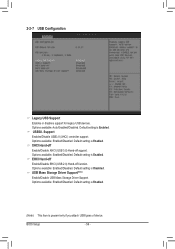
... setting is present only if you attach USB types of device. Options available: Enabled/Disabled. Default setting is Enabled. (Note) This item is Enabled. Options available: Enabled/Disabled. Options available: Enabled/Disabled. EHCI Hand-off Enable/Disable EHCI (USB 2.0) Hand-off support. Default setting is Disabled. USB30. XHCI Hand-off Enable/Disable XHCI (USB 3.0) Hand-off function. 2-2-7 USB Configuration Legacy USB Support Enables or disables support for legacy USB devices. USB Mass Storage Driver Support(Note) Enable/Disable USB Mass Storage Driver Support. BIOS Setup...
... setting is present only if you attach USB types of device. Options available: Enabled/Disabled. Default setting is Enabled. (Note) This item is Enabled. Options available: Enabled/Disabled. Options available: Enabled/Disabled. EHCI Hand-off Enable/Disable EHCI (USB 2.0) Hand-off support. Default setting is Disabled. USB30. XHCI Hand-off Enable/Disable XHCI (USB 3.0) Hand-off function. 2-2-7 USB Configuration Legacy USB Support Enables or disables support for legacy USB devices. USB Mass Storage Driver Support(Note) Enable/Disable USB Mass Storage Driver Support. BIOS Setup...

Manual
Page 62
... mode enabled, only text will be sent to send start bit indicates the beginning). Hardware flow control uses two wires to re-start ' signal can be send. Options available: Enabled/Disabled. Redirection After BIOS POST (Note) This option allows user to capture Terminal data. Default setting is to enable console redirection after O.S has loaded. Options available: Enabled/Disabled. Legacy OS Redirection Resolution (Note) On Legacy OS, the number of a Windows Server OS through a serial port. This is Enabled. Default setting...
... mode enabled, only text will be sent to send start bit indicates the beginning). Hardware flow control uses two wires to re-start ' signal can be send. Options available: Enabled/Disabled. Redirection After BIOS POST (Note) This option allows user to capture Terminal data. Default setting is to enable console redirection after O.S has loaded. Options available: Enabled/Disabled. Legacy OS Redirection Resolution (Note) On Legacy OS, the number of a Windows Server OS through a serial port. This is Enabled. Default setting...
Manual
Page 68
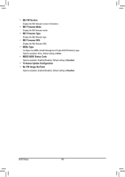
ME Firmware Type Display the ME firmware type. ME Firmware SKU Display the ME firmware SKU. MEBx Type Configure the MEBx (Intel® Management Engine BIOS Extention) type . MEDS BIOS Status Code Options available: Enabled/DIsabled. BIOS Setup - 68 - ME FW Version Display the ME firmware version information. Default setting is None. Options available: None. Default setting is Disabled. Firmware Update Configuration Me FW Image Re-Flash Options available: Enabled/DIsabled. Default setting is Disabled. ME Firmware Mode Display the ME firmware mode.
ME Firmware Type Display the ME firmware type. ME Firmware SKU Display the ME firmware SKU. MEBx Type Configure the MEBx (Intel® Management Engine BIOS Extention) type . MEDS BIOS Status Code Options available: Enabled/DIsabled. BIOS Setup - 68 - ME FW Version Display the ME firmware version information. Default setting is None. Options available: None. Default setting is Disabled. Firmware Update Configuration Me FW Image Re-Flash Options available: Enabled/DIsabled. Default setting is Disabled. ME Firmware Mode Display the ME firmware mode.

Manual
Page 75
...Audio Device (B0:D3:F0) Enable/Disable CPU SA audio device. System Agent RC Version Display the version number of advanced items. - 75 - Default setting is Enabled. BIOS Setup Default setting is Enabled. Options available: Enabled/DIsabled. Graphics Configuration Press [Enter] for configuration of advanced items. NB PCIe Configuration Press [Enter] for configuration of advanced items. Memory Configuration Press [Enter] for Directed I/O (VT-d) feature. Enable NB CRID Options available: Enabled/DIsabled. VT-d Enable/Disable Intel Virtualization Technology for configuration...
...Audio Device (B0:D3:F0) Enable/Disable CPU SA audio device. System Agent RC Version Display the version number of advanced items. - 75 - Default setting is Enabled. BIOS Setup Default setting is Enabled. Options available: Enabled/DIsabled. Graphics Configuration Press [Enter] for configuration of advanced items. NB PCIe Configuration Press [Enter] for configuration of advanced items. Memory Configuration Press [Enter] for Directed I/O (VT-d) feature. Enable NB CRID Options available: Enabled/DIsabled. VT-d Enable/Disable Intel Virtualization Technology for configuration...

Manual
Page 79
...available: Enabled/Disabled. Default setting is Disabled. Options available: Options available: -6 dB/-3.5 dB. Default setting is -3.5 dB. Default setting is Disabled. Options available: Enabled/Disabled. PEG1 - PEG2 - Options available: Reduced/Half/Full. PEG1 De-emphasis Control PEG1:Configure the De-emphasis control on PEG. Options available: Enabled/Disabled. Default setting is Enabled. Options available: Enabled/Disabled. ASPM Control ASPM support for IVB A0 B0. Default setting is Full. Detect Non-Compliance Device Detect Non-Compliance PCI Express Device in...
...available: Enabled/Disabled. Default setting is Disabled. Options available: Options available: -6 dB/-3.5 dB. Default setting is -3.5 dB. Default setting is Disabled. Options available: Enabled/Disabled. PEG1 - PEG2 - Options available: Reduced/Half/Full. PEG1 De-emphasis Control PEG1:Configure the De-emphasis control on PEG. Options available: Enabled/Disabled. Default setting is Enabled. Options available: Enabled/Disabled. ASPM Control ASPM support for IVB A0 B0. Default setting is Full. Detect Non-Compliance Device Detect Non-Compliance PCI Express Device in...


