Manual
Page 3
Table of Contents Box Contents...5 GA-6LXSG/GA-6LXSL Motherboard Layout 6 GA-6LXSG Block Diagram 9 GA-6LXSL Block Diagram 10 Chapter 1 Hardware Installation 11 1-1 Installation Precautions 11 1-2 Product Specifications 12 1-3 Installing the CPU ...17 1-4-1 Dual Channel Memory Configuration 17 1-4-2 Installing a Memory 18 1-5 Back Panel Connectors 19 1-6 Internal Connectors 21 Chapter 2 BIOS Setup 36 2-1 The Main Menu 38 2-2 Advanced Menu 40 2-2-1 ACPI Configuration 41 2-2-2 Trusted Computing (Optional 42 2-2-3 PCI Subsystem Settings 43 2-2-3-1 PCI Express Settings 45 2-2-4 CPU ...
Table of Contents Box Contents...5 GA-6LXSG/GA-6LXSL Motherboard Layout 6 GA-6LXSG Block Diagram 9 GA-6LXSL Block Diagram 10 Chapter 1 Hardware Installation 11 1-1 Installation Precautions 11 1-2 Product Specifications 12 1-3 Installing the CPU ...17 1-4-1 Dual Channel Memory Configuration 17 1-4-2 Installing a Memory 18 1-5 Back Panel Connectors 19 1-6 Internal Connectors 21 Chapter 2 BIOS Setup 36 2-1 The Main Menu 38 2-2 Advanced Menu 40 2-2-1 ACPI Configuration 41 2-2-2 Trusted Computing (Optional 42 2-2-3 PCI Subsystem Settings 43 2-2-3-1 PCI Express Settings 45 2-2-4 CPU ...
Manual
Page 7
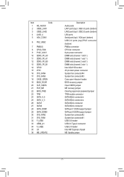
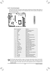
... connector 8 pin power connector DIMM slot (channel 1 slot 0 ) DIMM slot (channel 1 slot 1 ) DIMM slot (channel 2 slot 0 ) DIMM slot (channel 2 slot 1 ) Intel LGA1150 socket 24 pin main power connector System fan connector#4 System fan connector#3 Case open intrusion header BIOS recovery jumper Clear CMOS jumper ME recovery jumper Clearing supervisor password jumper...
... connector 8 pin power connector DIMM slot (channel 1 slot 0 ) DIMM slot (channel 1 slot 1 ) DIMM slot (channel 2 slot 0 ) DIMM slot (channel 2 slot 1 ) Intel LGA1150 socket 24 pin main power connector System fan connector#4 System fan connector#3 Case open intrusion header BIOS recovery jumper Clear CMOS jumper ME recovery jumper Clearing supervisor password jumper...

Manual
Page 12
...-ECC, un-buffered memory modules LAN ŠŠ 4 x Intel® I210 supports 10/100/1000 Mbps (GA-6LXSG) ŠŠ 4 x Realtek® 8111F-VB supports 10/100/1000 Mbps (GA-6LXSL) Onboard ŠŠ Build-In Intel® H87 Express chipset Graphics Onboard Audio ŠŠ Realtek®...to the internal USB headers) 1 x PCIe x16 slot (Gen3 x16 bus) 1 x PCIe x1 slot (Gen2 x1 bus) 2 x PCI 32bit/33MHz slots 1 x 24-pin ATX main power connector 1 x 8-pin ATX 12V power connector 10 x SATA 6Gb/s connectors 1 x CPU fan header 4 x System fan header 1 x Front panel header 1 x PMBus header 1...
...-ECC, un-buffered memory modules LAN ŠŠ 4 x Intel® I210 supports 10/100/1000 Mbps (GA-6LXSG) ŠŠ 4 x Realtek® 8111F-VB supports 10/100/1000 Mbps (GA-6LXSL) Onboard ŠŠ Build-In Intel® H87 Express chipset Graphics Onboard Audio ŠŠ Realtek®...to the internal USB headers) 1 x PCIe x16 slot (Gen3 x16 bus) 1 x PCIe x1 slot (Gen2 x1 bus) 2 x PCI 32bit/33MHz slots 1 x 24-pin ATX main power connector 1 x 8-pin ATX 12V power connector 10 x SATA 6Gb/s connectors 1 x CPU fan header 4 x System fan header 1 x Front panel header 1 x PMBus header 1...
Manual
Page 23
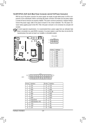
...that a power supply that does not provide the required power, the result can lead to all devices are properly installed. 1/2) ATX1/P12V_AUX1 (2x12 Main Power Connector and 2x4 12V Power Connector) With the use of the power connector, the power supply can withstand high power consumption be used (500W... or greater). The 12V power connector mainly supplies power to the power connector in the correct orientation. If the 12V power connector is turned off and all the components on the ...
...that a power supply that does not provide the required power, the result can lead to all devices are properly installed. 1/2) ATX1/P12V_AUX1 (2x12 Main Power Connector and 2x4 12V Power Connector) With the use of the power connector, the power supply can withstand high power consumption be used (500W... or greater). The 12V power connector mainly supplies power to the power connector in the correct orientation. If the 12V power connector is turned off and all the components on the ...
Manual
Page 26
... according to this header, make sure the wire assignments and the pin assignments are matched correctly. - 26 - NC L2_LINK NMI_SW- Hardware Installation A front panel module mainly consists of power switch, reset switch, power LED, hard drive activity LED, speaker and etc. Note the positive and negative pins before connecting the cables...
... according to this header, make sure the wire assignments and the pin assignments are matched correctly. - 26 - NC L2_LINK NMI_SW- Hardware Installation A front panel module mainly consists of power switch, reset switch, power LED, hard drive activity LED, speaker and etc. Note the positive and negative pins before connecting the cables...

Manual
Page 36
... bar to select an item Increase the numeric value or make changes Decrease the numeric value or make changes Execute command or enter the submenu Main Menu: Exit the BIOS Setup program Submenus: Exit current submenu Show descriptions of the battery/clearing CMOS jumper in system's failure to keep the configuration...
... bar to select an item Increase the numeric value or make changes Decrease the numeric value or make changes Execute command or enter the submenu Main Menu: Exit the BIOS Setup program Submenus: Exit current submenu Show descriptions of the battery/clearing CMOS jumper in system's failure to keep the configuration...
Manual
Page 37
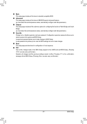
... parameters.) Security Change, set, or disable supervisor and user password. A user password only allows you to the system and BIOS Setup. BIOS Setup Main This setup page includes all the items in standard compatible BIOS. Advanced This setup page includes all the items of AMI BIOS special enhanced...
... parameters.) Security Change, set, or disable supervisor and user password. A user password only allows you to the system and BIOS Setup. BIOS Setup Main This setup page includes all the items in standard compatible BIOS. Advanced This setup page includes all the items of AMI BIOS special enhanced...

Manual
Page 38
... for each item is in the Item Help block on the right side of the submenu. • When the system is displayed on the screen. Main Menu Help The on-screen description of a highlighted setup option is not stable as shown below) appears on the bottom line of function keys available... menu. Use arrow keys to move among the items and press to exit the help screen (General Help) of the Main Menu. 2-1 The Main Menu Once you enter the BIOS Setup program, the Main Menu (as usual, select the Restore Defaults item to set your system to its defaults. • The BIOS Setup...
... for each item is in the Item Help block on the right side of the submenu. • When the system is displayed on the screen. Main Menu Help The on-screen description of a highlighted setup option is not stable as shown below) appears on the bottom line of function keys available... menu. Use arrow keys to move among the items and press to exit the help screen (General Help) of the Main Menu. 2-1 The Main Menu Once you enter the BIOS Setup program, the Main Menu (as usual, select the Restore Defaults item to set your system to its defaults. • The BIOS Setup...