Manual
Page 2
...GA-3CESL3-RH Motherboard Components 6 Chapter 2 Hardware Installation Process 8 2-1: Installing Processor and CPU Haet Sink 8 2-1-1: Installing CPU ...8 2-1-2: Installing Heat Sink 9 2-2: Install Memory Modules 10 2-3: Connect ribbon cables, cabinet wires, and power supply 13 2-3-1 : I/O Back Panel Introduction 13 2-4: Connectors Introduction 15 Chapter 3 BIOS Setup 27 Main ...29 Advanced 31 Advanced Processor Options 32 Memory Configuration ...35 Advanced Chipset Control 36 PCI Configuration ...38 I/O Device Configuration 40 IDE Configuration ...42 Floppy Configuration ...44 Boot...
...GA-3CESL3-RH Motherboard Components 6 Chapter 2 Hardware Installation Process 8 2-1: Installing Processor and CPU Haet Sink 8 2-1-1: Installing CPU ...8 2-1-2: Installing Heat Sink 9 2-2: Install Memory Modules 10 2-3: Connect ribbon cables, cabinet wires, and power supply 13 2-3-1 : I/O Back Panel Introduction 13 2-4: Connectors Introduction 15 Chapter 3 BIOS Setup 27 Main ...29 Advanced 31 Advanced Processor Options 32 Memory Configuration ...35 Advanced Chipset Control 36 PCI Configuration ...38 I/O Device Configuration 40 IDE Configuration ...42 Floppy Configuration ...44 Boot...
Manual
Page 3
... before handling computer components. Item Checklist GA-3CESL3-RH motherboard Serial ATA cable x 6 IDE (ATA133 ) cable x 1 / Floppy cable x 1 CD for motherboard driver & utility Introduction GA-3CESL3-RH Quick Reference Guide I/O Shield Kit SATA Power cable x 3 WARNING! Hold components by the hole. Ensure that the ATX power supply is switched off , so be a little hard to a metal object, such as the power supply case. 3. Installing the motherboard to isolate the screw from the system. 5. If the motherboard has mounting holes, but they...
... before handling computer components. Item Checklist GA-3CESL3-RH motherboard Serial ATA cable x 6 IDE (ATA133 ) cable x 1 / Floppy cable x 1 CD for motherboard driver & utility Introduction GA-3CESL3-RH Quick Reference Guide I/O Shield Kit SATA Power cable x 3 WARNING! Hold components by the hole. Ensure that the ATX power supply is switched off , so be a little hard to a metal object, such as the power supply case. 3. Installing the motherboard to isolate the screw from the system. 5. If the motherboard has mounting holes, but they...
Manual
Page 4
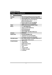
... y Dual Channel memory bus y Registered DDR2 533/667 y Supports 512MB, 1GB, 2GB and 4GB memory y ITE IT8716F-S y 2 PCI slots 32-Bit/33MHz (3.3V) y 1 PCI-Express x8 slot (with x4 bandwidth) y 2 PCI-Express x16 slot (One with x8 bandwidth) y Built in NVIDIA ® 3600 MCP with Software RAID 0,1,0+1, 5 y Supports 6 SATA 3.0 Gb/s connectors y 1 ATA connector y 1 Floppy connector y 6 SATA 3.0 Gb/s connectors y 2 PS/2 connectors y 1 VGA y 1 Serial port (COM) y 6 x USB 2.0 (4 by cable) y 2 x LAN RJ45 4 English GA-3CESL3-RH Motherboard Chapter 1 Introduction 1.1 Features Summary Form Factor CPU...
... y Dual Channel memory bus y Registered DDR2 533/667 y Supports 512MB, 1GB, 2GB and 4GB memory y ITE IT8716F-S y 2 PCI slots 32-Bit/33MHz (3.3V) y 1 PCI-Express x8 slot (with x4 bandwidth) y 2 PCI-Express x16 slot (One with x8 bandwidth) y Built in NVIDIA ® 3600 MCP with Software RAID 0,1,0+1, 5 y Supports 6 SATA 3.0 Gb/s connectors y 1 ATA connector y 1 Floppy connector y 6 SATA 3.0 Gb/s connectors y 2 PS/2 connectors y 1 VGA y 1 Serial port (COM) y 6 x USB 2.0 (4 by cable) y 2 x LAN RJ45 4 English GA-3CESL3-RH Motherboard Chapter 1 Introduction 1.1 Features Summary Form Factor CPU...
Manual
Page 5
..., VCC3 (3.3V) , VBAT3V, +5VSB, CPU1/2 Temperature, and System Temperature Values viewing y CPU/Power/System Fan Revolution Detect y CPU shutdown when overheat y System Voltage Detect y Dual Marvell® 88E1116 GbE PHY y Supports WOL, PXE y Phoenix BIOS on 8Mb flash ROM y PS/2 Mouse wake up from S1 under Windows Operating System y External Modem wake up y Supports S1, S4, S5 under Windows Operating System y Wake on LAN (WOL) y Wake on Ring (WOR) y AC Recovery y Supports Console Redirection y Supports 4-pin Fan controller 5
..., VCC3 (3.3V) , VBAT3V, +5VSB, CPU1/2 Temperature, and System Temperature Values viewing y CPU/Power/System Fan Revolution Detect y CPU shutdown when overheat y System Voltage Detect y Dual Marvell® 88E1116 GbE PHY y Supports WOL, PXE y Phoenix BIOS on 8Mb flash ROM y PS/2 Mouse wake up from S1 under Windows Operating System y External Modem wake up y Supports S1, S4, S5 under Windows Operating System y Wake on LAN (WOL) y Wake on Ring (WOR) y AC Recovery y Supports Console Redirection y Supports 4-pin Fan controller 5
Manual
Page 6
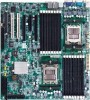
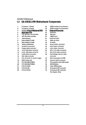
... Lan Ports 31. RJ45 Lan Ports 32. CPU 1 fan cable connector 37. CPU 2 fan cable connector 38. Intrusion cable connector 41. XGI Z9s VGA controller 7. Floppy cable connector 13 . Front USB cable connector 15. PCI Slot(32bit/33MHz) 21. PCI-E x16 Slot 22. DDR2 sockets for power supply 18. USB2.0 port 30. ID switch 33. 24-pin Power connector 34. 8-pin Power connector 35. 4-pin Power connector 36. Clear CMOS jumper 44. Front panel LED connector 45. Front USB cable connector 14. IDE cable connector 17. Serial port 28. English GA-3CESL3-RH Motherboard 1.2 GA...
... Lan Ports 31. RJ45 Lan Ports 32. CPU 1 fan cable connector 37. CPU 2 fan cable connector 38. Intrusion cable connector 41. XGI Z9s VGA controller 7. Floppy cable connector 13 . Front USB cable connector 15. PCI Slot(32bit/33MHz) 21. PCI-E x16 Slot 22. DDR2 sockets for power supply 18. USB2.0 port 30. ID switch 33. 24-pin Power connector 34. 8-pin Power connector 35. 4-pin Power connector 36. Clear CMOS jumper 44. Front panel LED connector 45. Front USB cable connector 14. IDE cable connector 17. Serial port 28. English GA-3CESL3-RH Motherboard 1.2 GA...
Manual
Page 8
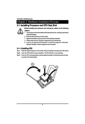
... make sure the CPU type is properly placed, please replace the plastic covering and push the metal lever back into the socket. 3. Never force the processor into locked position. 3 1 2 8 Remove the plastic covering on the socket. Step 2 Insert the CPU with the correct orientation. English GA-3CESL3-RH Motherboard Chapter 2 Hardware Installation Process 2-1: Installing Processor and CPU Haet Sink Before installing the processor and cooling fan, adhere to the...
... make sure the CPU type is properly placed, please replace the plastic covering and push the metal lever back into the socket. 3. Never force the processor into locked position. 3 1 2 8 Remove the plastic covering on the socket. Step 2 Insert the CPU with the correct orientation. English GA-3CESL3-RH Motherboard Chapter 2 Hardware Installation Process 2-1: Installing Processor and CPU Haet Sink Before installing the processor and cooling fan, adhere to the...
Manual
Page 10
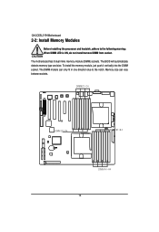
Memory size can only fit in one direction due to the following warning: When DIMM LED is ON, do not install/remove DIMM from socket. The BIOS will automatically detects memory type and size. To install the memory module, just push it vertically into the DIMM socket .The DIMM module can vary between sockets. DIMMC1~C4 DIMM D1~D4 DIMM B1~B4 DIMM A1~A4 10 English GA-3CESL3-RH Motherboard 2-2: Install Memory Modules Before installing the processor and heatsink, adhere to the notch. The motherboard has 8 dual inline memory module (DIMM) sockets.
Memory size can only fit in one direction due to the following warning: When DIMM LED is ON, do not install/remove DIMM from socket. The BIOS will automatically detects memory type and size. To install the memory module, just push it vertically into the DIMM socket .The DIMM module can vary between sockets. DIMMC1~C4 DIMM D1~D4 DIMM B1~B4 DIMM A1~A4 10 English GA-3CESL3-RH Motherboard 2-2: Install Memory Modules Before installing the processor and heatsink, adhere to the notch. The motherboard has 8 dual inline memory module (DIMM) sockets.
Manual
Page 14
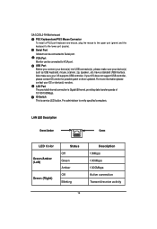
... 14 have a standard USB interface. Serial Port Modem can be connected to VGA port. USB Port Before you connect your device(s) into USB connector(s), please make sure your device(s) such as USB keyboard, mouse, scanner, zip, speaker...etc. For administraor to the lower port (purple). Also make sure your OS supports USB controller. English GA-3CESL3-RH Motherboard PS/2 Keyboard and PS/2 Mouse Connector To install a PS/2 port keyboard and mouse, plug the mouse to the upper port (green) and the...
... 14 have a standard USB interface. Serial Port Modem can be connected to VGA port. USB Port Before you connect your device(s) into USB connector(s), please make sure your device(s) such as USB keyboard, mouse, scanner, zip, speaker...etc. For administraor to the lower port (purple). Also make sure your OS supports USB controller. English GA-3CESL3-RH Motherboard PS/2 Keyboard and PS/2 Mouse Connector To install a PS/2 port keyboard and mouse, plug the mouse to the upper port (green) and the...
Manual
Page 16
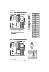
English GA-3CESL3-RH Motherboard 1) ATX_L1 (24-pin Auxiliary Power Connector) 24 12 AC power cord should only be connected to your power supply unit after ATX power cable and other related devices are firmly connected to the mainboard. 1 13 2 ) ATX_12V1 (8-pin Auxiliary Power Connector) PIN No.... 1 2 3 4 5 6 7 8 9 10 11 12 13 14 15 16 17 18 19 20 21 22 23 24 Definition +3.3V +3.3V GND +5V GND +5V GND POK 5VSB +12V +12V +3.3V +3.3V -12V GND PSON GND GND GND -5V +5V +5V +5V GND 15 This connector (ATX +12V) is used only for CPU Core Voltage. 16 48 Pin...
English GA-3CESL3-RH Motherboard 1) ATX_L1 (24-pin Auxiliary Power Connector) 24 12 AC power cord should only be connected to your power supply unit after ATX power cable and other related devices are firmly connected to the mainboard. 1 13 2 ) ATX_12V1 (8-pin Auxiliary Power Connector) PIN No.... 1 2 3 4 5 6 7 8 9 10 11 12 13 14 15 16 17 18 19 20 21 22 23 24 Definition +3.3V +3.3V GND +5V GND +5V GND POK 5VSB +12V +12V +3.3V +3.3V -12V GND PSON GND GND GND -5V +5V +5V +5V GND 15 This connector (ATX +12V) is used only for CPU Core Voltage. 16 48 Pin...
Manual
Page 18
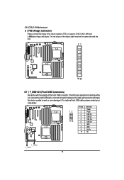
... while you connect the front USB cable, incorrect connection between the cable and connector will make the device unable to FDD. It supports 720K,1.2M,1.44M and 2.88Mbytes floppy disk types. For optional front USB cable, please contact your local dealer. 12 9 10 Pin No. 1 2 3 4 5 6 7 8 9 10 Definition Power Power USB DxUSB DyUSB Dx+ USB Dy+ GND GND No Pin NC F_USB2 F_USB1 18 English GA-3CESL3-RH Motherboard 5 ) FDD (Floppy Connector) Please connect the floppy drive ribbon cables to work or...
... while you connect the front USB cable, incorrect connection between the cable and connector will make the device unable to FDD. It supports 720K,1.2M,1.44M and 2.88Mbytes floppy disk types. For optional front USB cable, please contact your local dealer. 12 9 10 Pin No. 1 2 3 4 5 6 7 8 9 10 Definition Power Power USB DxUSB DyUSB Dx+ USB Dy+ GND GND No Pin NC F_USB2 F_USB1 18 English GA-3CESL3-RH Motherboard 5 ) FDD (Floppy Connector) Please connect the floppy drive ribbon cables to work or...
Manual
Page 20
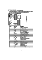
... Hard Disk LED Signal anode (+) System Fan Fail LED Signal Hard Disk LED Signal cathode(-) System Status LED Signal Power Button Signal anode (+) LAN1 access LED Signal Power Button Ground LAN1 linked LED Signal cathode(-) Reset Button cathode(-) SMBus Data Reset Button Ground SMBus Clock ID Switch Signal cathode(-) Chassis intrusion Signal ID Switch Ground LAN2 access LED Signal NMI Switch cathode(-) LAN2 linked LED Signal cathode(-) 20 English GA-3CESL3-RH Motherboard 15 ) F_Panel (2X12 Pins Front Panel connector) Please connect the power LED, PC speaker, reset switch and power switch...
... Hard Disk LED Signal anode (+) System Fan Fail LED Signal Hard Disk LED Signal cathode(-) System Status LED Signal Power Button Signal anode (+) LAN1 access LED Signal Power Button Ground LAN1 linked LED Signal cathode(-) Reset Button cathode(-) SMBus Data Reset Button Ground SMBus Clock ID Switch Signal cathode(-) Chassis intrusion Signal ID Switch Ground LAN2 access LED Signal NMI Switch cathode(-) LAN2 linked LED Signal cathode(-) 20 English GA-3CESL3-RH Motherboard 15 ) F_Panel (2X12 Pins Front Panel connector) Please connect the power LED, PC speaker, reset switch and power switch...

Manual
Page 22
English GA-3CESL3-RH Motherboard 17) PS1 (SMBUS connector for power supply) 1 Pin No. Definition 1 SMBus Clock 2 SMBUS Data 3 SMBUS Alert 4 GND 5 3.3V 18/19 ) CPU1_FAN/CPU2_FAN (CPU0/1 fan cable connectors) Please note, a proper installation of the CPU cooler is essential to 1A . 1 1 CPU2_FAN Pin No. 1 2 3 4 Definition GND 12V Sense Control CPU1_FAN 22 current up to prevent the CPU from running under abnormal condition or damaged by overheating.The CPU fan connector supports Max.
English GA-3CESL3-RH Motherboard 17) PS1 (SMBUS connector for power supply) 1 Pin No. Definition 1 SMBus Clock 2 SMBUS Data 3 SMBUS Alert 4 GND 5 3.3V 18/19 ) CPU1_FAN/CPU2_FAN (CPU0/1 fan cable connectors) Please note, a proper installation of the CPU cooler is essential to 1A . 1 1 CPU2_FAN Pin No. 1 2 3 4 Definition GND 12V Sense Control CPU1_FAN 22 current up to prevent the CPU from running under abnormal condition or damaged by overheating.The CPU fan connector supports Max.
Manual
Page 23
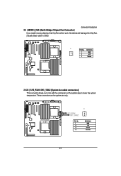
Sometimes will not work. SYS_FAN1 SYS_FAN2 Pin No. 1 2 3 4 1 Definition GND 12V Sense Control 23 Connector Introduction 20 ) MCP55_FAN (North Bridge Chipset Fan Connector) If you to link with the cooling fan on the system case to lower the system temperature. These connectors are for system use only. Definition 1 GND 2 +12V 3 Sense 21/22 ) SYS_FAN1/SYS_FAN2 (System fan cable connectors) This connector allows you install in wrong direction, the Chip Fan will damage the Chip Fan. (Usually black cable is GND) 1 Pin No.
Sometimes will not work. SYS_FAN1 SYS_FAN2 Pin No. 1 2 3 4 1 Definition GND 12V Sense Control 23 Connector Introduction 20 ) MCP55_FAN (North Bridge Chipset Fan Connector) If you to link with the cooling fan on the system case to lower the system temperature. These connectors are for system use only. Definition 1 GND 2 +12V 3 Sense 21/22 ) SYS_FAN1/SYS_FAN2 (System fan cable connectors) This connector allows you install in wrong direction, the Chip Fan will damage the Chip Fan. (Usually black cable is GND) 1 Pin No.

Manual
Page 24
English GA-3CESL3-RH Motherboard 23) BATTERY CAUTION Danger of used batteries according to the If you can use CLR_CMOS jumper to erase CMOS... Dispose of explosion if battery is incorrectly replaced. Replace only with the same or equivalent type recommended by the manufacturer. manufacturer's instructions. 1.Turn OFF the computer and unplug the power cord. 2.Remove the battery, wait for 30 second. 3.Re-install the battery. 4.Plug the power cord and turn ON the computer. 5.Or, you want to erase CMOS data 24
English GA-3CESL3-RH Motherboard 23) BATTERY CAUTION Danger of used batteries according to the If you can use CLR_CMOS jumper to erase CMOS... Dispose of explosion if battery is incorrectly replaced. Replace only with the same or equivalent type recommended by the manufacturer. manufacturer's instructions. 1.Turn OFF the computer and unplug the power cord. 2.Remove the battery, wait for 30 second. 3.Re-install the battery. 4.Plug the power cord and turn ON the computer. 5.Or, you want to erase CMOS data 24
Manual
Page 28
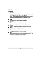
... GA-3CESL3-RH Motherboard GETTINGHELP Main Menu The on-line description of the highlighted setup function is displayed at the bottom of AMI special enhanced features. (ex: Auto detect fan and temperature status, automatically configure hard disk parameters.) z Security Change, set, or disable password. z Server Server additional features enabled/disabled setup menus. z Main This setup page includes all the items of first boot function features. z Advanced This setup page includes all the items of the screen...
... GA-3CESL3-RH Motherboard GETTINGHELP Main Menu The on-line description of the highlighted setup function is displayed at the bottom of AMI special enhanced features. (ex: Auto detect fan and temperature status, automatically configure hard disk parameters.) z Security Change, set, or disable password. z Server Server additional features enabled/disabled setup menus. z Main This setup page includes all the items of first boot function features. z Advanced This setup page includes all the items of the screen...

Manual
Page 33
... of CPU Type, CPU Speed, CPU1/CPU2 ID, CPU1/CPU2 L2 Cache, CPU Type, CPU Speed. Node Interleave Interleave memory blocks across nodes. Technology feature. Advanced Processor Option BIOS Setup This category includes the information of today's softwareonly virtual machine solutions. Setup menu for ccNUMA systems. (Default setting) Disabled Disable this function. (Default setting) ACPI SRAT Table Enabled Enable ACPI 2.0 static resources affinity table for AMD Virtualization (TM) Technology, Enhanced Virus Protection, Power Now Technology, Node Interleave, and ACPI SRAT...
... of CPU Type, CPU Speed, CPU1/CPU2 ID, CPU1/CPU2 L2 Cache, CPU Type, CPU Speed. Node Interleave Interleave memory blocks across nodes. Technology feature. Advanced Processor Option BIOS Setup This category includes the information of today's softwareonly virtual machine solutions. Setup menu for ccNUMA systems. (Default setting) Disabled Disable this function. (Default setting) ACPI SRAT Table Enabled Enable ACPI 2.0 static resources affinity table for AMD Virtualization (TM) Technology, Enhanced Virus Protection, Power Now Technology, Node Interleave, and ACPI SRAT...

Manual
Page 35
Save the changes and restart system. 35 GA-3CESL3-RH Motherboard Memory Configuration Figure 2-2: Memory Configuration Syetem Memory/Extended Memory /DIMM Information These category is display-only which is determined by POST (Power On Self Test) of the BIOS. Clear Disabled DIMMs Press [Enter] to clear the memory error status.
Save the changes and restart system. 35 GA-3CESL3-RH Motherboard Memory Configuration Figure 2-2: Memory Configuration Syetem Memory/Extended Memory /DIMM Information These category is display-only which is determined by POST (Power On Self Test) of the BIOS. Clear Disabled DIMMs Press [Enter] to clear the memory error status.
Manual
Page 38
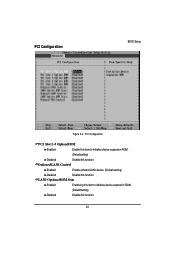
LAN1 Optiona ROM Scan Enabled Enableing this item to initialize device expansion ROM. (Defualt setting) Disabled Disable this function. 38 PCI Configuration BIOS Setup Figure 2-4: PCI Configuration PCI Slot 1~5 Option ROM Enabled Enable this item to initialize device expansion ROM. (Defualt setting) Disabled Disable this function. Onboard LAN1 Control Enabled Enable onboard LAN1 device. (Defualt setting) Disabled Disable this function.
LAN1 Optiona ROM Scan Enabled Enableing this item to initialize device expansion ROM. (Defualt setting) Disabled Disable this function. 38 PCI Configuration BIOS Setup Figure 2-4: PCI Configuration PCI Slot 1~5 Option ROM Enabled Enable this item to initialize device expansion ROM. (Defualt setting) Disabled Disable this function. Onboard LAN1 Control Enabled Enable onboard LAN1 device. (Defualt setting) Disabled Disable this function.

Manual
Page 40
Auto Auto-detection. (Default setting) 40 Auto Serial Port B Auto-detection. (Default setting) This allows users to configure serial prot B address by using this option. I/O Device Configuration BIOS Setup Figure 2-5: I/O Device Configuration Serial Port A This allows users to configure serial prot A address by using this option. Disabled No configuration. Disabled No configuration. Enabled Set serial port 2 address to 3F8/IRQ4. Enabled Set serial port A address to 2F8/IRQ3.
Auto Auto-detection. (Default setting) 40 Auto Serial Port B Auto-detection. (Default setting) This allows users to configure serial prot B address by using this option. I/O Device Configuration BIOS Setup Figure 2-5: I/O Device Configuration Serial Port A This allows users to configure serial prot A address by using this option. Disabled No configuration. Disabled No configuration. Enabled Set serial port 2 address to 3F8/IRQ4. Enabled Set serial port A address to 2F8/IRQ3.

Manual
Page 42
.... The hard disk will automatically detect HDD type. System will not work properly if you select User Type, related information will be provided in the computer. Such information should be asked to enter to F and SATA 0~SATA 5 are installed in the documentation form your drive must match with the drive table. GA-3CESL3-RH Motherboard IDE Configuration Figure 2-6: IDE Configuration Primary Master, Slave/SATA0~5 The category identifies the types of your hard disk vendor...
.... The hard disk will automatically detect HDD type. System will not work properly if you select User Type, related information will be provided in the computer. Such information should be asked to enter to F and SATA 0~SATA 5 are installed in the documentation form your drive must match with the drive table. GA-3CESL3-RH Motherboard IDE Configuration Figure 2-6: IDE Configuration Primary Master, Slave/SATA0~5 The category identifies the types of your hard disk vendor...


