
Owner's Manual
Page 4
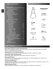
...to 60 Watts max. TABLE OF CONTENTS SECTION PAGE PRE-INSTALLATION CHECK LIST 2-3 4 TOOLS REQUIRED 4 SAFETY FEATURES 4 OPERATIONAL FEATURES 5 PARTS LISTS AND ILLUSTRATIONS 5-8 POWER HEAD 5 ONE-PIECE RAIL 6 THREE-PIECE RAIL 7 FASTENERS AND ACCESSORIES 8 SAFETY INFORMATION 9 PRE-INSTALLATION WARNING... ORDER FORM C RECOMMENDED TOOLS Carpenter's level Step ladder Adjustable wrench Pencil Drill 5/ 32" Drill Bit Ratchet Wire strippers Phillips screwdriver 7/16" and 9/16" Sockets Tape measure SAFETY FEATURES (varies by model) Safe-T-Beam® (STB) Non-Contact Reversing...
...to 60 Watts max. TABLE OF CONTENTS SECTION PAGE PRE-INSTALLATION CHECK LIST 2-3 4 TOOLS REQUIRED 4 SAFETY FEATURES 4 OPERATIONAL FEATURES 5 PARTS LISTS AND ILLUSTRATIONS 5-8 POWER HEAD 5 ONE-PIECE RAIL 6 THREE-PIECE RAIL 7 FASTENERS AND ACCESSORIES 8 SAFETY INFORMATION 9 PRE-INSTALLATION WARNING... ORDER FORM C RECOMMENDED TOOLS Carpenter's level Step ladder Adjustable wrench Pencil Drill 5/ 32" Drill Bit Ratchet Wire strippers Phillips screwdriver 7/16" and 9/16" Sockets Tape measure SAFETY FEATURES (varies by model) Safe-T-Beam® (STB) Non-Contact Reversing...
Owner's Manual
Page 5
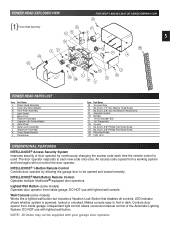
... OR GENIECOMPANY.COM 41 F R 5 G P 48 A 42 K L 45 39 M H 4 J N POWER HEAD PARTS LIST Item Part Name 1 Power Head Assembly A Cover (By Series/Model) B Front Plate Assembly C Light Socket D Motor Parts E Receiver Assembly F Capacitor (By Series/Model) G Opto Wheel H Opto-Luctor Assembly J Sequencer Assembly K Circuit Board Bracket ...L Transformer Item Part Name M Terminal Strip N No. 8-32 x 1/2" Hex Washer Head Screw P No. 8-32 x 3/8" Slot Hex Washer Head Screw R ...
... OR GENIECOMPANY.COM 41 F R 5 G P 48 A 42 K L 45 39 M H 4 J N POWER HEAD PARTS LIST Item Part Name 1 Power Head Assembly A Cover (By Series/Model) B Front Plate Assembly C Light Socket D Motor Parts E Receiver Assembly F Capacitor (By Series/Model) G Opto Wheel H Opto-Luctor Assembly J Sequencer Assembly K Circuit Board Bracket ...L Transformer Item Part Name M Terminal Strip N No. 8-32 x 1/2" Hex Washer Head Screw P No. 8-32 x 3/8" Slot Hex Washer Head Screw R ...
Owner's Manual
Page 6
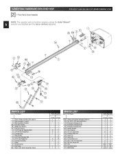
...9 22 15B 9 44 2 4 39 45 20 47 24 22 46 13 25 24 10 21 28 23 25 17 18 26 27 PARTS LIST Item Part Name 1 Power Head Assembly (See page 5) 2 Rail Assembly (1 piece) 3 Rail Assembly (3 piece) 3A First Rail Section 3B Middle Rail... Hex Flange Nut 10 Carriage Assembly 11 Collar 12 Retaining Clip 13 Rail Strap 15A Open Limit Switch Assembly (Grey) Parts Required 1 Piece 3-Piece 1 1 1 1 1 1 1 2 2 2 2 1 1 4 8 5 13 1 1 2 2 1 1 1 1 PARTS LIST Item Part Name 15B Close Limit Switch Assembly (Brown) 16 No. 8-32 x 3/8" Hex Head Screw 17 Emergency Release Cord 18...
...9 22 15B 9 44 2 4 39 45 20 47 24 22 46 13 25 24 10 21 28 23 25 17 18 26 27 PARTS LIST Item Part Name 1 Power Head Assembly (See page 5) 2 Rail Assembly (1 piece) 3 Rail Assembly (3 piece) 3A First Rail Section 3B Middle Rail... Hex Flange Nut 10 Carriage Assembly 11 Collar 12 Retaining Clip 13 Rail Strap 15A Open Limit Switch Assembly (Grey) Parts Required 1 Piece 3-Piece 1 1 1 1 1 1 1 2 2 2 2 1 1 4 8 5 13 1 1 2 2 1 1 1 1 PARTS LIST Item Part Name 15B Close Limit Switch Assembly (Brown) 16 No. 8-32 x 3/8" Hex Head Screw 17 Emergency Release Cord 18...
Owner's Manual
Page 7
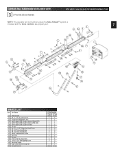
... 1 3A 4 8 7 22 15B 9 9 20 47 24 22 13 3C 46 25 26 21 3B 24 28 23 10 25 17 18 27 39 45 PARTS LIST Item Part Name 33 Wall Console 34 #6 x 1-1/4" Pan Head Screw 35 Entrapment WARNING Label 36 Safe-T-Beam (STB) System Sensor (Green LED) 37 Safe-T-Beam (STB... Clip 45 Bumper 46 5/16" x 3/4" Hex Head Bolt 47 1/4-20 x 3/4" Self-tapping Screw 48 Mounting Straps 49 Light Lens (Shown on page 5) 50 Remote Control Parts Required 1 Piece 3-Piece varies varies 2 2 1 1 1 1 1 1 2 2 1 1 4 4 4 4 2 2 1 1 4 4 1 1 5 5 3 3 2 1 1 varies varies
... 1 3A 4 8 7 22 15B 9 9 20 47 24 22 13 3C 46 25 26 21 3B 24 28 23 10 25 17 18 27 39 45 PARTS LIST Item Part Name 33 Wall Console 34 #6 x 1-1/4" Pan Head Screw 35 Entrapment WARNING Label 36 Safe-T-Beam (STB) System Sensor (Green LED) 37 Safe-T-Beam (STB... Clip 45 Bumper 46 5/16" x 3/4" Hex Head Bolt 47 1/4-20 x 3/4" Self-tapping Screw 48 Mounting Straps 49 Light Lens (Shown on page 5) 50 Remote Control Parts Required 1 Piece 3-Piece varies varies 2 2 1 1 1 1 1 1 2 2 1 1 4 4 4 4 2 2 1 1 4 4 1 1 5 5 3 3 2 1 1 varies varies
Owner's Manual
Page 8
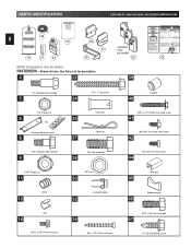
....354.3643 OR GENIECOMPANY.COM 29 8 35 36 19 31 33 remotes 37 vary by model 38 50 43 NOTE: Accessories vary by model. See Parts List for description. 4 22 39 1/4" Shoulder bolt w/flange 5 1/4" Flange nut 6 OR Carriage stop (not to scale) 8 5/16" Shoulder bolt w/flange 9 5/16" Flange nut 11 Collar...
....354.3643 OR GENIECOMPANY.COM 29 8 35 36 19 31 33 remotes 37 vary by model 38 50 43 NOTE: Accessories vary by model. See Parts List for description. 4 22 39 1/4" Shoulder bolt w/flange 5 1/4" Flange nut 6 OR Carriage stop (not to scale) 8 5/16" Shoulder bolt w/flange 9 5/16" Flange nut 11 Collar...
Owner's Manual
Page 9
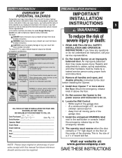
... the garage door. 7. Do Not connect the Opener to the power source until instructed to the wall button or console. This is moving parts. CAUTION means that follow, the words Danger, Warning, and Caution are used to indicate important steps to be made by a trained service... doors are large, heavy objects that severe injury or death can result from failure severe injury or death: to follow instructions. Since moving parts of 5', so small children cannot reach it. • Away from all locks connected to the door before removing operator cover. When replacing...
... the garage door. 7. Do Not connect the Opener to the power source until instructed to the wall button or console. This is moving parts. CAUTION means that follow, the words Danger, Warning, and Caution are used to indicate important steps to be made by a trained service... doors are large, heavy objects that severe injury or death can result from failure severe injury or death: to follow instructions. Since moving parts of 5', so small children cannot reach it. • Away from all locks connected to the door before removing operator cover. When replacing...

Owner's Manual
Page 10
... of screw against coupler. Fig. 1-1. 4. CAUTION Drive screws can slide out of shaft and rail attachment flange) is fully assembled. 5. SECT 1-MAIN ASSEMBLY OPEN BLUE PARTS BAG NOTE: 3-piece rail assembly is available. 1. An extension for 8 feet doors is for doors up to step 8. [39] Coupler [45] Rubber bumper Fig. 1-1 Fig...
... of screw against coupler. Fig. 1-1. 4. CAUTION Drive screws can slide out of shaft and rail attachment flange) is fully assembled. 5. SECT 1-MAIN ASSEMBLY OPEN BLUE PARTS BAG NOTE: 3-piece rail assembly is available. 1. An extension for 8 feet doors is for doors up to step 8. [39] Coupler [45] Rubber bumper Fig. 1-1 Fig...

Owner's Manual
Page 14
... and twist it to help maintain slack. Fig. 1-20. • "OPEN" limit switch [15A]. - Check that white lever is on carriage). - MAIN ASSEMBLY OPEN GREEN PARTS BAG Screws for use later. 14 14. Insert set aside for attaching light cover are included in this to help verify they are identical.) - Fig...
... and twist it to help maintain slack. Fig. 1-20. • "OPEN" limit switch [15A]. - Check that white lever is on carriage). - MAIN ASSEMBLY OPEN GREEN PARTS BAG Screws for use later. 14 14. Insert set aside for attaching light cover are included in this to help verify they are identical.) - Fig...

Owner's Manual
Page 16
With door held partly open (at its 16 highest point. Final header bracket mounting location. • For SECTIONAL DOORS- Measure from here to "highest point of travel . NOTE: Following ...
With door held partly open (at its 16 highest point. Final header bracket mounting location. • For SECTIONAL DOORS- Measure from here to "highest point of travel . NOTE: Following ...
Owner's Manual
Page 17
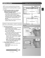
... out if there is finished (covered with drywall), continue with step 5. If your garage wall is wood behind mounting location. garage door opening OPEN ORANGE PARTS BAG TYPICAL FINISHED WALL floor Fig. 2-5 5. Fig. 2-7 and Fig. 2-5. 6. wall 17 studs 4. Fig. 2-5. Mount header bracket [20]. • Drill 5/32 inch pilot holes at marked...
... out if there is finished (covered with drywall), continue with step 5. If your garage wall is wood behind mounting location. garage door opening OPEN ORANGE PARTS BAG TYPICAL FINISHED WALL floor Fig. 2-5 5. Fig. 2-7 and Fig. 2-5. 6. wall 17 studs 4. Fig. 2-5. Mount header bracket [20]. • Drill 5/32 inch pilot holes at marked...
Owner's Manual
Page 21
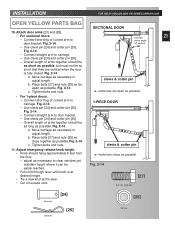
... at the lever. • Cut off vertical. Adjust emergency release knob height. • Knob should be 21 some angle off excess cord. INSTALLATION OPEN YELLOW PARTS BAG 10. Fig. 2-14. - Overall length of curved arm to carriage. - Use clevis pin [24] and cotter pin [25]. b. Connect short leg of arms together...
... at the lever. • Cut off vertical. Adjust emergency release knob height. • Knob should be 21 some angle off excess cord. INSTALLATION OPEN YELLOW PARTS BAG 10. Fig. 2-14. - Overall length of curved arm to carriage. - Use clevis pin [24] and cotter pin [25]. b. Connect short leg of arms together...
Owner's Manual
Page 22
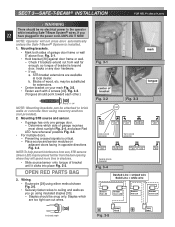
... should be substituted for extensions. • Center bracket on adjacent doors facing in opposite directions Fig. 3-4. Determine which are available at local dealer. OPEN RED PARTS BAG 3. may be placed further from sun, STB sensors (Green LED) may be no electrical power to brick walls or concrete floor using insulated staples...
... should be substituted for extensions. • Center bracket on adjacent doors facing in opposite directions Fig. 3-4. Determine which are available at local dealer. OPEN RED PARTS BAG 3. may be placed further from sun, STB sensors (Green LED) may be no electrical power to brick walls or concrete floor using insulated staples...

Owner's Manual
Page 23
... staples, make sure you fasten them only as tightly as shown Fig. 3-6. - Split and strip wire ends to be performed following . • Ensure that no part of door or its hardware is in path between lenses of source and sensor. • Ensure that tops of lenses are flexible, and can cause...
... staples, make sure you fasten them only as tightly as shown Fig. 3-6. - Split and strip wire ends to be performed following . • Ensure that no part of door or its hardware is in path between lenses of source and sensor. • Ensure that tops of lenses are flexible, and can cause...

Owner's Manual
Page 24
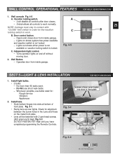
...- 1.800.354.3643 WARNING Power must be un-lighted. At least 5 feet from floor, so small children cannot reach it. • Route wire from moving parts. - Tighten screws • Connect wires to malfunction.
...- 1.800.354.3643 WARNING Power must be un-lighted. At least 5 feet from floor, so small children cannot reach it. • Route wire from moving parts. - Tighten screws • Connect wires to malfunction.
Owner's Manual
Page 25
... cover hooks into slots at bottom of lens Fig. 5-2 [42] #8 x 3/8" Pan head screw NOTE: Carriage must stay in contact with 2 pan head screws. ([42] green parts bag). Lights on and off without moving door. 2. Whenever possible, use short neck bulbs. - Check for the vacation locking switch to work . Opens and closes...
... cover hooks into slots at bottom of lens Fig. 5-2 [42] #8 x 3/8" Pan head screw NOTE: Carriage must stay in contact with 2 pan head screws. ([42] green parts bag). Lights on and off without moving door. 2. Whenever possible, use short neck bulbs. - Check for the vacation locking switch to work . Opens and closes...
Owner's Manual
Page 27
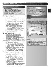
..., move adjusting screws. • Run operator using wall control. • Observe door runs to new position between door and carriage. - Adjust opening force by moving parts. Set limit switch position. • Check door fully closed . 3. Slide "CLOSE" limit switch back toward Powerhead until door runs to operate door. If not, move...
..., move adjusting screws. • Run operator using wall control. • Observe door runs to new position between door and carriage. - Adjust opening force by moving parts. Set limit switch position. • Check door fully closed . 3. Slide "CLOSE" limit switch back toward Powerhead until door runs to operate door. If not, move...
Owner's Manual
Page 29
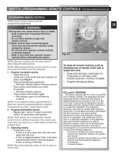
... These limits are designed to provide reasonable protection against harmful interference in a particular installation. If this equipment does cause harmful interference to Part 15 of the FCC Rules. SECT 9-PROGRAMMING REMOTE CONTROLS FOR HELP-GENIECOMPANY.COM PROGRAMMING REMOTE CONTROLS NOTE: Each remote device must be... separately WARNING Learn Button 29 Moving door can radiate radio frequency energy and, if not installed and used in accordance with FCC Part 15 and RSS 210 of open or close door if Safe-T-Beam® malfunctions. NOTE: Each button on a circuit different ...
... These limits are designed to provide reasonable protection against harmful interference in a particular installation. If this equipment does cause harmful interference to Part 15 of the FCC Rules. SECT 9-PROGRAMMING REMOTE CONTROLS FOR HELP-GENIECOMPANY.COM PROGRAMMING REMOTE CONTROLS NOTE: Each remote device must be... separately WARNING Learn Button 29 Moving door can radiate radio frequency energy and, if not installed and used in accordance with FCC Part 15 and RSS 210 of open or close door if Safe-T-Beam® malfunctions. NOTE: Each button on a circuit different ...
