

Owner's Manual
Page 1
... 25 Troubleshooting 26 Wiring Diagram 29 Warranty information 30 COMPLETE WITH INTELLICODE® REMOTE CONTROL AND SERIES II ELECTRONICS For 7' 6" Doors. SAVEFTUHTIUSRMEARNEUFEARLEFNOCRE Please call us: 1-800-35-GENIE (354-3643) www.geniecompany.com Please have Model information ready when calling. 3531835447 TABLE OF CONTENTS Safety Information 2 Important Installation Instructions 2 Safety Features 2 Pre...
... 25 Troubleshooting 26 Wiring Diagram 29 Warranty information 30 COMPLETE WITH INTELLICODE® REMOTE CONTROL AND SERIES II ELECTRONICS For 7' 6" Doors. SAVEFTUHTIUSRMEARNEUFEARLEFNOCRE Please call us: 1-800-35-GENIE (354-3643) www.geniecompany.com Please have Model information ready when calling. 3531835447 TABLE OF CONTENTS Safety Information 2 Important Installation Instructions 2 Safety Features 2 Pre...

Owner's Manual
Page 2
... door to , the emergency release 8 The operator must reverse when the door contacts a 1-1/2 inch high object on the floor at 1-800-35-GENIE.. An improperly balanced door could cause severe injury. Install the emergency release tag on when door is moving objects, springs under high tension ..., call your service representative. 2 Do Not install operator on you have any questions or do not understand the information presented, call 1-800-35-GENIE or visit www.geniecompany.com Force Guard® Control Used to fully open position if anything to the fully open and close within 2...
... door to , the emergency release 8 The operator must reverse when the door contacts a 1-1/2 inch high object on the floor at 1-800-35-GENIE.. An improperly balanced door could cause severe injury. Install the emergency release tag on when door is moving objects, springs under high tension ..., call your service representative. 2 Do Not install operator on you have any questions or do not understand the information presented, call 1-800-35-GENIE or visit www.geniecompany.com Force Guard® Control Used to fully open position if anything to the fully open and close within 2...
Owner's Manual
Page 3
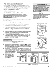
...CONDITION AND THICKNESS Check condition of vertical stile in most garage doors. Center Stile Figure 2 Note Door Type For Help, call 1-800-35-GENIE or visit www.geniecompany.com 3 See Troubleshooting Guide on a properly braced sectional door or solidly braced one -piece Torsion Springs ...Center Stile Extension Springs Header Area door (Figure 2). Make a note of whether it moves freely (Figure 1). D Contact your Genie Factory Authorized Dealer or dealer of your door is a sectional or a one -piece door. PRE-INSTALLATION CHECKLIST This Opener includes parts and...
...CONDITION AND THICKNESS Check condition of vertical stile in most garage doors. Center Stile Figure 2 Note Door Type For Help, call 1-800-35-GENIE or visit www.geniecompany.com 3 See Troubleshooting Guide on a properly braced sectional door or solidly braced one -piece Torsion Springs ...Center Stile Extension Springs Header Area door (Figure 2). Make a note of whether it moves freely (Figure 1). D Contact your Genie Factory Authorized Dealer or dealer of your door is a sectional or a one -piece door. PRE-INSTALLATION CHECKLIST This Opener includes parts and...
Owner's Manual
Page 4
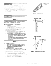
... door and header: • Close door. • Measure door width at top. • Mark a point at 1-800-35-GENIE. For one-piece doors, add 6" to new mounting board. A Find vertical center line of door and on header directly... above the Header Bracket mounting point, contact a Genie Factory Authorized Dealer. • If a door spring is not at least two Lag Screws and Flat Washers (not provided).... the Header Bracket avove the spring. Bottom of Travel 4 For Help, call 1-800-35-GENIE or visit www.geniecompany.com
... door and header: • Close door. • Measure door width at top. • Mark a point at 1-800-35-GENIE. For one-piece doors, add 6" to new mounting board. A Find vertical center line of door and on header directly... above the Header Bracket mounting point, contact a Genie Factory Authorized Dealer. • If a door spring is not at least two Lag Screws and Flat Washers (not provided).... the Header Bracket avove the spring. Bottom of Travel 4 For Help, call 1-800-35-GENIE or visit www.geniecompany.com
Owner's Manual
Page 5
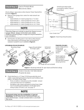
...beam and finished ceilings Check Step 6: CHECK CEILING FOR GROUNDED POWER SOURCE A Check that there is a Licensed Electrician. Not all Genie Factory Authorized Dealers are included to attach the Opener to install appropriate wiring in place of materials needed for your installation (Figure ...Permanent wiring must be installed. Additional mounting straps or angle iron may be needed for your installation. For Help, call 1-800-35-GENIE or visit www.geniecompany.com 5 NOTE Mounting Straps are Licensed Electricians. Check Step 5: CHECK POWER HEAD MOUNTING AREA Check ceiling...
...beam and finished ceilings Check Step 6: CHECK CEILING FOR GROUNDED POWER SOURCE A Check that there is a Licensed Electrician. Not all Genie Factory Authorized Dealers are included to attach the Opener to install appropriate wiring in place of materials needed for your installation (Figure ...Permanent wiring must be installed. Additional mounting straps or angle iron may be needed for your installation. For Help, call 1-800-35-GENIE or visit www.geniecompany.com 5 NOTE Mounting Straps are Licensed Electricians. Check Step 5: CHECK POWER HEAD MOUNTING AREA Check ceiling...
Owner's Manual
Page 6
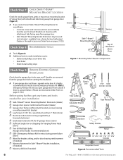
...bits • Stud finder • Sheet-metal cutting snips Top of 6" Bracket 6" above floor) with attachment tabs facing away from a Genie Factory Authorized Dealer or through Accessories Order Form on pages 31/32). Check Step 7: CHECK SAFE-T-BEAM® MOUNTING BRACKET LOCATION Check for... Stripper Pencil Hack Saw 1/4" 5/16" 3/8" 7/16" 1/2" 9/16" Sockets Carpenter's Level Figure 8 Recommended Tools 6 For Help, call 1-800-35-GENIE or visit www.geniecompany.com A If you open garage door from outside if there is highly recommended to mount Brackets on masonry with attachment tabs...
...bits • Stud finder • Sheet-metal cutting snips Top of 6" Bracket 6" above floor) with attachment tabs facing away from a Genie Factory Authorized Dealer or through Accessories Order Form on pages 31/32). Check Step 7: CHECK SAFE-T-BEAM® MOUNTING BRACKET LOCATION Check for... Stripper Pencil Hack Saw 1/4" 5/16" 3/8" 7/16" 1/2" 9/16" Sockets Carpenter's Level Figure 8 Recommended Tools 6 For Help, call 1-800-35-GENIE or visit www.geniecompany.com A If you open garage door from outside if there is highly recommended to mount Brackets on masonry with attachment tabs...

Owner's Manual
Page 7
... Motor Drive Board Controller Board No. 10-24 x 3/8" Hex Head No. 8-32 x 1" Phillips Screw No. 8-32 x 3/8" Slotted Hex Head Screw Power Cord For Help, call 1-800-35-GENIE or visit www.geniecompany.com 7 These items will be illustrated throughout the manual as required.
... Motor Drive Board Controller Board No. 10-24 x 3/8" Hex Head No. 8-32 x 1" Phillips Screw No. 8-32 x 3/8" Slotted Hex Head Screw Power Cord For Help, call 1-800-35-GENIE or visit www.geniecompany.com 7 These items will be illustrated throughout the manual as required.
Owner's Manual
Page 8
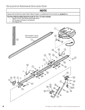
One-Piece Rail Assembly (Genie Pro only) for 10' or 12' door includes: • Special "Close" Limit Switch with longer Wires. • 96" Emergency Release Cord (yellow). • Rail Support ... 22 99 45A 1100 46B 3311 30 28 556 3322 3366 3344 333 32 112 3333 2225 2222 23 2244 3355 8 For Help, call 1-800-35-GENIE or visit www.geniecompany.com EXCELERATOR HARDWARE EXPLODED VIEW NOTE Opener will not function unless Safe-T-Beam® System is installed and Force Controls are...
One-Piece Rail Assembly (Genie Pro only) for 10' or 12' door includes: • Special "Close" Limit Switch with longer Wires. • 96" Emergency Release Cord (yellow). • Rail Support ... 22 99 45A 1100 46B 3311 30 28 556 3322 3366 3344 333 32 112 3333 2225 2222 23 2244 3355 8 For Help, call 1-800-35-GENIE or visit www.geniecompany.com EXCELERATOR HARDWARE EXPLODED VIEW NOTE Opener will not function unless Safe-T-Beam® System is installed and Force Controls are...
Owner's Manual
Page 9
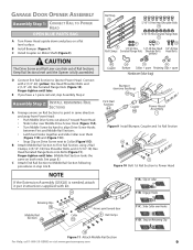
... a flat level surface. Assembly Step C2H: INSTALL REMAINING RAIL SECTIONS A Arrange arrows on Retaining Clip 10 Figure 11 Attach Middle Rail Section For Help, call 1-800-35-GENIE or visit www.geniecompany.com 9 D Connect first Rail Section to First Rail Section, using 2 Rail Clamps, 4 (5/16"-18) Hex Shoulder Bolts, and 4 (5/16"-18...
... a flat level surface. Assembly Step C2H: INSTALL REMAINING RAIL SECTIONS A Arrange arrows on Retaining Clip 10 Figure 11 Attach Middle Rail Section For Help, call 1-800-35-GENIE or visit www.geniecompany.com 9 D Connect first Rail Section to First Rail Section, using 2 Rail Clamps, 4 (5/16"-18) Hex Shoulder Bolts, and 4 (5/16"-18...

Owner's Manual
Page 10
... ONTO RAILS A Place Magnetic Carriage Assembly Lever in "release" position. Insert (#8-32 x 1") Hex Head Screw into slot on Assembled Rail 10 For Help, call 1-800-35-GENIE or visit www.geniecompany.com B Uncoil Limit Switch Wires and retain Twist Ties. #8-32 x 1" Hex Head Screws Open Limit Switch Assembly 22 Wire Clips 53...
... ONTO RAILS A Place Magnetic Carriage Assembly Lever in "release" position. Insert (#8-32 x 1") Hex Head Screw into slot on Assembled Rail 10 For Help, call 1-800-35-GENIE or visit www.geniecompany.com B Uncoil Limit Switch Wires and retain Twist Ties. #8-32 x 1" Hex Head Screws Open Limit Switch Assembly 22 Wire Clips 53...

Owner's Manual
Page 11
... Carriage Assembly Release Lever (Figure 16). Antenna Terminal Block White Limit Brown Limit Switch wires Switch wires Figure 15 Connect Limit Switch Wires to call 1-800-35-GENIE or visit www.geniecompany.com 11 D Attach Emergency Release Tag to Magnetic Carriage Assembly Release Lever. 25 Emergency Release Tag Assembly Step C8H: RECORD...
... Carriage Assembly Release Lever (Figure 16). Antenna Terminal Block White Limit Brown Limit Switch wires Switch wires Figure 15 Connect Limit Switch Wires to call 1-800-35-GENIE or visit www.geniecompany.com 11 D Attach Emergency Release Tag to Magnetic Carriage Assembly Release Lever. 25 Emergency Release Tag Assembly Step C8H: RECORD...
Owner's Manual
Page 12
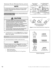
... Head Bolts 11 5/16-18 x 3/4" Hex Serrated Flange Nuts 28 Door Bracket 56 1/4"-20 x 3/4" Self-Drilling Screws Hardware (orange bag) 12 For Help, call 1-800-35-GENIE or visit www.geniecompany.com Installation SteCpH1: INSTALL HEADER BRACKET Mount directly into header Center Line of door Use of Header Bracket support board Center...
... Head Bolts 11 5/16-18 x 3/4" Hex Serrated Flange Nuts 28 Door Bracket 56 1/4"-20 x 3/4" Self-Drilling Screws Hardware (orange bag) 12 For Help, call 1-800-35-GENIE or visit www.geniecompany.com Installation SteCpH1: INSTALL HEADER BRACKET Mount directly into header Center Line of door Use of Header Bracket support board Center...

Owner's Manual
Page 13
... supporting the Power Head, place threaded end of the included Lag Screws vs. B Attach (5/16"-18) Flange Nut to Header Bracket For Help, call 1-800-35-GENIE or visit www.geniecompany.com 13 Installation SteCpH2: INSTALL GARAGE DOOR BRACKET CAUTION Doors made of door Attach no lower than top roller, and mark...
... supporting the Power Head, place threaded end of the included Lag Screws vs. B Attach (5/16"-18) Flange Nut to Header Bracket For Help, call 1-800-35-GENIE or visit www.geniecompany.com 13 Installation SteCpH2: INSTALL GARAGE DOOR BRACKET CAUTION Doors made of door Attach no lower than top roller, and mark...

Owner's Manual
Page 14
... finder or similar device. 55 11 Attach angle iron (not included) to garage ceiling. Check for open beam and finished ceilings 14 For Help, call 1-800-35-GENIE or visit www.geniecompany.com Extra material may vary. Read all fasteners now.
... finder or similar device. 55 11 Attach angle iron (not included) to garage ceiling. Check for open beam and finished ceilings 14 For Help, call 1-800-35-GENIE or visit www.geniecompany.com Extra material may vary. Read all fasteners now.

Owner's Manual
Page 15
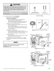
... Arm Figure 23 Assemble Arms (SECTIONAL) As long as possible 35 32 Curved 36 34 Door Arm 31 Straight Door Arm 33 For Help, call 1-800-35-GENIE or visit www.geniecompany.com Figure 24 Assemble Arms (ONE-PIECE) 15
... Arm Figure 23 Assemble Arms (SECTIONAL) As long as possible 35 32 Curved 36 34 Door Arm 31 Straight Door Arm 33 For Help, call 1-800-35-GENIE or visit www.geniecompany.com Figure 24 Assemble Arms (ONE-PIECE) 15

Owner's Manual
Page 16
... 26 Source/sensor Locations Top edge of garage door frame or wall 6" above floor Figure 27 Final Check Safe-T-Beams® 16 For Help, call 1-800-35-GENIE or visit www.geniecompany.com B Attach Safe-T-Beam® Source (Red LED) and Sensor (Green LED) to brick walls or concrete floor using masonry... installed. Installation SteCpH6: INSTALL SAFE-T-BEAM® SYSTEM ELECTRICAL WARNING Ensure there is critical. - If not, Safe-TBeam® Mounting Bracket Extensions are available from a Genie Factory Authorized Dealer or through the Accessories Order Form. -
... 26 Source/sensor Locations Top edge of garage door frame or wall 6" above floor Figure 27 Final Check Safe-T-Beams® 16 For Help, call 1-800-35-GENIE or visit www.geniecompany.com B Attach Safe-T-Beam® Source (Red LED) and Sensor (Green LED) to brick walls or concrete floor using masonry... installed. Installation SteCpH6: INSTALL SAFE-T-BEAM® SYSTEM ELECTRICAL WARNING Ensure there is critical. - If not, Safe-TBeam® Mounting Bracket Extensions are available from a Genie Factory Authorized Dealer or through the Accessories Order Form. -
Owner's Manual
Page 17
... Wiring Method A Leave slack for adjustment Terminal attachments at Power Head Figure 29 Wiring Method A Wire Clips 53 Insulated Staples 38 For Help, call 1-800-35-GENIE or visit www.geniecompany.com 654321 STB Terminal attachments at Safe-T-Beam® Terminal attachments at Power Head. - NOTE The Safe-T-Beam® alignment check...
... Wiring Method A Leave slack for adjustment Terminal attachments at Power Head Figure 29 Wiring Method A Wire Clips 53 Insulated Staples 38 For Help, call 1-800-35-GENIE or visit www.geniecompany.com 654321 STB Terminal attachments at Safe-T-Beam® Terminal attachments at Power Head. - NOTE The Safe-T-Beam® alignment check...

Owner's Manual
Page 18
... position. B Find a convenient mounting location: • Within direct sight of garage door. • At least 5' above with Entrapment Warning Label 18 For Help, call 1-800-35-GENIE or visit www.geniecompany.com D Wire Wall Console to Opener (Figure 32): • On Power Head, connect Striped Wire to Terminal #1 and White Wire to...
... position. B Find a convenient mounting location: • Within direct sight of garage door. • At least 5' above with Entrapment Warning Label 18 For Help, call 1-800-35-GENIE or visit www.geniecompany.com D Wire Wall Console to Opener (Figure 32): • On Power Head, connect Striped Wire to Terminal #1 and White Wire to...
Owner's Manual
Page 19
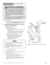
... code requires Opener be properly grounded to prevent personal injury and damage to the components. • The electrical power to page 26.) For Help, call 1-800-35-GENIE or visit www.geniecompany.com 19 D Perform Safe-T-Beam® alignment check: • Check if Safe-T-Beam® Source Red LED is glowing continuously...
... code requires Opener be properly grounded to prevent personal injury and damage to the components. • The electrical power to page 26.) For Help, call 1-800-35-GENIE or visit www.geniecompany.com 19 D Perform Safe-T-Beam® alignment check: • Check if Safe-T-Beam® Source Red LED is glowing continuously...
Owner's Manual
Page 20
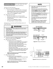
...) Magnet Figure 34 Setting Limit Switches Force Controls HI LO HI LO OPEN CLOSE FORCE FORCE Figure 35 Making Force Adjustments 20 For Help, call 1-800-35-GENIE or visit www.geniecompany.com B Setting Open Limit Switch: • Manually open garage door to run, move , check Safe-T-Beam® System. B Adjust the...
...) Magnet Figure 34 Setting Limit Switches Force Controls HI LO HI LO OPEN CLOSE FORCE FORCE Figure 35 Making Force Adjustments 20 For Help, call 1-800-35-GENIE or visit www.geniecompany.com B Setting Open Limit Switch: • Manually open garage door to run, move , check Safe-T-Beam® System. B Adjust the...