
Owner's Manual
Page 6
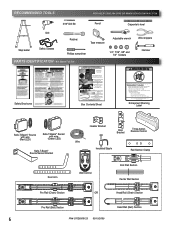
...Manual for easy access. Procéder selon les instructions stipumléoenstadgaenàs sleuimvraen.uel d'installation pour les étapes de Box Contents Sheet Adjustable wrench Wire strippers 1/4", 7/16", 3/8" and 1/2" Sockets Hammer Child can result. • Never let child walk or...y accéder facilement. Mount wall control out of child's reach (at least 5 feet above floor). RECOMMENDED TOOLS FOR HELP-1.800.354.3643 OR WWW.GENIECOMPANY.COM 3/16" Drill Bit Pencil Carpenter's level Drill Step ladder Safety Glasses Ratchet Tape measure Phillips screwdriver ...
...Manual for easy access. Procéder selon les instructions stipumléoenstadgaenàs sleuimvraen.uel d'installation pour les étapes de Box Contents Sheet Adjustable wrench Wire strippers 1/4", 7/16", 3/8" and 1/2" Sockets Hammer Child can result. • Never let child walk or...y accéder facilement. Mount wall control out of child's reach (at least 5 feet above floor). RECOMMENDED TOOLS FOR HELP-1.800.354.3643 OR WWW.GENIECOMPANY.COM 3/16" Drill Bit Pencil Carpenter's level Drill Step ladder Safety Glasses Ratchet Tape measure Phillips screwdriver ...
Owner's Manual
Page 9
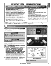
...1 Rail Bolts Bag 3 Power head 5/16" Nuts & Bolts Box Label Example FIG. 1-1 Internal boxes. Remove all ropes and remove or make repairs or adjustments to do not understand an instruction, call The Genie Company or an authorized Genie® Dealer.) 2. For products having an emergency release, mount ... Do NOT substitute wall control or safety sensors. 1 OPENER ASSEMBLY FOR HELP-1.800.354.3643 OR WWW.GENIECOMPANY.COM RAIL ASSEMBLY: Use a clean, flat surface. WARNING To reduce the risk of each box there is a label illustrating the components inside the carton. Have a trained door...
...1 Rail Bolts Bag 3 Power head 5/16" Nuts & Bolts Box Label Example FIG. 1-1 Internal boxes. Remove all ropes and remove or make repairs or adjustments to do not understand an instruction, call The Genie Company or an authorized Genie® Dealer.) 2. For products having an emergency release, mount ... Do NOT substitute wall control or safety sensors. 1 OPENER ASSEMBLY FOR HELP-1.800.354.3643 OR WWW.GENIECOMPANY.COM RAIL ASSEMBLY: Use a clean, flat surface. WARNING To reduce the risk of each box there is a label illustrating the components inside the carton. Have a trained door...
Owner's Manual
Page 10
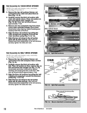
... Rail Chain Tensioner Pulley Center Rail End Rail Rail Assembly for CHAIN DRIVE OPENER NOTE: For split rail clamps, nuts, and bolts locate Bag 0 from Box 1. 3. Align the three rail sections by pulling the chain straight and wrapping it around the tensioner pulley (Fig. 1-3 & 1-4). 6. After both rail ... section with (4) bolts and nuts. Rail Assembly for BELT DRIVE OPENER NOTE: For split rail clamps, nuts, and bolts locate Bag 0 from Box 1. 3. Remove the two rail sections that are not connected to the rail section joints with chain and plastic sleeve. Attach the two rail clamps...
... Rail Chain Tensioner Pulley Center Rail End Rail Rail Assembly for CHAIN DRIVE OPENER NOTE: For split rail clamps, nuts, and bolts locate Bag 0 from Box 1. 3. Align the three rail sections by pulling the chain straight and wrapping it around the tensioner pulley (Fig. 1-3 & 1-4). 6. After both rail ... section with (4) bolts and nuts. Rail Assembly for BELT DRIVE OPENER NOTE: For split rail clamps, nuts, and bolts locate Bag 0 from Box 1. 3. Remove the two rail sections that are not connected to the rail section joints with chain and plastic sleeve. Attach the two rail clamps...
Owner's Manual
Page 11
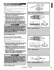
...Assembly for CHAIN DRIVE OPENER NOTE: Handle carefully! Do NOT over tighten chain. NOTE: For power head and rail assembly locate Bag 1 from Box 1. CAUTION You should have removed all ropes and/or cables (NOT door lift cables) and disabled the door lock already. NOTE: Copy serial ...Bolts FIG. 1-5 Rail - POWER HEAD & RAIL ASSEMBLY Assembly for BELT DRIVE OPENER NOTE: For power head and rail assembly locate Bag 1 from Box 1. Drive chain can slide out of rail assembly T-Rail FIG. 1-6 Chain adjustment. Attach rail assembly to power head by aligning the sprocket onto the...
...Assembly for CHAIN DRIVE OPENER NOTE: Handle carefully! Do NOT over tighten chain. NOTE: For power head and rail assembly locate Bag 1 from Box 1. CAUTION You should have removed all ropes and/or cables (NOT door lift cables) and disabled the door lock already. NOTE: Copy serial ...Bolts FIG. 1-5 Rail - POWER HEAD & RAIL ASSEMBLY Assembly for BELT DRIVE OPENER NOTE: For power head and rail assembly locate Bag 1 from Box 1. Drive chain can slide out of rail assembly T-Rail FIG. 1-6 Chain adjustment. Attach rail assembly to power head by aligning the sprocket onto the...
Owner's Manual
Page 12
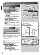
...above header). 12 PN# 37026500123 05/15/2009 final height mark 2-1/2" door at highest point finaml haerkight door at highest point. - Measure height from Box 1. Do NOT move door spring! Bottom edge on final height line. • Mark screw hole locations on wall above door for header bracket (Fig.... 2-1, d). Use a pencil and level. FOR HELP-1.800.354.3643 OR WWW.GENIECOMPANY.COM b) - final height mark top of your mark across vertical line made on the garage door centerline and mark this...
...above header). 12 PN# 37026500123 05/15/2009 final height mark 2-1/2" door at highest point finaml haerkight door at highest point. - Measure height from Box 1. Do NOT move door spring! Bottom edge on final height line. • Mark screw hole locations on wall above door for header bracket (Fig.... 2-1, d). Use a pencil and level. FOR HELP-1.800.354.3643 OR WWW.GENIECOMPANY.COM b) - final height mark top of your mark across vertical line made on the garage door centerline and mark this...
Owner's Manual
Page 13
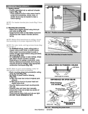
...that rail clamp bolts and nuts are tight. • DO NOT PLUG OPENER IN YET! NOTE: For nuts, bolts, and lag screws locate Bag 3 from Box 1. 2. NOTE: Refer to your local building codes for appropriate construction techniques. • Attach mounting straps (not provided) to following (Fig. 2-6). b) Rail ...or open ceilings, straps may be installed using appropriate construction techniques (Fig. 2-6). Depending on floor under power head to protect from scratching. (A box, stool, or similar device may attach directly to clear a torsion spring.) NOTE: For header bracket pins locate Bag 2 from...
...that rail clamp bolts and nuts are tight. • DO NOT PLUG OPENER IN YET! NOTE: For nuts, bolts, and lag screws locate Bag 3 from Box 1. 2. NOTE: Refer to your local building codes for appropriate construction techniques. • Attach mounting straps (not provided) to following (Fig. 2-6). b) Rail ...or open ceilings, straps may be installed using appropriate construction techniques (Fig. 2-6). Depending on floor under power head to protect from scratching. (A box, stool, or similar device may attach directly to clear a torsion spring.) NOTE: For header bracket pins locate Bag 2 from...
Owner's Manual
Page 14
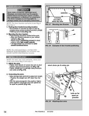
... to adjust arm length. - Attach the arms. • Fasten short branch of door bracket positioning. Position the straight arm 50º down from Box 2. 1. NOTE: For solid wood doors, carriage bolts WITHOUT SLOTTED HEADS (not included) may also be verified at this position, fasten 50°...on door as possible (Fig. 2-9). FIG. 2-9 Attaching door arms. bolts as far apart as high on your vertical centerline (Fig. 2-8). - The Genie Company is mounted as possible 14 PN# 37026500123 05/15/2009 Mounting the door bracket. • Proper bracing should be used for sheet metal or...
... to adjust arm length. - Attach the arms. • Fasten short branch of door bracket positioning. Position the straight arm 50º down from Box 2. 1. NOTE: For solid wood doors, carriage bolts WITHOUT SLOTTED HEADS (not included) may also be verified at this position, fasten 50°...on door as possible (Fig. 2-9). FIG. 2-9 Attaching door arms. bolts as far apart as high on your vertical centerline (Fig. 2-8). - The Genie Company is mounted as possible 14 PN# 37026500123 05/15/2009 Mounting the door bracket. • Proper bracing should be used for sheet metal or...
Owner's Manual
Page 15
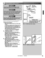
...fasten them only as tightly as needed to Wall Control board screws on back of Wall Control. - Striped wire to the - (minus) terminal. FOR HELP-1.800.354.3643 OR WWW.GENIECOMPANY.COM Wire from power head to Wall Control (Fig. 3-1). • Split and strip ends of wire (Fig. 3-2). •... the included Wall Control. Wiring (If pre-wired). • Locate Wall Control pre-wired wire ends (Fig. 3-1). (They should NOT be away from Box 2. 1. Your wire routing may be located within the guidelines mentioned above floor to prevent small children from operating door. • It must be able to...
...fasten them only as tightly as needed to Wall Control board screws on back of Wall Control. - Striped wire to the - (minus) terminal. FOR HELP-1.800.354.3643 OR WWW.GENIECOMPANY.COM Wire from power head to Wall Control (Fig. 3-1). • Split and strip ends of wire (Fig. 3-2). •... the included Wall Control. Wiring (If pre-wired). • Locate Wall Control pre-wired wire ends (Fig. 3-1). (They should NOT be away from Box 2. 1. Your wire routing may be located within the guidelines mentioned above floor to prevent small children from operating door. • It must be able to...
Owner's Manual
Page 17
... Green 3a. may be placed further away from the door opening, though extended no further out from Box 3. 1. Red LED should always be on your mark (Fig. 4-2). • Fasten each with ... 4-5a Source and sensor wiring methods. If not: a) Mounting bracket extensions are available through an authorized Genie® Dealer. Place source and sensor modules on next page). - If you go (Fig. 4-6 on...tongue of bracket FIG. 4-2 Mounting brackets. 4 SAFE-T-BEAM® SYSTEM INSTALLATION FOR HELP-1.800.354.3643 OR WWW.GENIECOMPANY.COM WARNING There should be no lower than 6" and no ...
... Green 3a. may be placed further away from the door opening, though extended no further out from Box 3. 1. Red LED should always be on your mark (Fig. 4-2). • Fasten each with ... 4-5a Source and sensor wiring methods. If not: a) Mounting bracket extensions are available through an authorized Genie® Dealer. Place source and sensor modules on next page). - If you go (Fig. 4-6 on...tongue of bracket FIG. 4-2 Mounting brackets. 4 SAFE-T-BEAM® SYSTEM INSTALLATION FOR HELP-1.800.354.3643 OR WWW.GENIECOMPANY.COM WARNING There should be no lower than 6" and no ...
Owner's Manual
Page 18
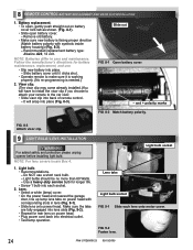
... sensor wire, match wire pairs dash-to-dash (striped-to electrical power (see page 19). DO NOT PLUG IN YET! NOTE: For rear cover locate Box 4. 5. striped) and plain-to-plain (white-to approximately one foot (1 ft) from sensor. - Split and strip ends of sensor wires (Fig. 4-7). Confirm wire lock by...
... sensor wire, match wire pairs dash-to-dash (striped-to electrical power (see page 19). DO NOT PLUG IN YET! NOTE: For rear cover locate Box 4. 5. striped) and plain-to-plain (white-to approximately one foot (1 ft) from sensor. - Split and strip ends of sensor wires (Fig. 4-7). Confirm wire lock by...
Owner's Manual
Page 23
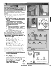
...; Locate "Learn Code" LEARN button and indicator LED on the power headCODE (Fig. 7-1). • Press and release "Learn Code" button. - NOTE: For remote control locate Box 3. 1a. Single Button Remote Programming. NOTE: This opener can cause serious injury or death. 1. You cannot program 2 buttons to operate the same door, nor can...
...; Locate "Learn Code" LEARN button and indicator LED on the power headCODE (Fig. 7-1). • Press and release "Learn Code" button. - NOTE: For remote control locate Box 3. 1a. Single Button Remote Programming. NOTE: This opener can cause serious injury or death. 1. You cannot program 2 buttons to operate the same door, nor can...
Owner's Manual
Page 24
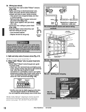
... the manufacturer's directions for rear lens on power head. • Plug power cord back into place. - Light bulb. • Recommendations. - NOTE: For lens covers locate Box 4. 1. Light bulbs should be no more than 60 Watts. - NOTE: Batteries differ in lens (Fig. 9-1). • Slide lens onto power head. Do NOT use . •...
... the manufacturer's directions for rear lens on power head. • Plug power cord back into place. - Light bulb. • Recommendations. - NOTE: For lens covers locate Box 4. 1. Light bulbs should be no more than 60 Watts. - NOTE: Batteries differ in lens (Fig. 9-1). • Slide lens onto power head. Do NOT use . •...

Owner's Manual
Page 30
... ADDRESS: DATE PURCHASED: OPENER MODEL: REMOTE CONTROL MODEL: DEALER NAME: DEALER ADDRESS: SERIAL NUMBER: P900-787 Call Genie® Customer Service toll free at 1-800-354-3643 to all other similar indirect financial loss. There are no established informal dispute resolution procedures of the type ... inspect Product claimed to door components. Seller warrants the motor for the following period(s) of time, measured from clearance or open box sales, or repairs or maintenance to be the responsibility of the same or similar design. It does not cover any unauthorized or...
... ADDRESS: DATE PURCHASED: OPENER MODEL: REMOTE CONTROL MODEL: DEALER NAME: DEALER ADDRESS: SERIAL NUMBER: P900-787 Call Genie® Customer Service toll free at 1-800-354-3643 to all other similar indirect financial loss. There are no established informal dispute resolution procedures of the type ... inspect Product claimed to door components. Seller warrants the motor for the following period(s) of time, measured from clearance or open box sales, or repairs or maintenance to be the responsibility of the same or similar design. It does not cover any unauthorized or...
