
Owner's Manual
Page 1
... Answers and Assistance: 1.800.354.3643 or visit www.geniecompany.com SAVE THIS MANUAL FOR FUTURE REFERENCE Homelink® is a registered trademark of Johnson Controls Technology Company. Installer: Leave this manual with sectional doors. d/b/a The Genie Company PN# 37026500123, 5/15/2009 ALWAYS AT YOUR COMMAND Models 2022/2024/2042 GARAGE DOOR OPENERS Includes: 2-Bulb Light System Wall Console Includes INTELLICODE® Remote Control Safe-T-Beam® System must be installed to close door.
... Answers and Assistance: 1.800.354.3643 or visit www.geniecompany.com SAVE THIS MANUAL FOR FUTURE REFERENCE Homelink® is a registered trademark of Johnson Controls Technology Company. Installer: Leave this manual with sectional doors. d/b/a The Genie Company PN# 37026500123, 5/15/2009 ALWAYS AT YOUR COMMAND Models 2022/2024/2042 GARAGE DOOR OPENERS Includes: 2-Bulb Light System Wall Console Includes INTELLICODE® Remote Control Safe-T-Beam® System must be installed to close door.
Owner's Manual
Page 2
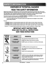
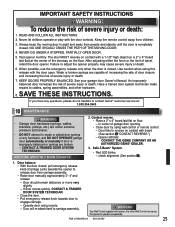
... door spring parts are fastened, such as, wood blocks, steel brackets, cables or other like items. Installations, repairs and adjustments must be done by a trained door system technician using proper tools and instructions. ELECTRICAL SHOCK HIGH SPRING TENSION 2 WARNING: CoourldSererisouultsinInDjueryath Turn OFF power before removing operator cover. SAFETY INFORMATION OVERVIEW OF POTENTIAL HAZARDS READ THIS SAFETY INFORMATION Garage doors are large, heavy objects that has a broken spring. Since moving objects, springs under high tension and electric motors...
... door spring parts are fastened, such as, wood blocks, steel brackets, cables or other like items. Installations, repairs and adjustments must be done by a trained door system technician using proper tools and instructions. ELECTRICAL SHOCK HIGH SPRING TENSION 2 WARNING: CoourldSererisouultsinInDjueryath Turn OFF power before removing operator cover. SAFETY INFORMATION OVERVIEW OF POTENTIAL HAZARDS READ THIS SAFETY INFORMATION Garage doors are large, heavy objects that has a broken spring. Since moving objects, springs under high tension and electric motors...
Owner's Manual
Page 3
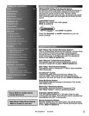
.... Lighted Wall Control* Operates door opener from inside garage. (Refer to each time the remote control is activated and automatically turns OFF 3 minutes later. Puts an invisible beam across the door opening and closing of the door opener by continuously changing the access code each new code only once. Automatically stops and reverses a closing door if the Safe-T-Beam® System** notes an operational problem. Features adjustable open and close the door. (Refer to close completely within 2 seconds of light for safer evening exits and entries. Watch...
.... Lighted Wall Control* Operates door opener from inside garage. (Refer to each time the remote control is activated and automatically turns OFF 3 minutes later. Puts an invisible beam across the door opening and closing of the door opener by continuously changing the access code each new code only once. Automatically stops and reverses a closing door if the Safe-T-Beam® System** notes an operational problem. Features adjustable open and close the door. (Refer to close completely within 2 seconds of light for safer evening exits and entries. Watch...
Owner's Manual
Page 4
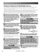
... glass panels? PRE-INSTALLATION CHECK LIST FOR HELP-1.800.354.3643 OR WWW.GENIECOMPANY.COM Things to consider if you are planning to see if the mounting location for the Safe-T-Beam® System is clear from the power head once it is improperly balanced or has a broken spring, have a separate entry door, you should consider an emergency release kit (GER-2) for use with your new door opener kit). (Refer...
... glass panels? PRE-INSTALLATION CHECK LIST FOR HELP-1.800.354.3643 OR WWW.GENIECOMPANY.COM Things to consider if you are planning to see if the mounting location for the Safe-T-Beam® System is clear from the power head once it is improperly balanced or has a broken spring, have a separate entry door, you should consider an emergency release kit (GER-2) for use with your new door opener kit). (Refer...
Owner's Manual
Page 6
... walk or run under automatic garage door. Place next to wall control. ©1999 Entrapment Warning Label Safe-T-Beam® Source with wire (Red LED) Safe-T-Beam® Sensor with chain or belt attached) and place on floor. Enlever les boîtes internes. Remove rail sections not connected to reverse door, repair or replace opener. Quite las secciones de riel no conectadas a la cadena o correa. Follow instructions in line and pull plastic...
... walk or run under automatic garage door. Place next to wall control. ©1999 Entrapment Warning Label Safe-T-Beam® Source with wire (Red LED) Safe-T-Beam® Sensor with chain or belt attached) and place on floor. Enlever les boîtes internes. Remove rail sections not connected to reverse door, repair or replace opener. Quite las secciones de riel no conectadas a la cadena o correa. Follow instructions in line and pull plastic...
Owner's Manual
Page 9
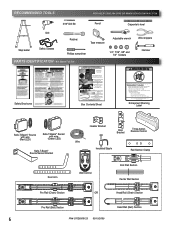
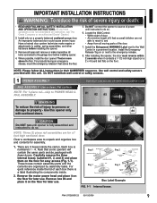
... property - Remove all locks connected to the garage door before installing the opener. 3. Use wall control and safety sensors provided with fewer boxes. Use this unit. CAUTION Do NOT run until instructed to do so. Each box is fully assembled and instructed to do not understand an instruction, call The Genie Company or an authorized Genie® Dealer.) 2. Bag 0 Rail Connectors Rail Connector Bolts Rail Connector Nuts Bag 2 Header Bracket Bolts Bag 1 Rail Bolts Bag 3 Power head 5/16...
... property - Remove all locks connected to the garage door before installing the opener. 3. Use wall control and safety sensors provided with fewer boxes. Use this unit. CAUTION Do NOT run until instructed to do so. Each box is fully assembled and instructed to do not understand an instruction, call The Genie Company or an authorized Genie® Dealer.) 2. Bag 0 Rail Connectors Rail Connector Bolts Rail Connector Nuts Bag 2 Header Bracket Bolts Bag 1 Rail Bolts Bag 3 Power head 5/16...
Owner's Manual
Page 11
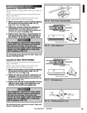
... chain. Chain Pulley Bracket (at wall end of rail) Use 1/2" socket on adjustment nut Tighten nut to power head by aligning the sprocket onto the motor shaft. PN# 37026500123 05/15/2009 11 Use (3) bolts, 5/16 -18 x 1/2" (Fig. 1-5). 2. Tighten the chain by turning the adjustment nut clockwise. Begin with Section 2 INSTALLATION. Use (3) bolts, 5/16 -18 x 1/2" (Fig. 1-5). 2. Set assembled power head and rail aside. POWER HEAD & RAIL ASSEMBLY Assembly for BELT DRIVE OPENER NOTE: For power head and rail assembly locate Bag 1 from power...
... chain. Chain Pulley Bracket (at wall end of rail) Use 1/2" socket on adjustment nut Tighten nut to power head by aligning the sprocket onto the motor shaft. PN# 37026500123 05/15/2009 11 Use (3) bolts, 5/16 -18 x 1/2" (Fig. 1-5). 2. Tighten the chain by turning the adjustment nut clockwise. Begin with Section 2 INSTALLATION. Use (3) bolts, 5/16 -18 x 1/2" (Fig. 1-5). 2. Set assembled power head and rail aside. POWER HEAD & RAIL ASSEMBLY Assembly for BELT DRIVE OPENER NOTE: For power head and rail assembly locate Bag 1 from power...
Owner's Manual
Page 13
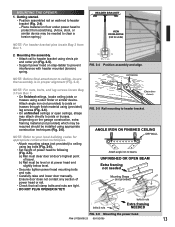
... pin and cotter pin (Fig. 2-5). • Support power head on wall next to ceiling using (provided) lag screws (Fig. 2-6). • On unfinished ceilings or open ceilings, straps may be level or at door's highest point of travel. NOTE: For nuts, bolts, and lag screws locate Bag 3 from Box 1. 2. Attach angle iron (not provided) to header bracket using a stud finder or similar device. a) Rail must be needed Mounting...
... pin and cotter pin (Fig. 2-5). • Support power head on wall next to ceiling using (provided) lag screws (Fig. 2-6). • On unfinished ceilings or open ceilings, straps may be level or at door's highest point of travel. NOTE: For nuts, bolts, and lag screws locate Bag 3 from Box 1. 2. Attach angle iron (not provided) to header bracket using a stud finder or similar device. a) Rail must be needed Mounting...
Owner's Manual
Page 15
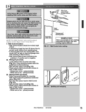
...-wired. Cut or pinched wires can cause the door to operate unexpectedly and the light not to the opener before installing Wall Control wires and Wall Control. PN# 37026500123 05/15/2009 15 CAUTION Staples which are polarized, (+) positive and (-) negative. 2a. This is NO power to work. Striped wire to reach the garage door while standing at Wall Control.) • Wall Control board screw connections are too tight can cut or pinch wires. Wall Control location. • Wall Control location...
...-wired. Cut or pinched wires can cause the door to operate unexpectedly and the light not to the opener before installing Wall Control wires and Wall Control. PN# 37026500123 05/15/2009 15 CAUTION Staples which are polarized, (+) positive and (-) negative. 2a. This is NO power to work. Striped wire to reach the garage door while standing at Wall Control.) • Wall Control board screw connections are too tight can cut or pinch wires. Wall Control location. • Wall Control location...
Owner's Manual
Page 16
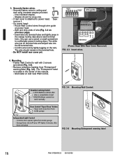
... wall near Wall Control. Mounting. • Fasten Wall Control to work normally Door Control "Open/Close" Button - Locking Clips Terminal Holes 6 54 321 wire guide 6 54 3 21 +- Use insulated staples. - Insert wire into the #2 terminal hole. - The "Entrapment" label is located in locking clips.) The white wire into #1 terminal hole and striped wire into terminal holes and lightly press in the terminal hole. • Do NOT install rear cover yet. Energy-Saver shut-off turns OFF lights...
... wall near Wall Control. Mounting. • Fasten Wall Control to work normally Door Control "Open/Close" Button - Locking Clips Terminal Holes 6 54 321 wire guide 6 54 3 21 +- Use insulated staples. - Insert wire into the #2 terminal hole. - The "Entrapment" label is located in locking clips.) The white wire into #1 terminal hole and striped wire into terminal holes and lightly press in the terminal hole. • Do NOT install rear cover yet. Energy-Saver shut-off turns OFF lights...
Owner's Manual
Page 17
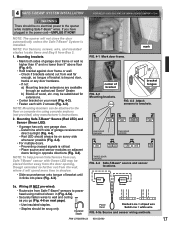
... close the door automatically unless the Safe-T-Beam® System is installed. NOTE: For Sensors, screws, wire, and insulated staples locate items and Bag 8 from wall far enough, so tongue of bracket until it clicks into place (Fig. 4-3). Red LED should always be on next page). - Insulated Staple Source Sensor 6 5 4 3 2 1 or 6 5 4 3 2 1 Power Head Dashed Line = striped wire Solid Line = white wire FIG. 4-5a Source and sensor wiring methods. Red Green 3a. Mounting brackets...
... close the door automatically unless the Safe-T-Beam® System is installed. NOTE: For Sensors, screws, wire, and insulated staples locate items and Bag 8 from wall far enough, so tongue of bracket until it clicks into place (Fig. 4-3). Red LED should always be on next page). - Insulated Staple Source Sensor 6 5 4 3 2 1 or 6 5 4 3 2 1 Power Head Dashed Line = striped wire Solid Line = white wire FIG. 4-5a Source and sensor wiring methods. Red Green 3a. Mounting brackets...
Owner's Manual
Page 19
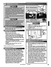
... the adjustment screws on both sensors. Use the adjustment screw located on motor must be properly grounded in any way. When the LED units are aligned the Red LED will only fit a grounded type outlet. CAUTION • Do NOT use an extension cord. • Do NOT use alternate power supplies. 6" 5" max min from from circuit. • Remove rear cover and motor cover. - The LED indicator light on the Wall Control during the closing , if Safe-T-Beam® is opening...
... the adjustment screws on both sensors. Use the adjustment screw located on motor must be properly grounded in any way. When the LED units are aligned the Red LED will only fit a grounded type outlet. CAUTION • Do NOT use an extension cord. • Do NOT use alternate power supplies. 6" 5" max min from from circuit. • Remove rear cover and motor cover. - The LED indicator light on the Wall Control during the closing , if Safe-T-Beam® is opening...
Owner's Manual
Page 20
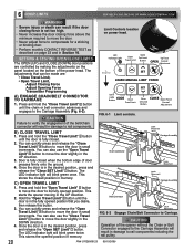
... rail components. LED Indicator Light Open Open Set Limit Travel Limit Button Up Force OPEN Control Adjustment To Garage Door SET LEARN MANUAL LIMIT FORCE SET A) ENGAGE CHAIN/BELT CONNECTOR TO CARRIAGE 1. Door is in small increments. The LED indicator light will blink green twice. Press and hold the "Close Travel Limit" button until the chain or belt connector advances and engages to move the door in the fully opened position that you desire, then release this direction Latch Movement Latch Movement Carriage Assembly 1. You can also use the "Close Travel Limit" button...
... rail components. LED Indicator Light Open Open Set Limit Travel Limit Button Up Force OPEN Control Adjustment To Garage Door SET LEARN MANUAL LIMIT FORCE SET A) ENGAGE CHAIN/BELT CONNECTOR TO CARRIAGE 1. Door is in small increments. The LED indicator light will blink green twice. Press and hold the "Close Travel Limit" button until the chain or belt connector advances and engages to move the door in the fully opened position that you desire, then release this direction Latch Movement Latch Movement Carriage Assembly 1. You can also use the "Close Travel Limit" button...
Owner's Manual
Page 22
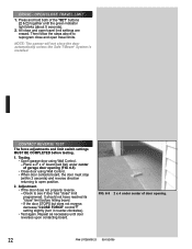
... door has "close" limit programmed. FIG. 6-5 2 x 4 under center of door opening (FIG. 6-5). • Close door using Wall Control. - Testing. • Open garage door using Wall Control. • When door contacts board, the door must stop (within 2 seconds) and reverse direction returning to open position. 2. If the door STOPS but does not reverse, decrease "CLOSE FORCE" control CLOSE setting slightly (turn it counter-clockwise). • Test again. Repeat as necessary until the green indicator light blinks (about 5 seconds). 2. Check to reprogram close and open travel...
... door has "close" limit programmed. FIG. 6-5 2 x 4 under center of door opening (FIG. 6-5). • Close door using Wall Control. - Testing. • Open garage door using Wall Control. • When door contacts board, the door must stop (within 2 seconds) and reverse direction returning to open position. 2. If the door STOPS but does not reverse, decrease "CLOSE FORCE" control CLOSE setting slightly (turn it counter-clockwise). • Test again. Repeat as necessary until the green indicator light blinks (about 5 seconds). 2. Check to reprogram close and open travel...
Owner's Manual
Page 23
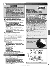
... Light Open Open Set Limit Travel Limit Button Up Force OPEN Control Adjustment NOTE: The door will erase programmed memory and limits must be determined by pulling the Emergency Release. NOTE: Pushing two buttons on a multi-button remote is connected. • Consult your car owner's manual. Keep people moving door can program a maximum of twice per second. • Within 30 seconds, push remote control button once. - FCC and IC CERTIFIED This device complies with the instructions, may be reset. • For each button separately using...
... Light Open Open Set Limit Travel Limit Button Up Force OPEN Control Adjustment NOTE: The door will erase programmed memory and limits must be determined by pulling the Emergency Release. NOTE: Pushing two buttons on a multi-button remote is connected. • Consult your car owner's manual. Keep people moving door can program a maximum of twice per second. • Within 30 seconds, push remote control button once. - FCC and IC CERTIFIED This device complies with the instructions, may be reset. • For each button separately using...
Owner's Manual
Page 24
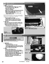
... for longer life. • Screw 1 bulb into electrical outlet. • Test lamp operation. Use a heavy duty service bulb for rear lens on battery cover lock tab as shown. (Fig. 8-1). • Slide open battery cover. - Light bulb. • Recommendations. - FIG. 9-2 Fasten lens. 24 PN# 37026500123 05/15/2009 Battery replacement. • To open, gently push straight out on power head. • Plug power cord back into each lens onto motor cover. Recommended replacement battery type: Alkaline A23, 12...
... for longer life. • Screw 1 bulb into electrical outlet. • Test lamp operation. Use a heavy duty service bulb for rear lens on battery cover lock tab as shown. (Fig. 8-1). • Slide open battery cover. - Light bulb. • Recommendations. - FIG. 9-2 Fasten lens. 24 PN# 37026500123 05/15/2009 Battery replacement. • To open, gently push straight out on power head. • Plug power cord back into each lens onto motor cover. Recommended replacement battery type: Alkaline A23, 12...
Owner's Manual
Page 25
... DOOR. 4. After adjusting either the force or the limit of garage door opening. • Close door by using wall control or remote control. - When possible, use the emergency release only when the door is completely closed , pull emergency release knob (Carriage Lock) towards door to reverse on contact with board (See section 6 "CONTACT REVERSE.") - If door moves quickly, CONTACT A TRAINED DOOR SYSTEM TECHNICIAN. • Close the door. • Pull emergency release knob towards the opener to release door from children. 3. Any other hardware. 8. Never let children operate...
... DOOR. 4. After adjusting either the force or the limit of garage door opening. • Close door by using wall control or remote control. - When possible, use the emergency release only when the door is completely closed , pull emergency release knob (Carriage Lock) towards door to reverse on contact with board (See section 6 "CONTACT REVERSE.") - If door moves quickly, CONTACT A TRAINED DOOR SYSTEM TECHNICIAN. • Close the door. • Pull emergency release knob towards the opener to release door from children. 3. Any other hardware. 8. Never let children operate...
Owner's Manual
Page 27
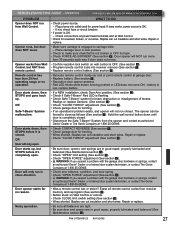
... garage door. • Replace battery (See section 8 ). • Reposition door opener antenna. • Red LED blinks while button is closed . • Disconnect the Safe-T-Beam® System from remote control. Noisy operation. • Be sure all remote control codes from Wall Control. If not, check fuse or circuit breaker. • If power is OK. - Place carriage lever in close as follows (See section 5 ). OR Safe-T-Beam® System malfunction. Door will NOT run in lock position. • Check to make sure chain/belt...
... garage door. • Replace battery (See section 8 ). • Reposition door opener antenna. • Red LED blinks while button is closed . • Disconnect the Safe-T-Beam® System from remote control. Noisy operation. • Be sure all remote control codes from Wall Control. If not, check fuse or circuit breaker. • If power is OK. - Place carriage lever in close as follows (See section 5 ). OR Safe-T-Beam® System malfunction. Door will NOT run in lock position. • Check to make sure chain/belt...
Owner's Manual
Page 28
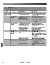
...head LED Red LED showing Green LED showing OFF OFF Continuous ON 1 BLINK, Pause (Repeat) 1 BLINK, Pause (Repeat) Possible Problem Solution Normal operation • Programming incomplete • Transmitter has not learned • Limit Programming incomplete • Safe-T-Beam® sensor obstruction going down • Door obstruction going down • Door obstruction going up None required • Complete programming • Push transmitter button to power head or wire connection at 1-800-35-GENIE • Reverse wire placement in power head connector. • Chain/belt...
...head LED Red LED showing Green LED showing OFF OFF Continuous ON 1 BLINK, Pause (Repeat) 1 BLINK, Pause (Repeat) Possible Problem Solution Normal operation • Programming incomplete • Transmitter has not learned • Limit Programming incomplete • Safe-T-Beam® sensor obstruction going down • Door obstruction going down • Door obstruction going up None required • Complete programming • Push transmitter button to power head or wire connection at 1-800-35-GENIE • Reverse wire placement in power head connector. • Chain/belt...

Owner's Manual
Page 30
... to , loss of use new or reconditioned parts, or a new or reconditioned Product of the purchaser. Purchaser must contact Genie® customer service and provide proof of the date and location of the type described in commercial or industrial building applications. PURCHASER: INSTALLATION ADDRESS: DATE PURCHASED: OPENER MODEL: REMOTE CONTROL MODEL: DEALER NAME: DEALER ADDRESS: SERIAL NUMBER: P900-787 Models 2022/2024/2042 Limited Warranty GMI Holdings, Inc...
... to , loss of use new or reconditioned parts, or a new or reconditioned Product of the purchaser. Purchaser must contact Genie® customer service and provide proof of the date and location of the type described in commercial or industrial building applications. PURCHASER: INSTALLATION ADDRESS: DATE PURCHASED: OPENER MODEL: REMOTE CONTROL MODEL: DEALER NAME: DEALER ADDRESS: SERIAL NUMBER: P900-787 Models 2022/2024/2042 Limited Warranty GMI Holdings, Inc...


