
Owner's Manual
Page 6
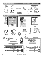
...en plastique pour le dégager de la chaîne ou cravate en plastique outre de courroie. RECOMMENDED TOOLS FOR HELP-1.800.354.3643 OR WWW.GENIECOMPANY.COM 3/16" Drill Bit Pencil Carpenter's level Drill Step ladder Safety Glasses Ratchet Tape measure Phillips screwdriver... or plastic tie off belt. Procéder selon les instructions stipumléoenstadgaenàs sleuimvraen.uel d'installation pour les étapes de Box Contents Sheet Adjustable wrench Wire strippers 1/4", 7/16", 3/8" and 1/2" Sockets Hammer Child can result. • Never let child walk or run...
...en plastique pour le dégager de la chaîne ou cravate en plastique outre de courroie. RECOMMENDED TOOLS FOR HELP-1.800.354.3643 OR WWW.GENIECOMPANY.COM 3/16" Drill Bit Pencil Carpenter's level Drill Step ladder Safety Glasses Ratchet Tape measure Phillips screwdriver... or plastic tie off belt. Procéder selon les instructions stipumléoenstadgaenàs sleuimvraen.uel d'installation pour les étapes de Box Contents Sheet Adjustable wrench Wire strippers 1/4", 7/16", 3/8" and 1/2" Sockets Hammer Child can result. • Never let child walk or run...
Owner's Manual
Page 9
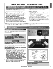
... Srews PN# 37026500123 05/15/2009 9 Use wall control and safety sensors provided with fewer boxes. Do NOT substitute wall control or safety sensors. 1 OPENER ASSEMBLY FOR HELP-1.800.354.3643 OR WWW.GENIECOMPANY.COM RAIL ASSEMBLY: Use a clean, flat surface. WARNING To reduce... Example FIG. 1-1 Internal boxes. Remove box #4 and place it on or next to do so. NOTE: For 1-piece rail-skip to do not understand an instruction, call The Genie Company or an authorized Genie® Dealer.) 2. Install the Entrapment WARNING Label next to reach it contacts a 1-1/2 inch high object (...
... Srews PN# 37026500123 05/15/2009 9 Use wall control and safety sensors provided with fewer boxes. Do NOT substitute wall control or safety sensors. 1 OPENER ASSEMBLY FOR HELP-1.800.354.3643 OR WWW.GENIECOMPANY.COM RAIL ASSEMBLY: Use a clean, flat surface. WARNING To reduce... Example FIG. 1-1 Internal boxes. Remove box #4 and place it on or next to do so. NOTE: For 1-piece rail-skip to do not understand an instruction, call The Genie Company or an authorized Genie® Dealer.) 2. Install the Entrapment WARNING Label next to reach it contacts a 1-1/2 inch high object (...
Owner's Manual
Page 10
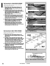
...Rail Rail Assembly for CHAIN DRIVE OPENER NOTE: For split rail clamps, nuts, and bolts locate Bag 0 from Box 1. 3. Carefully remove the third rail section with chain Rail Clamp Bolts End Rail HIGH SPRING TENSION RseCerpvaainciresCpoerarausdosjnuesutSsmineegrniptosroumpsuesrItntbojeoulmsryaandoderibnDystaerutarcattiihnoends dSmbooraomainnrceNusdintfdiraOsguotc.... for BELT DRIVE OPENER NOTE: For split rail clamps, nuts, and bolts locate Bag 0 from Box 1. 3. Remove the two rail sections that are not connected to the rail sections, securely tighten the bolts and nuts.
...Rail Rail Assembly for CHAIN DRIVE OPENER NOTE: For split rail clamps, nuts, and bolts locate Bag 0 from Box 1. 3. Carefully remove the third rail section with chain Rail Clamp Bolts End Rail HIGH SPRING TENSION RseCerpvaainciresCpoerarausdosjnuesutSsmineegrniptosroumpsuesrItntbojeoulmsryaandoderibnDystaerutarcattiihnoends dSmbooraomainnrceNusdintfdiraOsguotc.... for BELT DRIVE OPENER NOTE: For split rail clamps, nuts, and bolts locate Bag 0 from Box 1. 3. Remove the two rail sections that are not connected to the rail sections, securely tighten the bolts and nuts.
Owner's Manual
Page 11
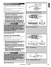
NOTE: For power head and rail assembly locate Bag 1 from Box 1. Tighten the chain by turning the adjustment nut clockwise. Begin with Section 2 INSTALLATION. Use (3) bolts, 5/16 -18 x 1/2" (Fig. 1-5). 2. Do NOT over tighten chain. Use 5/16"-... assembled power head and rail aside. POWER HEAD & RAIL ASSEMBLY Assembly for BELT DRIVE OPENER NOTE: For power head and rail assembly locate Bag 1 from Box 1.
NOTE: For power head and rail assembly locate Bag 1 from Box 1. Tighten the chain by turning the adjustment nut clockwise. Begin with Section 2 INSTALLATION. Use (3) bolts, 5/16 -18 x 1/2" (Fig. 1-5). 2. Do NOT over tighten chain. Use 5/16"-... assembled power head and rail aside. POWER HEAD & RAIL ASSEMBLY Assembly for BELT DRIVE OPENER NOTE: For power head and rail assembly locate Bag 1 from Box 1.
Owner's Manual
Page 12
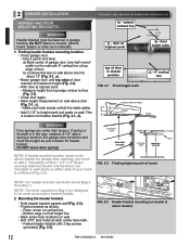
... a) Mark center of garage door (one-half overall width) on the wall with 2 lag screws (provided) (Fig. 2-3). Measure height from Box 1. door at top edge of your mark across vertical line made earlier. • Add 2-1/2" to floor (Fig. 2-2). • Close door... again. • Mark height measurement on wall above door for header bracket (Fig. 2-1, d). b) Continue this height as shown. - FOR HELP-1.800.354.3643 OR WWW.GENIECOMPANY.COM b) - a) - 6" vertical line 2-1/2" HIGHEST POINT OF TRAVEL HEADER TRACK WARNING Door springs are designed to drywall, ...
... a) Mark center of garage door (one-half overall width) on the wall with 2 lag screws (provided) (Fig. 2-3). Measure height from Box 1. door at top edge of your mark across vertical line made earlier. • Add 2-1/2" to floor (Fig. 2-2). • Close door... again. • Mark height measurement on wall above door for header bracket (Fig. 2-1, d). b) Continue this height as shown. - FOR HELP-1.800.354.3643 OR WWW.GENIECOMPANY.COM b) - a) - 6" vertical line 2-1/2" HIGHEST POINT OF TRAVEL HEADER TRACK WARNING Door springs are designed to drywall, ...
Owner's Manual
Page 13
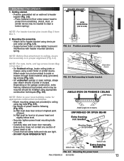
... head mounting bolts and nuts. • Carefully raise and lower door manually. NOTE: For nuts, bolts, and lag screws locate Bag 3 from Box 1. • On finished ceilings, locate ceiling joists or trusses using clevis pin and cotter pin (Fig. 2-5). • Support power head on floor... beams UNFINISHED OR OPEN BEAM Extra framing not needed to clear a torsion spring.) NOTE: For header bracket pins locate Bag 2 from scratching. (A box, stool, or similar device may attach directly to ceiling using (provided) lag screws (Fig. 2-6). • On unfinished ceilings or open ceilings, straps...
... head mounting bolts and nuts. • Carefully raise and lower door manually. NOTE: For nuts, bolts, and lag screws locate Bag 3 from Box 1. • On finished ceilings, locate ceiling joists or trusses using clevis pin and cotter pin (Fig. 2-5). • Support power head on floor... beams UNFINISHED OR OPEN BEAM Extra framing not needed to clear a torsion spring.) NOTE: For header bracket pins locate Bag 2 from scratching. (A box, stool, or similar device may attach directly to ceiling using (provided) lag screws (Fig. 2-6). • On unfinished ceilings or open ceilings, straps...
Owner's Manual
Page 14
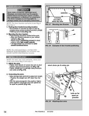
...(not provided) for a bracing kit. INSTALL DOOR ARMS NOTE: For door arm nuts and bolts, clevis and cotter pins locate Bag 5 from Box 2. 1. Finding door bracket mounting location. • Door bracket is not responsible for damage caused due to improperly braced door. centerline of top ...2-9 Attaching door arms. bolts as far apart as possible along vertical centerline and NO LOWER THAN top set of rollers (Fig. 2-7). 2. The Genie Company is mounted as high on your vertical centerline (Fig. 2-8). - DOOR BRACKET: CAUTION Doors made of masonite, lightweight wood, fiberglass, and ...
...(not provided) for a bracing kit. INSTALL DOOR ARMS NOTE: For door arm nuts and bolts, clevis and cotter pins locate Bag 5 from Box 2. 1. Finding door bracket mounting location. • Door bracket is not responsible for damage caused due to improperly braced door. centerline of top ...2-9 Attaching door arms. bolts as far apart as possible along vertical centerline and NO LOWER THAN top set of rollers (Fig. 2-7). 2. The Genie Company is mounted as high on your vertical centerline (Fig. 2-8). - DOOR BRACKET: CAUTION Doors made of masonite, lightweight wood, fiberglass, and ...
Owner's Manual
Page 15
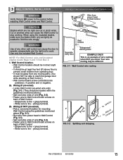
... Control location should be in direct sight of door. • It should be different. White wire to stop working. FOR HELP-1.800.354.3643 OR WWW.GENIECOMPANY.COM Wire from Box 2. 1. CAUTION Staples which are polarized, (+) positive and (-) negative. 2a. FIG. 3-1 Wall Control wire routing or White 2" - 1/2" + or BStlaricpked FIG. 3-2 Splitting and...
... Control location should be in direct sight of door. • It should be different. White wire to stop working. FOR HELP-1.800.354.3643 OR WWW.GENIECOMPANY.COM Wire from Box 2. 1. CAUTION Staples which are polarized, (+) positive and (-) negative. 2a. FIG. 3-1 Wall Control wire routing or White 2" - 1/2" + or BStlaricpked FIG. 3-2 Splitting and...
Owner's Manual
Page 17
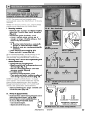
...to power head using concrete anchors (not provided) obey manufacturer's instructions. 2. If not: a) Mounting bracket extensions are available through an authorized Genie® Dealer. RLEEDD GRLEEDEN GRLEEDEN RLEEDD RLEEDD GRLEEDEN ONE DOOR GARAGE TWO DOOR GARAGE GRLEEDEN RLEEDD RLEEDD GRLEEDEN GREEN LED RED LED THREE DOOR... (Red LED) and Sensor (Green LED). • If garage has only one garage door. - Check if brackets extend out from Box 3. 1. 4 SAFE-T-BEAM® SYSTEM INSTALLATION FOR HELP-1.800.354.3643 OR WWW.GENIECOMPANY.COM WARNING There should be snug only.
...to power head using concrete anchors (not provided) obey manufacturer's instructions. 2. If not: a) Mounting bracket extensions are available through an authorized Genie® Dealer. RLEEDD GRLEEDEN GRLEEDEN RLEEDD RLEEDD GRLEEDEN ONE DOOR GARAGE TWO DOOR GARAGE GRLEEDEN RLEEDD RLEEDD GRLEEDEN GREEN LED RED LED THREE DOOR... (Red LED) and Sensor (Green LED). • If garage has only one garage door. - Check if brackets extend out from Box 3. 1. 4 SAFE-T-BEAM® SYSTEM INSTALLATION FOR HELP-1.800.354.3643 OR WWW.GENIECOMPANY.COM WARNING There should be snug only.
Owner's Manual
Page 18
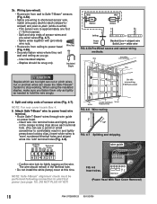
....) Insert white wires to power head wire terminal. • Route Safe-T-Beam® wires through wire guide on the wire. NOTE: For rear cover locate Box 4. 5. The wire should be performed following connection to hold the wire snugly. NOTE: Safe-T-Beam® alignment check must be snug only. PB Infared Sensor...
....) Insert white wires to power head wire terminal. • Route Safe-T-Beam® wires through wire guide on the wire. NOTE: For rear cover locate Box 4. 5. The wire should be performed following connection to hold the wire snugly. NOTE: Safe-T-Beam® alignment check must be snug only. PB Infared Sensor...
Owner's Manual
Page 23
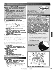
... and objects away from the missing remote control, or any other which may cause harmful interference to play with 1 door. NOTE: For remote control locate Box 3. 1a. NOTE: This opener can cause serious injury or death. 1. Indicator LED will move . • Press button again. - Indicator LED will erase programmed memory and...
... and objects away from the missing remote control, or any other which may cause harmful interference to play with 1 door. NOTE: For remote control locate Box 3. 1a. NOTE: This opener can cause serious injury or death. 1. Indicator LED will move . • Press button again. - Indicator LED will erase programmed memory and...
Owner's Manual
Page 24
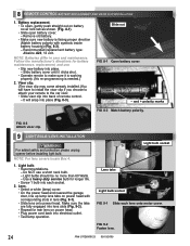
.... 8-3 Attach visor clip. 9 LIGHT BULB/LENS INSTALLATION WARNING For added safety and protection please unplug opener before installing light bulb. NOTE: For lens covers locate Box 4. 1. and + polarity marks FIG. 8-2 Match battery polarity. Light bulbs should be no more than 60 Watts. - 8 REMOTE CONTROL BATTERY REPLACEMENT AND VISOR CLIP INSTALLATION 1. Battery...
.... 8-3 Attach visor clip. 9 LIGHT BULB/LENS INSTALLATION WARNING For added safety and protection please unplug opener before installing light bulb. NOTE: For lens covers locate Box 4. 1. and + polarity marks FIG. 8-2 Match battery polarity. Light bulbs should be no more than 60 Watts. - 8 REMOTE CONTROL BATTERY REPLACEMENT AND VISOR CLIP INSTALLATION 1. Battery...

Owner's Manual
Page 30
...of Seller, and does not cover batteries, missing or damaged parts from clearance or open box sales, or repairs or maintenance to door components. PARTS - Seller's obligation under this .... There are excluded and will supply the purchaser with replacement parts or, at 1-800-354-3643 to the original purchaser of the same or similar design. OR ITS PARENT...even if Seller has been advised of the possibility of its option, a replacement Product. d/b/a The Genie Company ("Seller") warrants to the original purchaser of the below identified opener, Model 2022/2024/2042 ("...
...of Seller, and does not cover batteries, missing or damaged parts from clearance or open box sales, or repairs or maintenance to door components. PARTS - Seller's obligation under this .... There are excluded and will supply the purchaser with replacement parts or, at 1-800-354-3643 to the original purchaser of the same or similar design. OR ITS PARENT...even if Seller has been advised of the possibility of its option, a replacement Product. d/b/a The Genie Company ("Seller") warrants to the original purchaser of the below identified opener, Model 2022/2024/2042 ("...
