
Service Guide
Page 7
...Features 1 System Block Diagram 3 Your Gateway Notebook tour 4 Front View 4 Closed Front View 5 Left View 5 Right View 6 Rear and Base View 7 Indicators 8 TouchPad Basics 9 Using the Keyboard 10 Lock Keys and embedded numeric keypad 10 Windows Keys 11 Hot Keys 12 Special Keys 13 Hardware ...Information 36 Pre-disassembly Instructions 36 Disassembly Process 36 External Module Disassembly Process 37 External Modules Disassembly Flowchart 37 Removing the Battery Pack 38 Removing the Hard Disk Drive Module 39 Removing the DIMM Module 42 Removing the WLAN Board 44 Removing the...
...Features 1 System Block Diagram 3 Your Gateway Notebook tour 4 Front View 4 Closed Front View 5 Left View 5 Right View 6 Rear and Base View 7 Indicators 8 TouchPad Basics 9 Using the Keyboard 10 Lock Keys and embedded numeric keypad 10 Windows Keys 11 Hot Keys 12 Special Keys 13 Hardware ...Information 36 Pre-disassembly Instructions 36 Disassembly Process 36 External Module Disassembly Process 37 External Modules Disassembly Flowchart 37 Removing the Battery Pack 38 Removing the Hard Disk Drive Module 39 Removing the DIMM Module 42 Removing the WLAN Board 44 Removing the...

Service Guide
Page 8
...Board 91 Replacing the LCD Bezel 92 Main Module Reassembly Procedure 93 Replacing the CPU 93 Replacing the Thermal Module 93 Replacing the RTC Battery 96 Replacing the Mainboard 96 Replacing the Hinge Wells 99 Replacing the LCD module 99 Replacing the LAN Board 101 Replacing the VGA ...Replacing the 3G Module 118 Replacing the DIMM Module 119 Replacing the Hard Disk Drive Module 119 Replacing the Lower Covers 121 Replacing the Battery Pack 123 Troubleshooting 125 Common Problems 125 Power On Issue 126 No Display Issue 127 Random Loss of BIOS Settings 128 LCD Failure 129...
...Board 91 Replacing the LCD Bezel 92 Main Module Reassembly Procedure 93 Replacing the CPU 93 Replacing the Thermal Module 93 Replacing the RTC Battery 96 Replacing the Mainboard 96 Replacing the Hinge Wells 99 Replacing the LCD module 99 Replacing the LAN Board 101 Replacing the VGA ...Replacing the 3G Module 118 Replacing the DIMM Module 119 Replacing the Hard Disk Drive Module 119 Replacing the Lower Covers 121 Replacing the Battery Pack 123 Troubleshooting 125 Common Problems 125 Power On Issue 126 No Display Issue 127 Random Loss of BIOS Settings 128 LCD Failure 129...

Service Guide
Page 12
... (D) x 29 (H) mm • 1.3 kg (2.86 lbs.) with 3-cell battery pack • 1.46 kg (3.21 lbs.) with 6-cell battery pack Power subsystem • -or• • 24.4 W 2200 mAh 3-cell Li-ion battery pack • 4-hour battery life 57.7 W 5200 mAh 6-cell Li-ion battery pack • 8-hour battery life 30 W adapter with power cord Special keys...
... (D) x 29 (H) mm • 1.3 kg (2.86 lbs.) with 3-cell battery pack • 1.46 kg (3.21 lbs.) with 6-cell battery pack Power subsystem • -or• • 24.4 W 2200 mAh 3-cell Li-ion battery pack • 4-hour battery life 57.7 W 5200 mAh 6-cell Li-ion battery pack • 8-hour battery life 30 W adapter with power cord Special keys...

Service Guide
Page 14
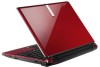
... pointing device which functions like the left and right buttons function like a computer mouse. For entering data into your new computer. Chapter 1 Your Gateway Notebook tour After learning about your computer features, let us show you around your computer. Display screen Keyboard TouchPad Battery/ Bluetooth/3G/ Wireless LAN communication indicator Also called Liquid-Crystal Display (LCD...
... pointing device which functions like the left and right buttons function like a computer mouse. For entering data into your new computer. Chapter 1 Your Gateway Notebook tour After learning about your computer features, let us show you around your computer. Display screen Keyboard TouchPad Battery/ Bluetooth/3G/ Wireless LAN communication indicator Also called Liquid-Crystal Display (LCD...

Service Guide
Page 17
... 3G connectivity (only for removal. Note: The battery shown is for reference only. Houses the computer's main memory. Rear and Base View No. 1 2 3 4 5 6 7 8 1 8 2 7 3 4 6 5 Icon Item Battery bay Battery release latch Hard disk bay 3G module bay Description Houses the computer's battery pack. Houses the computer's 3G communication module. Houses the computer's hard disk (secured with screws). Note: Do...
... 3G connectivity (only for removal. Note: The battery shown is for reference only. Houses the computer's main memory. Rear and Base View No. 1 2 3 4 5 6 7 8 1 8 2 7 3 4 6 5 Icon Item Battery bay Battery release latch Hard disk bay 3G module bay Description Houses the computer's battery pack. Houses the computer's 3G communication module. Houses the computer's hard disk (secured with screws). Note: Do...

Service Guide
Page 18
... is active. Indicates when the hard disk drive is closed. NOTE: 1. Charging: The battery light shows amber when the battery is activated. Battery Indicates the computer's battery status. Fully charged: The light shows green when in AC mode. 8 Chapter 1 Icon Function Bluetooth Description Indicates the status of 3G communication. Caps Lock Lights ...
... is active. Indicates when the hard disk drive is closed. NOTE: 1. Charging: The battery light shows amber when the battery is activated. Battery Indicates the computer's battery status. Fully charged: The light shows green when in AC mode. 8 Chapter 1 Icon Function Bluetooth Description Indicates the status of 3G communication. Caps Lock Lights ...
Service Guide
Page 29
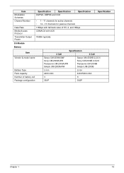
... Access Protocol Transmitter Output Power DQPSK, DBPSK and CCK • 1---11 channels for active channels • 12---13 channels for passive channels 11Mbps with fall back rates of 5.5, 2, and 1Mbps CSMA/CA with ACK 18dBm typically 3G Module Battery Item Vendor & model name Battery Type Specification 3 Cell 6 Cell Sanyo UM-2009A/AW Sony.../AW Simplo UM-2009A/AW Sanyo UM-2009B 2.2/2.6 Sony UM-2009B 2.2/2.6 Panasonic UM-2009B Simplo UM-2009B Li-ion Li-ion Pack capacity Number of battery cell Package configuration 2200 mAh 3 3S1P 4400/5200 mAh 6 3S2P Chapter 1 19
... Access Protocol Transmitter Output Power DQPSK, DBPSK and CCK • 1---11 channels for active channels • 12---13 channels for passive channels 11Mbps with fall back rates of 5.5, 2, and 1Mbps CSMA/CA with ACK 18dBm typically 3G Module Battery Item Vendor & model name Battery Type Specification 3 Cell 6 Cell Sanyo UM-2009A/AW Sony.../AW Simplo UM-2009A/AW Sanyo UM-2009B 2.2/2.6 Sony UM-2009B 2.2/2.6 Panasonic UM-2009B Simplo UM-2009B Li-ion Li-ion Pack capacity Number of battery cell Package configuration 2200 mAh 3 3S1P 4400/5200 mAh 6 3S2P Chapter 1 19

Service Guide
Page 39
... The BIOS flash memory update is not completely loaded. NOTE: Please use the AC adaptor power supply when you use the Phlash utility. If the battery pack does not contain enough power to update the system BIOS flash ROM. NOTE: If you do not have a crisis recovery diskette at hand, then...
... The BIOS flash memory update is not completely loaded. NOTE: Please use the AC adaptor power supply when you use the Phlash utility. If the battery pack does not contain enough power to update the system BIOS flash ROM. NOTE: If you do not have a crisis recovery diskette at hand, then...

Service Guide
Page 46
Place the system on a flat, stable surface. 4. Disassembly Process The disassembly process is divided into the following : 1. Remove the battery pack. Main Screw List Screw Quantity Part Number M2.0*3.0-I IRON 29 86.S0207.001 2.0*4.0 12 86.W0107.003 M2.0*6.0-I 7 86.S6507.001 M3*0.5+3.5I 4 86....
Place the system on a flat, stable surface. 4. Disassembly Process The disassembly process is divided into the following : 1. Remove the battery pack. Main Screw List Screw Quantity Part Number M2.0*3.0-I IRON 29 86.S0207.001 2.0*4.0 12 86.W0107.003 M2.0*6.0-I 7 86.S6507.001 M3*0.5+3.5I 4 86....

Service Guide
Page 47
External Modules Disassembly Flowchart Turn off system and peripherals power Disconnect power and signal cables from system Remove Battery Remove Lower Covers Remove HDD Remove DIMM Remove WLAN Board Remove 3g Board Screw List Step HDD Carrier WLAN Board HDD Module 3g Card Screw M3*0.5+3.5I M2*3 M2*3 M2*3 Quantity 4 1 2 2 Part No. 86.TDY07.003 86.S0207.001 86.S0207.001 86.S0207.001 Chapter 3 37 External Module Disassembly Process NOTE: The product previews seen in the disassembly procedures may not represent the final product color or configuration.
External Modules Disassembly Flowchart Turn off system and peripherals power Disconnect power and signal cables from system Remove Battery Remove Lower Covers Remove HDD Remove DIMM Remove WLAN Board Remove 3g Board Screw List Step HDD Carrier WLAN Board HDD Module 3g Card Screw M3*0.5+3.5I M2*3 M2*3 M2*3 Quantity 4 1 2 2 Part No. 86.TDY07.003 86.S0207.001 86.S0207.001 86.S0207.001 Chapter 3 37 External Module Disassembly Process NOTE: The product previews seen in the disassembly procedures may not represent the final product color or configuration.

Service Guide
Page 48
Removing the Battery Pack 1. Turn the computer over. 2. Slide and hold the battery release latch to the unlock position. 3. Slide the battery lock/unlock latch to the release position (1), then slide out the battery pack from the main unit (2). 2 1 38 Chapter 3
Removing the Battery Pack 1. Turn the computer over. 2. Slide and hold the battery release latch to the unlock position. 3. Slide the battery lock/unlock latch to the release position (1), then slide out the battery pack from the main unit (2). 2 1 38 Chapter 3

Service Guide
Page 49
See "Removing the Battery Pack" on page 38. 2. Chapter 3 39 Lift the HDD cover up to remove. Removing the Hard Disk Drive Module 1. Loosen the three captive screws in the HDD Cover. 3.
See "Removing the Battery Pack" on page 38. 2. Chapter 3 39 Lift the HDD cover up to remove. Removing the Hard Disk Drive Module 1. Loosen the three captive screws in the HDD Cover. 3.

Service Guide
Page 52
Lift the Memory cover up to remove. 42 Chapter 3 See "Removing the Battery Pack" on page 38. 2. Loosen the two captive screws in the Memory Cover. 3. Removing the DIMM Module 1.
Lift the Memory cover up to remove. 42 Chapter 3 See "Removing the Battery Pack" on page 38. 2. Loosen the two captive screws in the Memory Cover. 3. Removing the DIMM Module 1.

Service Guide
Page 54
Loosen the two captive screws in the 3G Cover. 3. See "Removing the Battery Pack" on page 38. 2. Lift the 3G cover up to remove. NOTE: The 3g card is also located under this cover. 44 Chapter 3 Removing the WLAN Board 1.
Loosen the two captive screws in the 3G Cover. 3. See "Removing the Battery Pack" on page 38. 2. Lift the 3G cover up to remove. NOTE: The 3g card is also located under this cover. 44 Chapter 3 Removing the WLAN Board 1.

Service Guide
Page 57
See "Removing the Battery Pack" on page 38. 2. NOTE: The WLAN card is also located under this cover. Chapter 3 47 Loosen the two captive screws in the 3G Cover. 3. Lift the 3G cover up to remove. Removing the 3g Board 1.
See "Removing the Battery Pack" on page 38. 2. NOTE: The WLAN card is also located under this cover. Chapter 3 47 Loosen the two captive screws in the 3G Cover. 3. Lift the 3G cover up to remove. Removing the 3g Board 1.

Service Guide
Page 59
... Remove CRT Board Remove LAN Board Remove Mainboard Remove Bluetooth Module Remove LED Board Remove Button Board Remove LCD Module Remove Thermal Module Remove RTC Battery Remove Speaker Modue Remove CPU Screw List Step Upper Cover Hinge Cover Button Board I/O Board VGA Board LCD Module LED Board Speaker Module Mainboard Thermal...
... Remove CRT Board Remove LAN Board Remove Mainboard Remove Bluetooth Module Remove LED Board Remove Button Board Remove LCD Module Remove Thermal Module Remove RTC Battery Remove Speaker Modue Remove CPU Screw List Step Upper Cover Hinge Cover Button Board I/O Board VGA Board LCD Module LED Board Speaker Module Mainboard Thermal...

Service Guide
Page 60
See "Removing the Battery Pack" on page 38. 2. Unlock the four securing latches by pressing down with a suitable plastic tool. Lift the Keyboard away from the Upper Cover; Turn the computer rightside up and open Keyboard FFC securing latch as shown. the Keyboard FFC is still attached. 5. Use plastic tools where available. 4. Turn the Keyboard over and open the lid to the full extent. 3. IMPORTANT: The use of metal tools may damage the outer casing. IMPORTANT: Do not remove the Keyboard from the Upper Cover as shown. 50 Chapter 3 Removing the Keyboard 1.
See "Removing the Battery Pack" on page 38. 2. Unlock the four securing latches by pressing down with a suitable plastic tool. Lift the Keyboard away from the Upper Cover; Turn the computer rightside up and open Keyboard FFC securing latch as shown. the Keyboard FFC is still attached. 5. Use plastic tools where available. 4. Turn the Keyboard over and open the lid to the full extent. 3. IMPORTANT: The use of metal tools may damage the outer casing. IMPORTANT: Do not remove the Keyboard from the Upper Cover as shown. 50 Chapter 3 Removing the Keyboard 1.

Service Guide
Page 62
Step Hinge Cover Size M2*10 Quantity 2 3. Screw Type 52 Chapter 3 See "Removing the Battery Pack" on page 38. 2. Pull the Hinge Covers away from the Upper Cover as shown. Remove the two screws securing the hinge covers. Removing the Hinge Covers 1.
Step Hinge Cover Size M2*10 Quantity 2 3. Screw Type 52 Chapter 3 See "Removing the Battery Pack" on page 38. 2. Pull the Hinge Covers away from the Upper Cover as shown. Remove the two screws securing the hinge covers. Removing the Hinge Covers 1.

Service Guide
Page 84
Removing the RTC Battery IMPORTANT: Follow local regulations for disposal of all batteries. 1. See "Removing the Mainboard" on page 72. 2. Disconnect the RTC Battery as shown. 74 Chapter 3
Removing the RTC Battery IMPORTANT: Follow local regulations for disposal of all batteries. 1. See "Removing the Mainboard" on page 72. 2. Disconnect the RTC Battery as shown. 74 Chapter 3

Service Guide
Page 106
Replacing the Mainboard 1. Insert the main board into the lower cover port-edge first. 96 Chapter 3 See "Removing the Mainboard" on page 72. 2. Replacing the RTC Battery IMPORTANT: Follow local regulations for disposal of all batteries. 1. Disconnect the RTC Battery as shown. 2. Turn the assembly and Mainboard onto its side and connect the mainboard to the VGA cable as shown.
Replacing the Mainboard 1. Insert the main board into the lower cover port-edge first. 96 Chapter 3 See "Removing the Mainboard" on page 72. 2. Replacing the RTC Battery IMPORTANT: Follow local regulations for disposal of all batteries. 1. Disconnect the RTC Battery as shown. 2. Turn the assembly and Mainboard onto its side and connect the mainboard to the VGA cable as shown.


