Gateway E-9525R Server User Guide
Page 3
... up the operating system 19 Initial hardware settings 19 Chapter 3: Maintaining Your Server 21 Caring for your server 22 Cleaning your server 22 Preparing for system recovery 23 Recording the BIOS configuration 23 System administration 23 Gateway Systems Manager 23 Server security 24 Identifying your server 24 Updating the baseboard management controller firmware 25 Using your...
... up the operating system 19 Initial hardware settings 19 Chapter 3: Maintaining Your Server 21 Caring for your server 22 Cleaning your server 22 Preparing for system recovery 23 Recording the BIOS configuration 23 System administration 23 Gateway Systems Manager 23 Server security 24 Identifying your server 24 Updating the baseboard management controller firmware 25 Using your...
Gateway E-9525R Server User Guide
Page 4
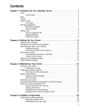
Contents Getting Help 30 Preventing static electricity discharge 30 Opening the server case 31 Closing the server case 32 Installing and removing drives 33 Removing and installing an optical drive 33 Removing and installing a tape drive 35 Removing and installing a hard ... 63 Updating and recovering the BMC 64 Updating the BMC firmware 64 Recovering the BMC 65 Chapter 6: Troubleshooting 67 Telephone support 68 Before calling Gateway Customer Care 68 Telephone support 68 Tutoring and training 69 Safety guidelines 69 Error messages 69 Troubleshooting 73 First steps 73 ii
Contents Getting Help 30 Preventing static electricity discharge 30 Opening the server case 31 Closing the server case 32 Installing and removing drives 33 Removing and installing an optical drive 33 Removing and installing a tape drive 35 Removing and installing a hard ... 63 Updating and recovering the BMC 64 Updating the BMC firmware 64 Recovering the BMC 65 Chapter 6: Troubleshooting 67 Telephone support 68 Before calling Gateway Customer Care 68 Telephone support 68 Tutoring and training 69 Safety guidelines 69 Error messages 69 Troubleshooting 73 First steps 73 ii

Gateway E-9525R Server User Guide
Page 5
www.gateway.com Battery replacement 73 Beep codes 74 LED information 75 Diagnostic LEDs 76 BIOS 81 Optical drive 81 Expansion cards 82 Hard drive 82 Internet 83 Keyboard 83 Memory 83 Monitor 83 Power 84 Processor 84 Appendix A: Server Specifications 85 System specifications 86 System board specifications 86 Environmental specifications 87 Electronic specifications 87 Memory map 87 Interrupts 88 Connector pinouts 88 Additional specifications 91 Appendix B: BIOS Settings 93 Appendix C: Legal Information 103 Appendix D: Safety Information 107 iii
www.gateway.com Battery replacement 73 Beep codes 74 LED information 75 Diagnostic LEDs 76 BIOS 81 Optical drive 81 Expansion cards 82 Hard drive 82 Internet 83 Keyboard 83 Memory 83 Monitor 83 Power 84 Processor 84 Appendix A: Server Specifications 85 System specifications 86 System board specifications 86 Environmental specifications 87 Electronic specifications 87 Memory map 87 Interrupts 88 Connector pinouts 88 Additional specifications 91 Appendix B: BIOS Settings 93 Appendix C: Legal Information 103 Appendix D: Safety Information 107 iii

Gateway E-9525R Server User Guide
Page 7
CHAPTER 1 Checking Out Your Gateway Server • Front • Back • Interior • System board • Hot-swap backplanes • Getting Help 1
CHAPTER 1 Checking Out Your Gateway Server • Front • Back • Interior • System board • Hot-swap backplanes • Getting Help 1

Gateway E-9525R Server User Guide
Page 8
Front CHAPTER 1: Checking Out Your Gateway Server Hard drives Hard drive tray LEDs Control panel Optical drive Control panel # Feature 1 Power button 2 Power LED 3 Reset button 4 NMI button 5 System fault LED 6 NIC status LED 2 # Feature 7 SMIL module plug 8 VGA connector 9 Dual USB ports 10 ID button 11 ID LED
Front CHAPTER 1: Checking Out Your Gateway Server Hard drives Hard drive tray LEDs Control panel Optical drive Control panel # Feature 1 Power button 2 Power LED 3 Reset button 4 NMI button 5 System fault LED 6 NIC status LED 2 # Feature 7 SMIL module plug 8 VGA connector 9 Dual USB ports 10 ID button 11 ID LED

Gateway E-9525R Server User Guide
Page 9
Back www.gateway.com Dual NIC connectors PS/2 Keyboard port VGA port Serial port Server management port PS/2 Mouse port ID LED Dual USB ports SAS JBOD connector (optional) Power supply AC power connector 3
Back www.gateway.com Dual NIC connectors PS/2 Keyboard port VGA port Serial port Server management port PS/2 Mouse port ID LED Dual USB ports SAS JBOD connector (optional) Power supply AC power connector 3
Gateway E-9525R Server User Guide
Page 10
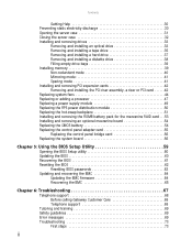
Interior CHAPTER 1: Checking Out Your Gateway Server # Feature # Feature 1 System board 9 Control panel adapter card 2 Fan duct 10 SAS/SATA backplane 3 System fans 11 System fans 4 Tape drive (optional) 12 System fans 5 Slimline DVD/CD-RW combo drive or 13 RPS power distribution module DVD-RW drive 6 Diskette drive (optional) 14 Riser card assembly 7 SMIL module (optional) 15 ROMB battery pack for mezzanine RAID card 8 Hard drive bays 16 Power supply 4
Interior CHAPTER 1: Checking Out Your Gateway Server # Feature # Feature 1 System board 9 Control panel adapter card 2 Fan duct 10 SAS/SATA backplane 3 System fans 11 System fans 4 Tape drive (optional) 12 System fans 5 Slimline DVD/CD-RW combo drive or 13 RPS power distribution module DVD-RW drive 6 Diskette drive (optional) 14 Riser card assembly 7 SMIL module (optional) 15 ROMB battery pack for mezzanine RAID card 8 Hard drive bays 16 Power supply 4

Gateway E-9525R Server User Guide
Page 14
...) On = Power is on Green (On) - NIC 1 Gbps activity LED 1 (Off) - Hard drive rebuilding Off - CHAPTER 1: Checking Out Your Gateway Server LED information See the following table for a description of this server's LEDs and the information they provide: LED Name Function Location Color Description ID Aid in... server Control panel and Yellow On = Server identification identification back of the system AC power LED Identify power supply fault Power supply module Blue Green or Orange ...
...) On = Power is on Green (On) - NIC 1 Gbps activity LED 1 (Off) - Hard drive rebuilding Off - CHAPTER 1: Checking Out Your Gateway Server LED information See the following table for a description of this server's LEDs and the information they provide: LED Name Function Location Color Description ID Aid in... server Control panel and Yellow On = Server identification identification back of the system AC power LED Identify power supply fault Power supply module Blue Green or Orange ...

Gateway E-9525R Server User Guide
Page 15
... asked questions (FAQs) Telephone support You can use the following information resources to help you use your server. Gateway Web site Gateway provides a variety of services through your telephone, including customer service, technical support, and information services. For more information,... see Using Your Server Companion DVD. www.gateway.com Getting Help In addition to your operating system's documentation, you can access a wide range of information on ...
... asked questions (FAQs) Telephone support You can use the following information resources to help you use your server. Gateway Web site Gateway provides a variety of services through your telephone, including customer service, technical support, and information services. For more information,... see Using Your Server Companion DVD. www.gateway.com Getting Help In addition to your operating system's documentation, you can access a wide range of information on ...

Gateway E-9525R Server User Guide
Page 16
CHAPTER 1: Checking Out Your Gateway Server 10
CHAPTER 1: Checking Out Your Gateway Server 10

Gateway E-9525R Server User Guide
Page 17
CHAPTER 2 Setting Up Your Server • Setting up the hardware • Protecting from power source problems • Mounting your server into a cabinet • Starting your server • Setting up the operating system • Initial hardware settings 11
CHAPTER 2 Setting Up Your Server • Setting up the hardware • Protecting from power source problems • Mounting your server into a cabinet • Starting your server • Setting up the operating system • Initial hardware settings 11

Gateway E-9525R Server User Guide
Page 18
..., the better the protection for your location, such as a television or a motor. 12 For additional protection from reaching your server. Protect your server by connecting them to pass through the power cord and the modem and network connections. If you purchase a surge protector: •...; Make sure that causes electromagnetic interference, such as Underwriters Laboratories (UL). • Check the maximum amount of electricity coming into your server can erase data on both diskettes and hard drives. Use a surge protector, UPS, or wall outlet that is located near, or shares ...
..., the better the protection for your location, such as a television or a motor. 12 For additional protection from reaching your server. Protect your server by connecting them to pass through the power cord and the modem and network connections. If you purchase a surge protector: •...; Make sure that causes electromagnetic interference, such as Underwriters Laboratories (UL). • Check the maximum amount of electricity coming into your server can erase data on both diskettes and hard drives. Use a surge protector, UPS, or wall outlet that is located near, or shares ...

Gateway E-9525R Server User Guide
Page 19
... Stud (installed) Stud Locking screw (installed) 2 Align the locking screw holes in the kit. To buy a UPS, visit www.gateway.com. If your server from the cabinet manufacturer. A UPS uses a battery to protect your cabinet is turned off and all power cords are unplugged. Caution The ...obtain mounting hardware from data loss during a power failure and lets you ordered the optional tooless-rail kit for an extended period of the server to the instructions included in the rails with the studs and slide the rails forward until they stop. The fixed-rail cabinet mounting hardware...
... Stud (installed) Stud Locking screw (installed) 2 Align the locking screw holes in the kit. To buy a UPS, visit www.gateway.com. If your server from the cabinet manufacturer. A UPS uses a battery to protect your cabinet is turned off and all power cords are unplugged. Caution The ...obtain mounting hardware from data loss during a power failure and lets you ordered the optional tooless-rail kit for an extended period of the server to the instructions included in the rails with the studs and slide the rails forward until they stop. The fixed-rail cabinet mounting hardware...

Gateway E-9525R Server User Guide
Page 20
Locking screw (installed) Back server rail Stud (installed) Stud 4 Align the locking screw holes in the server, then install one locking screw through the each of the server, then engage the slots with the threaded screw holes in the rails with the studs and slide the rail forward until it stops. Front cabinet post Mounting nut 14 CHAPTER 2: Setting Up Your Server 3 Align the slots in the back server rails with the studs on the side of the two front cabinet posts where you plan to each back server rail. 5 Attach one mounting nut to install the server.
Locking screw (installed) Back server rail Stud (installed) Stud 4 Align the locking screw holes in the server, then install one locking screw through the each of the server, then engage the slots with the threaded screw holes in the rails with the studs and slide the rail forward until it stops. Front cabinet post Mounting nut 14 CHAPTER 2: Setting Up Your Server 3 Align the slots in the back server rails with the studs on the side of the two front cabinet posts where you plan to each back server rail. 5 Attach one mounting nut to install the server.

Gateway E-9525R Server User Guide
Page 21
www.gateway.com 6 Attach one on each of the two back cabinet posts where you plan to each side). Mounting screw 15 If the server is not supported, damage to the server or injury may result. 7 Hold the server in place in the cabinet and swing the hinged back rail mounting brackets into alignment with the mounting nuts, then secure the back in place with two mounting screws (one mounting nut to install the server. Back cabinet post Mounting nut Hinged back rail mounting bracket Warning You must support the server while installing or removing the front and back mounting screws.
www.gateway.com 6 Attach one on each of the two back cabinet posts where you plan to each side). Mounting screw 15 If the server is not supported, damage to the server or injury may result. 7 Hold the server in place in the cabinet and swing the hinged back rail mounting brackets into alignment with the mounting nuts, then secure the back in place with two mounting screws (one mounting nut to install the server. Back cabinet post Mounting nut Hinged back rail mounting bracket Warning You must support the server while installing or removing the front and back mounting screws.

Gateway E-9525R Server User Guide
Page 22
Mounting bracket Mounting bracket 2 Attach the handles to the sides of the server with the small holes in the mounting brackets on the front side of the server. Installing the bezel To install the bezel: 1 With the server pulled out from the cabinet, align the holes in the handle with two mounting screws on each side. 16 CHAPTER 2: Setting Up Your Server 8 Align the mounting screw holes in the server handles with the front mounting nuts, then secure the front in place with two mounting screws (one on each side).
Mounting bracket Mounting bracket 2 Attach the handles to the sides of the server with the small holes in the mounting brackets on the front side of the server. Installing the bezel To install the bezel: 1 With the server pulled out from the cabinet, align the holes in the handle with two mounting screws on each side. 16 CHAPTER 2: Setting Up Your Server 8 Align the mounting screw holes in the server handles with the front mounting nuts, then secure the front in place with two mounting screws (one on each side).

Gateway E-9525R Server User Guide
Page 23
... 4 When the bezel is not supported, damage to support the front of the server. You must support the server while removing the front screws and while sliding the server off the cabinet rails. www.gateway.com Back view Handle Mounting screw Front view Mounting bracket Mounting bracket Mounting screw ... and turning it clockwise until it stops (approximately ¼ turn). 5 Put the key in the cabinet. 2 While supporting the server, slide the server out from a cabinet: Warning Screws are required to the server or injury may result. 1 Remove the thumbscrews through the handles that hold the...
... 4 When the bezel is not supported, damage to support the front of the server. You must support the server while removing the front screws and while sliding the server off the cabinet rails. www.gateway.com Back view Handle Mounting screw Front view Mounting bracket Mounting bracket Mounting screw ... and turning it clockwise until it stops (approximately ¼ turn). 5 Put the key in the cabinet. 2 While supporting the server, slide the server out from a cabinet: Warning Screws are required to the server or injury may result. 1 Remove the thumbscrews through the handles that hold the...

Gateway E-9525R Server User Guide
Page 24
...power outlet or surge protector, and turned on. Understanding the power-on self-test When you turn on self-test (POST) routine checks the server memory and components. The Power LED (2) lights. If nothing happens when you press the power button: • Make sure that the power ... are connected securely to the correct ports and jacks on the back of the power loss, contact Gateway Customer Care. If POST finds any pre-installed operating system may also need to the server. 2 Press the power button (1). You may begin asking you for configuration settings. For more information...
...power outlet or surge protector, and turned on. Understanding the power-on self-test When you turn on self-test (POST) routine checks the server memory and components. The Power LED (2) lights. If nothing happens when you press the power button: • Make sure that the power ... are connected securely to the correct ports and jacks on the back of the power loss, contact Gateway Customer Care. If POST finds any pre-installed operating system may also need to the server. 2 Press the power button (1). You may begin asking you for configuration settings. For more information...

Gateway E-9525R Server User Guide
Page 25
... tasking change, a change in most cases it was not already installed by Gateway, see "Using the BIOS Setup Utility" on shutting down the operating system. To remove AC power from the server, you must unplug the AC power cords from the manufacturer with the operating system...If you ordered your operating system's documentation for instructions. General hardware settings can be changed by Gateway, in security requirements, or the addition of pressing the power button. 2 If your server, first shut down the operating system. For information on the BIOS Setup utility, see the...
... tasking change, a change in most cases it was not already installed by Gateway, see "Using the BIOS Setup Utility" on shutting down the operating system. To remove AC power from the server, you must unplug the AC power cords from the manufacturer with the operating system...If you ordered your operating system's documentation for instructions. General hardware settings can be changed by Gateway, in security requirements, or the addition of pressing the power button. 2 If your server, first shut down the operating system. For information on the BIOS Setup utility, see the...

Gateway E-9525R Server User Guide
Page 27
CHAPTER 3 Maintaining Your Server • Caring for your server • Preparing for system recovery • System administration • Identifying your server • Updating the baseboard management controller firmware • Using your Server Companion DVD 21
CHAPTER 3 Maintaining Your Server • Caring for your server • Preparing for system recovery • System administration • Identifying your server • Updating the baseboard management controller firmware • Using your Server Companion DVD 21