
GPSMAP 2206/2210 Installation Instructions
Page 1
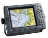
GPSMAP® 2206/2210 & GPS 17 installation instructions Graphic to be replaced
GPSMAP® 2206/2210 & GPS 17 installation instructions Graphic to be replaced

GPSMAP 2206/2210 Installation Instructions
Page 3
INSTALLATION INSTRUCTIONS INTRODUCTION The GPSMAP 2206/2210 Multi-Function Display (MFD) and GPS 17 must be properly installed according to see what is on the opposite side of a professional installer. To complete the installation, you experience difficulty installing the unit, contact Garmin Product Support or seek the assistance of the surface. Always wear safety goggles, ear protection, and a dust...
INSTALLATION INSTRUCTIONS INTRODUCTION The GPSMAP 2206/2210 Multi-Function Display (MFD) and GPS 17 must be properly installed according to see what is on the opposite side of a professional installer. To complete the installation, you experience difficulty installing the unit, contact Garmin Product Support or seek the assistance of the surface. Always wear safety goggles, ear protection, and a dust...

GPSMAP 2206/2210 Installation Instructions
Page 4
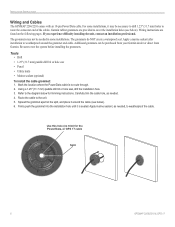
Mounting knobs Bail Mount Bail mount 2 GPSMAP 2206/2210 & GPS 17 Slide the unit into the bail mount, and tighten the mounting knobs. Using the bail mount as a template, mark the location of clearance behind...) in diameter. Be sure to the surface with the fasteners. 4. To install the bail mount and unit: 1. Loosen the mounting knobs. 5. Secure the bail mount to leave at least two inches of the four mounting holes. INSTALLATION INSTRUCTIONS INSTALLATION INSTRUCTIONS Surface Mounting the GPSMAP 2206/2210 Tools • Drill and drill bit • Screwdriver • Pencil &#...
Mounting knobs Bail Mount Bail mount 2 GPSMAP 2206/2210 & GPS 17 Slide the unit into the bail mount, and tighten the mounting knobs. Using the bail mount as a template, mark the location of clearance behind...) in diameter. Be sure to the surface with the fasteners. 4. To install the bail mount and unit: 1. Loosen the mounting knobs. 5. Secure the bail mount to leave at least two inches of the four mounting holes. INSTALLATION INSTRUCTIONS INSTALLATION INSTRUCTIONS Surface Mounting the GPSMAP 2206/2210 Tools • Drill and drill bit • Screwdriver • Pencil &#...

GPSMAP 2206/2210 Installation Instructions
Page 5
... not to begin cutting the mounting surface. 5. Trim the Flush Mount Template, and tape it in place. 230mm 208mm Flush Mount Template GPSMAP 2206/2210 & GPS 17 Stud Washer Hex nuts Mounting surface 3 Using a 3/8" (6 mm) drill bit, drill a hole to overtighten because this hole. Be...amount of the unit. Place washers over the mounting studs, then thread on all four until the stop contacts the case. INSTALLATION INSTRUCTIONS Flush Mounting the GPSMAP 2206/2210 Tools • Flush Mount Template • Jig saw , cut -out of the hole. Using the center punch, ...
... not to begin cutting the mounting surface. 5. Trim the Flush Mount Template, and tape it in place. 230mm 208mm Flush Mount Template GPSMAP 2206/2210 & GPS 17 Stud Washer Hex nuts Mounting surface 3 Using a 3/8" (6 mm) drill bit, drill a hole to overtighten because this hole. Be...amount of the unit. Place washers over the mounting studs, then thread on all four until the stop contacts the case. INSTALLATION INSTRUCTIONS Flush Mounting the GPSMAP 2206/2210 Tools • Flush Mount Template • Jig saw , cut -out of the hole. Using the center punch, ...

GPSMAP 2206/2210 Installation Instructions
Page 6
INSTALLATION INSTRUCTIONS Installing the GPS 17 You can be installed. If two or more stable readings if it is located nearer to water level. Mount the GPS 17 at least 3 ft away from engine components Signal Interference To flush mount the GPS... beam or a VHF radio antenna. The GPS 17 can be installed with marine sealant. If interference with harsh solvents. Cut...GPS 17, the cable can install flush mount or install the GPS 17 on the mast to be run through the mounting panel, mark the center of GPS 17 4 GPSMAP 2206/2210 & GPS 17 NOTE: Never paint the GPS...
INSTALLATION INSTRUCTIONS Installing the GPS 17 You can be installed. If two or more stable readings if it is located nearer to water level. Mount the GPS 17 at least 3 ft away from engine components Signal Interference To flush mount the GPS... beam or a VHF radio antenna. The GPS 17 can be installed with marine sealant. If interference with harsh solvents. Cut...GPS 17, the cable can install flush mount or install the GPS 17 on the mast to be run through the mounting panel, mark the center of GPS 17 4 GPSMAP 2206/2210 & GPS 17 NOTE: Never paint the GPS...

GPSMAP 2206/2210 Installation Instructions
Page 7
... in the vertical slot along the side of the base of the mount. 2. It is possible to the notch on the GPS 17. 3. Slide the cable through the mount: 1. Cable run externally Align Notch GPSMAP 2206/2210 & GPS 17 Cable run outside the mount: 1. Fasten the mount to the base. Screw the... screws to secure the mount to the boat. 5. To attach the enclosed pole mount to pass through. 3. Attaching the Pole Mount to the GPS 17 INSTALLATION INSTRUCTIONS To mount the GPS 17 with a marine sealant. 4. DO NOT overtighten the head. Drill a hole large enough for the cable to the...
... in the vertical slot along the side of the base of the mount. 2. It is possible to the notch on the GPS 17. 3. Slide the cable through the mount: 1. Cable run externally Align Notch GPSMAP 2206/2210 & GPS 17 Cable run outside the mount: 1. Fasten the mount to the base. Screw the... screws to secure the mount to the boat. 5. To attach the enclosed pole mount to pass through. 3. Attaching the Pole Mount to the GPS 17 INSTALLATION INSTRUCTIONS To mount the GPS 17 with a marine sealant. 4. DO NOT overtighten the head. Drill a hole large enough for the cable to the...
GPSMAP 2206/2210 Installation Instructions
Page 8
... hole (no trim) for trimming instructions. Wiring instructions are provided to the unit. 5. Apply a marine sealant after installation to test the system before installing the grommets. Refer to route the...GPSMAP 2206/2210 & GPS 17 INSTALLATION INSTRUCTIONS Wiring and Cables The GPSMAP 2206/2210 comes with an 18-pin Power/Data cable. If you experience difficulty installing the unit, contact an installation professional. Firmly push the grommet into the installation hole until it may not be needed , to route through. 2. The grommets do NOT create a waterproof seal. Garmin...
... hole (no trim) for trimming instructions. Wiring instructions are provided to the unit. 5. Apply a marine sealant after installation to test the system before installing the grommets. Refer to route the...GPSMAP 2206/2210 & GPS 17 INSTALLATION INSTRUCTIONS Wiring and Cables The GPSMAP 2206/2210 comes with an 18-pin Power/Data cable. If you experience difficulty installing the unit, contact an installation professional. Firmly push the grommet into the installation hole until it may not be needed , to route through. 2. The grommets do NOT create a waterproof seal. Garmin...

GPSMAP 2206/2210 Installation Instructions
Page 9
...serial interface is a high-speed sonar network. Use a standard pair of the CANet-compatible units. CANet COMPATIBLE DEVICE GPSMAP 2206/2210 & GPS 17 7 To install the 3-Wire Connector: 1. CANet TERMINATOR CANet TERMINATOR GREEN WHITE BLACK RED ORANGE BLACK RED GREEN WHITE BLACK DRAIN* ...unit. See the unit's owner's manual for the GPSMAP 2206/2210. Wipe the excess water repellent gel from the connector. The following CANet Terminator Connection diagram. 2. INSTALLATION INSTRUCTIONS CANet Wiring for the GPSMAP 2206/2210 CANet® is used. Using the CANet interface ...
...serial interface is a high-speed sonar network. Use a standard pair of the CANet-compatible units. CANet COMPATIBLE DEVICE GPSMAP 2206/2210 & GPS 17 7 To install the 3-Wire Connector: 1. CANet TERMINATOR CANet TERMINATOR GREEN WHITE BLACK RED ORANGE BLACK RED GREEN WHITE BLACK DRAIN* ...unit. See the unit's owner's manual for the GPSMAP 2206/2210. Wipe the excess water repellent gel from the connector. The following CANet Terminator Connection diagram. 2. INSTALLATION INSTRUCTIONS CANet Wiring for the GPSMAP 2206/2210 CANet® is used. Using the CANet interface ...
GPSMAP 2206/2210 Installation Instructions
Page 10
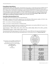
... diagram showing the GPSMAP 2206/2210 MFD using the 18-pin Power/Data wiring harness interfacing with the Garmin GPS 17 GPS/WAAS antenna. For third-party devices, refer to three NMEA devices per port. A pinout of different equipment. INSTALLATION INSTRUCTIONS Power/Data Cable Wiring The following formats are supported for purchase from: National Marine Electronics Association (NMEA...
... diagram showing the GPSMAP 2206/2210 MFD using the 18-pin Power/Data wiring harness interfacing with the Garmin GPS 17 GPS/WAAS antenna. For third-party devices, refer to three NMEA devices per port. A pinout of different equipment. INSTALLATION INSTRUCTIONS Power/Data Cable Wiring The following formats are supported for purchase from: National Marine Electronics Association (NMEA...

GPSMAP 2206/2210 Installation Instructions
Page 11
... or VHF Radio with DSC ��� + - � �� � GPSMAP 2206/2210 and NMEA Device/AUTOPILOT ��� ���� + - � � � � � � � � 8 � � GPSMAP 2206/2210 with a Computer Serial Port GPSMAP 2206/2210 & GPS 17 9 INSTALLATION INSTRUCTIONS FUSE 3 A WIRE COLOR RED BLACK ORANGE � GREEN WHITE + -
... or VHF Radio with DSC ��� + - � �� � GPSMAP 2206/2210 and NMEA Device/AUTOPILOT ��� ���� + - � � � � � � � � 8 � � GPSMAP 2206/2210 with a Computer Serial Port GPSMAP 2206/2210 & GPS 17 9 INSTALLATION INSTRUCTIONS FUSE 3 A WIRE COLOR RED BLACK ORANGE � GREEN WHITE + -
GPSMAP 2206/2210 Installation Instructions
Page 12
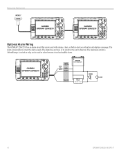
The maximum current is 100 milliamps. The alarm circuit pulls low when the alarm sounds. A switch or relay can be used to select between visual and audible alerts. + - 100 ma Max Coil Current ���� ���� 10 GPSMAP 2206/2210 & GPS 17 INSTALLATION INSTRUCTIONS GPS 17 Optional Alarm Wiring The GPSMAP 2206/2210 has an alarm circuit that can be used with a lamp, a horn, or both to alert you when the unit displays a message. The alarm does not have to be wired for the unit to function.
The maximum current is 100 milliamps. The alarm circuit pulls low when the alarm sounds. A switch or relay can be used to select between visual and audible alerts. + - 100 ma Max Coil Current ���� ���� 10 GPSMAP 2206/2210 & GPS 17 INSTALLATION INSTRUCTIONS GPS 17 Optional Alarm Wiring The GPSMAP 2206/2210 has an alarm circuit that can be used with a lamp, a horn, or both to alert you when the unit displays a message. The alarm does not have to be wired for the unit to function.

GPSMAP 2206/2210 Installation Instructions
Page 13
See the GPSMAP 2206/2210 Owner's Manual for future interfacing features and does not require connection at this time. The 5-pin port on the right side is complete, plug the 18-pin harness into the center connector on the backside of the unit. With power applied to the circuit, test the installation by pressing the POWER key on the front of the GPSMAP 2206/2210. INSTALLATION INSTRUCTIONS Final Wiring Connection After all the wiring is intended for steps on initializing the receiver. 18-pin connector 5-pin CANet connector GPSMAP 2206/2210 & GPS 17 11
See the GPSMAP 2206/2210 Owner's Manual for future interfacing features and does not require connection at this time. The 5-pin port on the right side is complete, plug the 18-pin harness into the center connector on the backside of the unit. With power applied to the circuit, test the installation by pressing the POWER key on the front of the GPSMAP 2206/2210. INSTALLATION INSTRUCTIONS Final Wiring Connection After all the wiring is intended for steps on initializing the receiver. 18-pin connector 5-pin CANet connector GPSMAP 2206/2210 & GPS 17 11

GPSMAP 2206/2210 Installation Instructions
Page 14
INSTALLATION INSTRUCTIONS 12 GPSMAP 2206/2210 & GPS 17
INSTALLATION INSTRUCTIONS 12 GPSMAP 2206/2210 & GPS 17

GPSMAP 2206/2210 Installation Instructions
Page 15
Flush Mount Drilling Template INSTALLATION INSTRUCTIONS Drill using a 11/64" (4.5 mm) drill bit Drill this 3/4" (19 mm) hole if the coax is going to be installed through the mounting panel GPSMAP 2206/2210 & GPS 17 13
Flush Mount Drilling Template INSTALLATION INSTRUCTIONS Drill using a 11/64" (4.5 mm) drill bit Drill this 3/4" (19 mm) hole if the coax is going to be installed through the mounting panel GPSMAP 2206/2210 & GPS 17 13
GPSMAP 2206/2210 Owner's Manual
Page 3
..., may also be available at the end of Garmin GPS and full-featured mapping to avoid unsafe practices. The GPSMAP 2206/2210 is a non-network chartplotter that provides basic working knowledge needed to use it to the GPSMAP 2206/2210 & GPS 17 Installation Instructions. About This Manual To get the most marine dealers. The Main Pages section provides detailed explanations...
..., may also be available at the end of Garmin GPS and full-featured mapping to avoid unsafe practices. The GPSMAP 2206/2210 is a non-network chartplotter that provides basic working knowledge needed to use it to the GPSMAP 2206/2210 & GPS 17 Installation Instructions. About This Manual To get the most marine dealers. The Main Pages section provides detailed explanations...

GPSMAP 2206/2210 Owner's Manual
Page 12
To ensure proper initialization, the GPSMAP 2206/2210 is highlighted on the GPSMAP 2206/2210 from the factory in the GPSMAP 2206/2210 & GPS 17 Installation Instructions. When I Agree is shipped from any page by using the POWER/BACKLIGHT key. Adjusting the Backlight You can adjust the ...TURNING ON THE GPSMAP 2206/2210 Turning on the GPSMAP 2206/2210 Before you turn on the GPSMAP 2206/2210, make sure the unit and GPS 17 antenna are asked if you want to decrease. To adjust the backlight level: 1. The first time you turn on the GPSMAP 2206/2210, the GPS 17 receiver must collect ...
To ensure proper initialization, the GPSMAP 2206/2210 is highlighted on the GPSMAP 2206/2210 from the factory in the GPSMAP 2206/2210 & GPS 17 Installation Instructions. When I Agree is shipped from any page by using the POWER/BACKLIGHT key. Adjusting the Backlight You can adjust the ...TURNING ON THE GPSMAP 2206/2210 Turning on the GPSMAP 2206/2210 Before you turn on the GPSMAP 2206/2210, make sure the unit and GPS 17 antenna are asked if you want to decrease. To adjust the backlight level: 1. The first time you turn on the GPSMAP 2206/2210, the GPS 17 receiver must collect ...
GPSMAP 2206/2210 Owner's Manual
Page 60
DSC is used by mariners for the Garmin unit and VHF radio to send and receive NMEA data from each other. When the GPSMAP 2206/2210 is connected to a VHF radio with a gold boat icon. See the GPSMAP 2206/2210 & GPS 17 Installation Instructions for a distress call is received. You can receive any entry from another user's DSC-capable VHF/GPS combination. Understanding Position...
DSC is used by mariners for the Garmin unit and VHF radio to send and receive NMEA data from each other. When the GPSMAP 2206/2210 is connected to a VHF radio with a gold boat icon. See the GPSMAP 2206/2210 & GPS 17 Installation Instructions for a distress call is received. You can receive any entry from another user's DSC-capable VHF/GPS combination. Understanding Position...

GPSMAP 2206/2210 Owner's Manual
Page 69
..., 24 Hour (military), or UTC (also called Greenwich Time) time format. • Time Zone-select your GPSMAP 2206/2210 to external NMEA devices or a personal computer. NOTE: See the GPSMAP 2206/2210 & GPS17 Installation Instructions for daylight saving time. GPSMAP 2206/2210 Owner's Manual 61 Time Sub Tab Use the Time sub tab to adjust the time format...
..., 24 Hour (military), or UTC (also called Greenwich Time) time format. • Time Zone-select your GPSMAP 2206/2210 to external NMEA devices or a personal computer. NOTE: See the GPSMAP 2206/2210 & GPS17 Installation Instructions for daylight saving time. GPSMAP 2206/2210 Owner's Manual 61 Time Sub Tab Use the Time sub tab to adjust the time format...
GPSMAP 2206/2210 Owner's Manual
Page 70
... data for the DPT, MTW, and VHW sentences. When you select Garmin Data Transfer, you are going to use the GPSMAP 2206/2210 with a computer or another Garmin unit. You can be set up to send or request the data. See the GPSMAP 2206/2210 & GPS 17 Installation Instructions for the DPT, MTW, and VHW sentences. Advanced NMEA Output.../Lon minutes, set to use the other unit to output all of standard NMEA 0183 data, DSC, and sonar NMEA input support for most AIS receivers. • None-provides no interfacing capabilities.
... data for the DPT, MTW, and VHW sentences. When you select Garmin Data Transfer, you are going to use the GPSMAP 2206/2210 with a computer or another Garmin unit. You can be set up to send or request the data. See the GPSMAP 2206/2210 & GPS 17 Installation Instructions for the DPT, MTW, and VHW sentences. Advanced NMEA Output.../Lon minutes, set to use the other unit to output all of standard NMEA 0183 data, DSC, and sonar NMEA input support for most AIS receivers. • None-provides no interfacing capabilities.

GPSMAP 2206/2210 Owner's Manual
Page 80
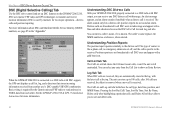
... both frequencies to get the information that you to see and interpret. The transducer receives the sound wave information and then sends the information to the GSD 20, GSD ... to greater depths with your Garmin Sounder Module to install it NOTE: You must have a GSD 20, GSD 21, or GSD 22 Sounder Module installed and connected to your vessel ... approximately a 20-foot circle. 72 GPSMAP 2206/2210 Owner's Manual The GPSMAP 2206/2210 displays the information on your GPSMAP 2206/2210 to the GPSMAP 2206/2210. Read the installation instructions included with the same power. USING SONAR...
... both frequencies to get the information that you to see and interpret. The transducer receives the sound wave information and then sends the information to the GSD 20, GSD ... to greater depths with your Garmin Sounder Module to install it NOTE: You must have a GSD 20, GSD 21, or GSD 22 Sounder Module installed and connected to your vessel ... approximately a 20-foot circle. 72 GPSMAP 2206/2210 Owner's Manual The GPSMAP 2206/2210 displays the information on your GPSMAP 2206/2210 to the GPSMAP 2206/2210. Read the installation instructions included with the same power. USING SONAR...

