Manual/User Guide
Page 1
C141-E144 C141-E202-01EN 3-1 For information about handling this hard disk drive and the system installation procedure, refer to the following Integration Guide. CHAPTER 3 Installation Conditions 3.1 Dimensions 3.2 Mounting 3.3 Cable Connections 3.4 Jumper Settings This chapter gives the external dimensions, installation conditions, surface temperature conditions, cable connections, and switch settings of the hard disk drives.
C141-E144 C141-E202-01EN 3-1 For information about handling this hard disk drive and the system installation procedure, refer to the following Integration Guide. CHAPTER 3 Installation Conditions 3.1 Dimensions 3.2 Mounting 3.3 Cable Connections 3.4 Jumper Settings This chapter gives the external dimensions, installation conditions, surface temperature conditions, cable connections, and switch settings of the hard disk drives.
Manual/User Guide
Page 2
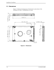
All dimensions are in mm. Figure 3.1 Dimensions 3-2 C141-E202-01EN Installation Conditions 3.1 Dimensions Figure 3.1 illustrates the dimensions of the disk drive and positions of the mounting screw holes.
All dimensions are in mm. Figure 3.1 Dimensions 3-2 C141-E202-01EN Installation Conditions 3.1 Dimensions Figure 3.1 illustrates the dimensions of the disk drive and positions of the mounting screw holes.
Manual/User Guide
Page 3
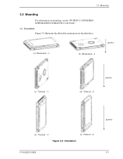
3.2 Mounting 3.2 Mounting For information on mounting, see the "FUJITSU 2.5-INCH HDD INTEGRATION GUIDANCE (C141-E144)." (1) Orientation Figure 3.2 illustrates the allowable orientations for the disk drive. gravity (a) Horizontal -1 (b) Horizontal -1 (c) Vertical -1 gravity (d) Vertical -2 gravity (e) Vertical -3 (f) Vertical -4 Figure 3.2 Orientation C141-E202-01EN 3-3
3.2 Mounting 3.2 Mounting For information on mounting, see the "FUJITSU 2.5-INCH HDD INTEGRATION GUIDANCE (C141-E144)." (1) Orientation Figure 3.2 illustrates the allowable orientations for the disk drive. gravity (a) Horizontal -1 (b) Horizontal -1 (c) Vertical -1 gravity (d) Vertical -2 gravity (e) Vertical -3 (f) Vertical -4 Figure 3.2 Orientation C141-E202-01EN 3-3
Manual/User Guide
Page 4
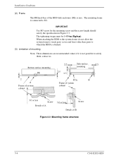
Installation Conditions (2) Frame The MR head bias of mounting Note) These dimensions are recommended values; IMPORTANT Use M3 screw for the mounting screw and the screw length should satisfy the specification in Figure 3.3. When attaching the HDD to the system frame, do not allow the system frame to touch parts (cover and base) other than parts to which...
Installation Conditions (2) Frame The MR head bias of mounting Note) These dimensions are recommended values; IMPORTANT Use M3 screw for the mounting screw and the screw length should satisfy the specification in Figure 3.3. When attaching the HDD to the system frame, do not allow the system frame to touch parts (cover and base) other than parts to which...
Manual/User Guide
Page 5
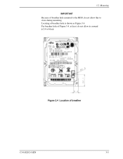
3.2 Mounting IMPORTANT Because of breather C141-E202-01EN 3-5 Figure 3.4 Location of breather hole mounted to the HDD, do not allow this to block. For breather hole of breather hole is shown as Figure 3.4. Locating of Figure 3.4, at least, do not allow its around φ 2.4 to close during mounting.
3.2 Mounting IMPORTANT Because of breather C141-E202-01EN 3-5 Figure 3.4 Location of breather hole mounted to the HDD, do not allow this to block. For breather hole of breather hole is shown as Figure 3.4. Locating of Figure 3.4, at least, do not allow its around φ 2.4 to close during mounting.
Manual/User Guide
Page 6
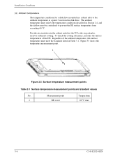
Installation Conditions (4) Ambient temperature The temperature conditions for a disk drive mounted in a cabinet refer to prevent the DE surface temperature from the disk drive. Regardless of the DE. Measurement point Temperature 1 DE cover 60 °C max 3-6 C141-E202-01EN Provide air circulation in the cabinet such that the PCA side, in Table 3.1. To check the cooling efficiency, measure the surface temperatures of...
Installation Conditions (4) Ambient temperature The temperature conditions for a disk drive mounted in a cabinet refer to prevent the DE surface temperature from the disk drive. Regardless of the DE. Measurement point Temperature 1 DE cover 60 °C max 3-6 C141-E202-01EN Provide air circulation in the cabinet such that the PCA side, in Table 3.1. To check the cooling efficiency, measure the surface temperatures of...
Manual/User Guide
Page 7
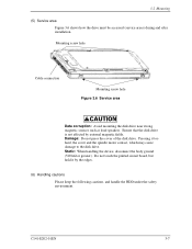
... hole Cable connection Mounting screw hole Figure 3.6 Service area Data corruption: Avoid mounting the disk drive near strong magnetic sources such as loud speakers. Pressing it by external magnetic fields. Damage: Do not press the cover of the disk drive. 3.2 Mounting (5) Service area Figure 3.6 shows how the drive must be accessed (service areas) during and after installation. C141-E202-01EN 3-7 Ensure that the disk drive is...
... hole Cable connection Mounting screw hole Figure 3.6 Service area Data corruption: Avoid mounting the disk drive near strong magnetic sources such as loud speakers. Pressing it by external magnetic fields. Damage: Do not press the cover of the disk drive. 3.2 Mounting (5) Service area Figure 3.6 shows how the drive must be accessed (service areas) during and after installation. C141-E202-01EN 3-7 Ensure that the disk drive is...
Manual/User Guide
Page 8
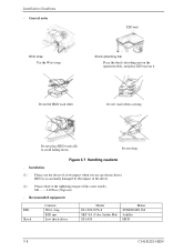
General notes Wrist strap Use the Wrist strap. ESD mat Shock absorbing mat Place the shock absorbing mat on the operation table, and place ESD mat on it. Recommended equipments ESD Shock Contents Wrist strap ESD mat Low shock driver Model JX-1200-3056-8 SKY-...HDD each other. Figure 3.7 Handling cautions - HDD is occasionally damaged by the impact of the driver. (2) Please observe the tightening torque of a low impact when you use an electric driver. M3 0.49N·m (5 kgf·cm). - Installation (1) Please use the driver of the screw strictly. Do not place HDD ...
General notes Wrist strap Use the Wrist strap. ESD mat Shock absorbing mat Place the shock absorbing mat on the operation table, and place ESD mat on it. Recommended equipments ESD Shock Contents Wrist strap ESD mat Low shock driver Model JX-1200-3056-8 SKY-...HDD each other. Figure 3.7 Handling cautions - HDD is occasionally damaged by the impact of the driver. (2) Please observe the tightening torque of a low impact when you use an electric driver. M3 0.49N·m (5 kgf·cm). - Installation (1) Please use the driver of the screw strictly. Do not place HDD ...
Manual/User Guide
Page 9
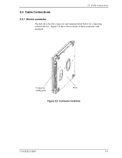
Connector, PCA setting pins Figure 3.8 Connector locations C141-E202-01EN 3-9 Figure 3.8 shows the locations of these connectors and terminals. 3.3 Cable Connections 3.3 Cable Connections 3.3.1 Device connector The disk drive has the connectors and terminals listed below for connecting external devices.
Connector, PCA setting pins Figure 3.8 Connector locations C141-E202-01EN 3-9 Figure 3.8 shows the locations of these connectors and terminals. 3.3 Cable Connections 3.3 Cable Connections 3.3.1 Device connector The disk drive has the connectors and terminals listed below for connecting external devices.
Manual/User Guide
Page 10
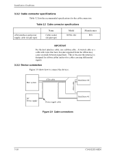
... ATA-cable Disk Drive #0 ATA-cable DC Power supply Power supply cable Disk Drive #1 Figure 3.9 Cable connections 3-10 C141-E202-01EN A twisted cable or a cable with wires that have become separated from the ribbon may cause crosstalk between signal lines. This is because the interface is designed for ribbon cables and not for the cable connectors. Table 3.2 Cable connector specifications ATA interface and power supply cable (44-pin type) Name Cable socket (44-pin type) Model 89361-144 Manufacturer FCI IMPORTANT For the host interface cable, use a ribbon cable...
... ATA-cable Disk Drive #0 ATA-cable DC Power supply Power supply cable Disk Drive #1 Figure 3.9 Cable connections 3-10 C141-E202-01EN A twisted cable or a cable with wires that have become separated from the ribbon may cause crosstalk between signal lines. This is because the interface is designed for ribbon cables and not for the cable connectors. Table 3.2 Cable connector specifications ATA interface and power supply cable (44-pin type) Name Cable socket (44-pin type) Model 89361-144 Manufacturer FCI IMPORTANT For the host interface cable, use a ribbon cable...
Manual/User Guide
Page 11
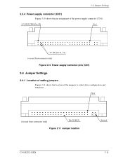
Figure 3.11 Jumper location C141-E202-01EN 3-11 3.4 Jumper Settings 3.3.4 Power supply connector (CN1) Figure 3.10 shows the pin assignment of the jumpers to select drive configuration and functions. Figure 3.10 Power supply connector pins (CN1) 3.4 Jumper Settings 3.4.1 Location of setting jumpers Figure 3.11 shows the location of the power supply connector (CN1).
Figure 3.11 Jumper location C141-E202-01EN 3-11 3.4 Jumper Settings 3.3.4 Power supply connector (CN1) Figure 3.10 shows the pin assignment of the jumpers to select drive configuration and functions. Figure 3.10 Power supply connector pins (CN1) 3.4 Jumper Settings 3.4.1 Location of setting jumpers Figure 3.11 shows the location of the power supply connector (CN1).
Manual/User Guide
Page 12
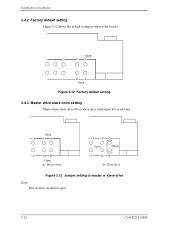
Open Figure 3.12 Factory default setting 3.4.3 Master drive-slave drive setting Master drive (disk drive #0) or slave drive (disk drive #1) is selected. Open 1 CA 2 DB Open (a) Master drive 1 CA Open Short 2 DB (b) Slave drive Figure 3.13 Jumper setting of master or slave drive Note: Pins A and C should be open. 3-12 C141-E202-01EN Installation Conditions 3.4.2 Factory default setting Figure 3.12 shows the default setting position at the factory.
Open Figure 3.12 Factory default setting 3.4.3 Master drive-slave drive setting Master drive (disk drive #0) or slave drive (disk drive #1) is selected. Open 1 CA 2 DB Open (a) Master drive 1 CA Open Short 2 DB (b) Slave drive Figure 3.13 Jumper setting of master or slave drive Note: Pins A and C should be open. 3-12 C141-E202-01EN Installation Conditions 3.4.2 Factory default setting Figure 3.12 shows the default setting position at the factory.
Manual/User Guide
Page 13
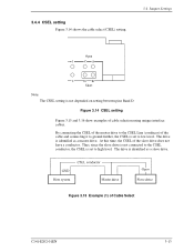
... a slave drive. Figure 3.14 CSEL setting Figure 3.15 and 3.16 show examples of the slave drive does not have a conductor. The drive is identified as a master drive. drive drive Figure 3.15 Example (1) of the cable and connecting it to ground further, the CSEL is set to the CSEL conductor, the CSEL is not depended on setting between pins Band D. 3.4.4 CSEL setting Figure 3.14 shows the cable select (CSEL) setting. 3.4 Jumper Settings Open...
... a slave drive. Figure 3.14 CSEL setting Figure 3.15 and 3.16 show examples of the slave drive does not have a conductor. The drive is identified as a master drive. drive drive Figure 3.15 Example (1) of the cable and connecting it to ground further, the CSEL is set to the CSEL conductor, the CSEL is not depended on setting between pins Band D. 3.4.4 CSEL setting Figure 3.14 shows the cable select (CSEL) setting. 3.4 Jumper Settings Open...
Manual/User Guide
Page 14
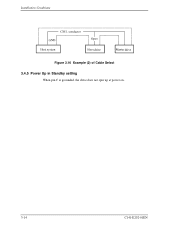
Installation Conditions drive drive Figure 3.16 Example (2) of Cable Select 3.4.5 Power Up in Standby setting When pin C is grounded, the drive does not spin up at power on. 3-14 C141-E202-01EN
Installation Conditions drive drive Figure 3.16 Example (2) of Cable Select 3.4.5 Power Up in Standby setting When pin C is grounded, the drive does not spin up at power on. 3-14 C141-E202-01EN


