Manual/User Guide
Page 9
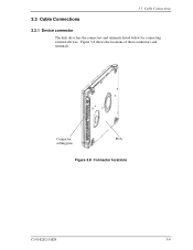
3.3 Cable Connections 3.3 Cable Connections 3.3.1 Device connector The disk drive has the connectors and terminals listed below for connecting external devices. Connector, PCA setting pins Figure 3.8 Connector locations C141-E202-01EN 3-9 Figure 3.8 shows the locations of these connectors and terminals.
3.3 Cable Connections 3.3 Cable Connections 3.3.1 Device connector The disk drive has the connectors and terminals listed below for connecting external devices. Connector, PCA setting pins Figure 3.8 Connector locations C141-E202-01EN 3-9 Figure 3.8 shows the locations of these connectors and terminals.
Manual/User Guide
Page 10
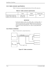
This is because the interface is designed for ribbon cables and not for the cable connectors. Host system ATA-cable Disk Drive #0 ATA-cable DC Power supply Power supply cable Disk Drive #1 Figure 3.9 Cable connections 3-10 C141-E202-01EN A twisted cable or a cable... with wires that have become separated from the ribbon may cause crosstalk between signal lines. Installation Conditions 3.3.2 Cable connector specifications Table 3.2 lists the recommended ...
This is because the interface is designed for ribbon cables and not for the cable connectors. Host system ATA-cable Disk Drive #0 ATA-cable DC Power supply Power supply cable Disk Drive #1 Figure 3.9 Cable connections 3-10 C141-E202-01EN A twisted cable or a cable... with wires that have become separated from the ribbon may cause crosstalk between signal lines. Installation Conditions 3.3.2 Cable connector specifications Table 3.2 lists the recommended ...
Manual/User Guide
Page 11
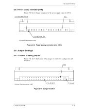
Figure 3.11 Jumper location C141-E202-01EN 3-11 3.4 Jumper Settings 3.3.4 Power supply connector (CN1) Figure 3.10 shows the pin assignment of the jumpers to select drive configuration and functions. Figure 3.10 Power supply connector pins (CN1) 3.4 Jumper Settings 3.4.1 Location of setting jumpers Figure 3.11 shows the location of the power supply connector (CN1).
Figure 3.11 Jumper location C141-E202-01EN 3-11 3.4 Jumper Settings 3.3.4 Power supply connector (CN1) Figure 3.10 shows the pin assignment of the jumpers to select drive configuration and functions. Figure 3.10 Power supply connector pins (CN1) 3.4 Jumper Settings 3.4.1 Location of setting jumpers Figure 3.11 shows the location of the power supply connector (CN1).