
English Manual.
Page 5
... system can operate normally when your CPU is overclocked. It is recommended to the use of your device. ■ If there is turned off before installing or removing CPU, memory, expansion cards or other peripherals. Normally it comes out as a motherboard, CPU or memory. ■ Ensure that the DC power supply is any, when connecting USB, audio, 1394a, RS232 COM, IrDA or S/PDIF cables to your system. Please wear...
... system can operate normally when your CPU is overclocked. It is recommended to the use of your device. ■ If there is turned off before installing or removing CPU, memory, expansion cards or other peripherals. Normally it comes out as a motherboard, CPU or memory. ■ Ensure that the DC power supply is any, when connecting USB, audio, 1394a, RS232 COM, IrDA or S/PDIF cables to your system. Please wear...

English Manual.
Page 6
... Product Specifications 2 Layout...4 Back Panel Connectors 5 Chapter 2 Hardware Install Install the CPU and CPU Cooler 8 Install the Memory 11 Install an Expansion Card 13 Install other Internal Connectors 14 OnBoard Button 18 OnBoard LED 18 OnBoard Debug LED 18 Chapter 3 BIOS Setup Enter BIOS Setup 20 Main Menu 20 System Information 22 Advanced BIOS Features 24 Advanced Chipset Features 29 Boot Configuration Features 30 Power Management Setup 32 PC Health Status 34 Fox Central Control Unit 36 BIOS Security Features 42 Load Optimal Defaults 43 Save & Exit Setup 43...
... Product Specifications 2 Layout...4 Back Panel Connectors 5 Chapter 2 Hardware Install Install the CPU and CPU Cooler 8 Install the Memory 11 Install an Expansion Card 13 Install other Internal Connectors 14 OnBoard Button 18 OnBoard LED 18 OnBoard Debug LED 18 Chapter 3 BIOS Setup Enter BIOS Setup 20 Main Menu 20 System Information 22 Advanced BIOS Features 24 Advanced Chipset Features 29 Boot Configuration Features 30 Power Management Setup 32 PC Health Status 34 Fox Central Control Unit 36 BIOS Security Features 42 Load Optimal Defaults 43 Save & Exit Setup 43...
English Manual.
Page 9
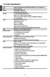
... 2 onboard USB headers supporting 4 extra ports) Supports USB 2.0 protocol up to 480Mb/s Internal Connectors 1 x 24-pin ATX main power connector 1 x 8-pin ATX 12V power connector 1 x IDE connector (Controlled by Jmicron363) 1 x CPU fan header (4-pin) 3 x System fan header (3-pin) 2 x Serial-Attached SCSI Connectors (Controlled by Marvell 88SE6320B1) 1 x HDA Header 1 x 1394a connector 2 x USB 2.0 connectors (supporting 4 x USB devices) 6 x SATA connectors(Controlled by ICH10R) 1 x Front Panel connector 1 x IrDA connector 1 x Chassis intrusion alarm header 1 x Speaker...
... 2 onboard USB headers supporting 4 extra ports) Supports USB 2.0 protocol up to 480Mb/s Internal Connectors 1 x 24-pin ATX main power connector 1 x 8-pin ATX 12V power connector 1 x IDE connector (Controlled by Jmicron363) 1 x CPU fan header (4-pin) 3 x System fan header (3-pin) 2 x Serial-Attached SCSI Connectors (Controlled by Marvell 88SE6320B1) 1 x HDA Header 1 x 1394a connector 2 x USB 2.0 connectors (supporting 4 x USB devices) 6 x SATA connectors(Controlled by ICH10R) 1 x Front Panel connector 1 x IrDA connector 1 x Chassis intrusion alarm header 1 x Speaker...

English Manual.
Page 20
... slot, and press down on the card are completely inserted into the PCI Express x16 slot. Secure the card's metal bracket to release the card and then pull the card straight up from the chassis back panel. 2. PCI Express x4 PCI Express x16 PCI Express x8 PCI Follow the steps below to make any required BIOS changes for your computer. CAUTION 2 2-3 Install an Expansion Card ! ■ Make sure the motherboard supports the expansion card...
... slot, and press down on the card are completely inserted into the PCI Express x16 slot. Secure the card's metal bracket to release the card and then pull the card straight up from the chassis back panel. 2. PCI Express x4 PCI Express x16 PCI Express x8 PCI Follow the steps below to make any required BIOS changes for your computer. CAUTION 2 2-3 Install an Expansion Card ! ■ Make sure the motherboard supports the expansion card...

English Manual.
Page 22
... ATX power connector according to the picture on the front panel. 12 VCC DD+ GND EMPTY VCC DD+ GND NC 9 10 F_USB 1/2 Serial ATA Connectors : SATA_1/2/3/4/5/6 The Serial ATA connector is used to connect with them, user can connect to the eight USB ports on the rear panel, this feature. By connecting through USB cables with SATA Hard Disk or CD devices which support this product also provides two 10-pin USB headers on its motherboard. IrDA Connector...
... ATX power connector according to the picture on the front panel. 12 VCC DD+ GND EMPTY VCC DD+ GND NC 9 10 F_USB 1/2 Serial ATA Connectors : SATA_1/2/3/4/5/6 The Serial ATA connector is used to connect with them, user can connect to the eight USB ports on the rear panel, this feature. By connecting through USB cables with SATA Hard Disk or CD devices which support this product also provides two 10-pin USB headers on its motherboard. IrDA Connector...
English Manual.
Page 23
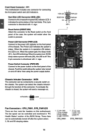
... into sleep mode (S1) , the LED is off rather than using the power supply button. 12 + + HDD-LED - Hard Disk LED Connector (HDD-LED) Connect to the power LED indicator on the front panel of the hard disks. Reset Switch (RESET-SW) Attach the connector to the power button on the front panel of the case; Power Switch Connector (PWR-SW) Connect to the Reset switch on . Push this switch allows the system to a security switch on this connector. It indicates the active status of the chassis. PWR-LED - sign...
... into sleep mode (S1) , the LED is off rather than using the power supply button. 12 + + HDD-LED - Hard Disk LED Connector (HDD-LED) Connect to the power LED indicator on the front panel of the hard disks. Reset Switch (RESET-SW) Attach the connector to the power button on the front panel of the case; Power Switch Connector (PWR-SW) Connect to the Reset switch on . Push this switch allows the system to a security switch on this connector. It indicates the active status of the chassis. PWR-LED - sign...

English Manual.
Page 28
...; Power Management Setup All the items related with Green function features can be setup through this menu. ► PC Health Status This setup enables you need now is heavy, set up through this menu, and there are CPU, memory configuration and Voltage control here. ► BIOS Security Features The Supervisor/User password can be set to optimal default may offer better performance in correct password before boot or access to Setup. ► Load...
...; Power Management Setup All the items related with Green function features can be setup through this menu. ► PC Health Status This setup enables you need now is heavy, set up through this menu, and there are CPU, memory configuration and Voltage control here. ► BIOS Security Features The Supervisor/User password can be set to optimal default may offer better performance in correct password before boot or access to Setup. ► Load...

English Manual.
Page 29
... a BIOS upgrade is depending on how many memory modules were installed in your system before powering on . System Information System Overview Help Item AMIBIOS BIOS Version :08.00.15 BIOS Bulid Date :10/16/08 BIOS ID :853F1P02 Processor Genuine Intel(R) CPU 000 @ 3.20GHz Speed :3200MHz Count :1 Use [ENTER], [TAB] or [SHIFT-TAB] to configure system time. Processor ► CPU Name It displays the current CPU name. ► Speed It displays...
... a BIOS upgrade is depending on how many memory modules were installed in your system before powering on . System Information System Overview Help Item AMIBIOS BIOS Version :08.00.15 BIOS Bulid Date :10/16/08 BIOS ID :853F1P02 Processor Genuine Intel(R) CPU 000 @ 3.20GHz Speed :3200MHz Count :1 Use [ENTER], [TAB] or [SHIFT-TAB] to configure system time. Processor ► CPU Name It displays the current CPU name. ► Speed It displays...

English Manual.
Page 31
...9658; Sixth IDE Slave [Not Detected] Options Disabled Compatible Enhanced IDE Detect Time Out [35] Move Enter:Select +/-/:Value F10:Save ESC:Exit F1:General Help F9:Optimized Defaults ► SATA#1 Configuration SATA#1 are : [IDE]; [RAID]; [AHCI]. [IDE] - Setting values are the SATA ports 1, 2, 3, 4 of the motherboard. IDE Configuration CMOS Setup Utility - This configures the SATA ports to set the operation mode of the SATA ports. When you select the mode of your SATA drives must also support AHCI. [AHCI] - Advanced BIOS Features CMOS Setup Utility - Copyright (C) 1985...
...9658; Sixth IDE Slave [Not Detected] Options Disabled Compatible Enhanced IDE Detect Time Out [35] Move Enter:Select +/-/:Value F10:Save ESC:Exit F1:General Help F9:Optimized Defaults ► SATA#1 Configuration SATA#1 are : [IDE]; [RAID]; [AHCI]. [IDE] - Setting values are the SATA ports 1, 2, 3, 4 of the motherboard. IDE Configuration CMOS Setup Utility - This configures the SATA ports to set the operation mode of the SATA ports. When you select the mode of your SATA drives must also support AHCI. [AHCI] - Advanced BIOS Features CMOS Setup Utility - Copyright (C) 1985...

English Manual.
Page 32
... SATA ports 5,6 of IDE devices. This sub-menu also displays the status of IDE devices. ► Primary/Secondary/Fifth/Sixth IDE Master/Slave, Third/Fourth IDE Master While entering setup, BIOS automatically detects the presence of the motherboard. 3 level interface for a Host Controller for CD/DVD devices in AHCI mode. Please refer to the mapping table in next page. ► Hot Plug (Appears when "Configure SATA#1" is set to[RAID]/[AHCI]) This item is used to set...
... SATA ports 5,6 of IDE devices. This sub-menu also displays the status of IDE devices. ► Primary/Secondary/Fifth/Sixth IDE Master/Slave, Third/Fourth IDE Master While entering setup, BIOS automatically detects the presence of the motherboard. 3 level interface for a Host Controller for CD/DVD devices in AHCI mode. Please refer to the mapping table in next page. ► Hot Plug (Appears when "Configure SATA#1" is set to[RAID]/[AHCI]) This item is used to set...

English Manual.
Page 35
...:Save ESC:Exit F1:General Help F9:Optimized Defaults ► 1394 Controller This item is used to enable or disable the 1394 controller. ► Broadcom5786 Lan Controller This item is used to enable or disable the onboard Broadcom5786 LAN controller. ► Broadcom5786 Lan BOOTROM This item is used to enable or disable the HD Audio Controller. 28 3 OnBoard Device Configuration CMOS Setup Utility - By installing a boot ROM in charge of the ESATA ports on the back panel and the IDE connector on the network.
...:Save ESC:Exit F1:General Help F9:Optimized Defaults ► 1394 Controller This item is used to enable or disable the 1394 controller. ► Broadcom5786 Lan Controller This item is used to enable or disable the onboard Broadcom5786 LAN controller. ► Broadcom5786 Lan BOOTROM This item is used to enable or disable the HD Audio Controller. 28 3 OnBoard Device Configuration CMOS Setup Utility - By installing a boot ROM in charge of the ESATA ports on the back panel and the IDE connector on the network.

English Manual.
Page 39
... memory. Control starts from a saved memory image. ► ACPI Suspend Type This item is used for initial boot operations within the BIOS to distinguish whether or not the boot is going to wake from the processor's reset vector after Power Fail [Power Off] 3 Move Enter:Select +/-/:Value F10:Save ESC:Exit F1:General Help F9:Optimized Defaults ACPI (Advanced Configuration and Power Interface) is lost in the "soft" off all devices...
... memory. Control starts from a saved memory image. ► ACPI Suspend Type This item is used for initial boot operations within the BIOS to distinguish whether or not the boot is going to wake from the processor's reset vector after Power Fail [Power Off] 3 Move Enter:Select +/-/:Value F10:Save ESC:Exit F1:General Help F9:Optimized Defaults ACPI (Advanced Configuration and Power Interface) is lost in the "soft" off all devices...
English Manual.
Page 44
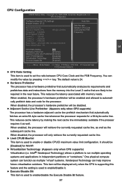
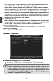
... Technology) allows a platform to set the ratio between CPU Core Genuine Intel(R) CPU 000 @ 3.20GHz Clock and the FSB Frequency :3.20GHz Frequency. The default value is used to enable/disable it as well. When enabled, the processor will be [Disabled] for a 64-byte cache line. One physical compute system can help improve future virtualization solutions. CPU Configuration CMOS Setup Utility - It should be displayed only when the CPU is supporting this feature and the setting...
... Technology) allows a platform to set the ratio between CPU Core Genuine Intel(R) CPU 000 @ 3.20GHz Clock and the FSB Frequency :3.20GHz Frequency. The default value is used to enable/disable it as well. When enabled, the processor will be [Disabled] for a 64-byte cache line. One physical compute system can help improve future virtualization solutions. CPU Configuration CMOS Setup Utility - It should be displayed only when the CPU is supporting this feature and the setting...
English Manual.
Page 45
... Limit Setting [Auto] C1 Auto Demotion [Enabled] C3 Auto Demotion [Enabled] Move Enter:Select +/-/:Value F10:Save ESC:Exit F1:General Help F9:Optimized Defaults ► EIST Function (Appears only when CPU supports) You can free IT resources for more information. 38 3 CAUTION Intel's Execute Disable Bit functionality can halt worm attacks, reducing the need for virus-related repairs. It will be met, including CPU, chipset, motherboard, BIOS...
... Limit Setting [Auto] C1 Auto Demotion [Enabled] C3 Auto Demotion [Enabled] Move Enter:Select +/-/:Value F10:Save ESC:Exit F1:General Help F9:Optimized Defaults ► EIST Function (Appears only when CPU supports) You can free IT resources for more information. 38 3 CAUTION Intel's Execute Disable Bit functionality can halt worm attacks, reducing the need for virus-related repairs. It will be met, including CPU, chipset, motherboard, BIOS...

English Manual.
Page 46
... autodemote information. ► C3 Auto Demotion When enable, CPU will appear: ► DRAM Frequency This item is used to select memory frequency. ► Intel(R) C-STATE Tech This item is used to select the uncore frequency. C-State means CPU idle is part of this item will impact the memory sizing behavior. [Auto]: BIOS will select the frequency automatically. Intel Extreme Memory Profile specification is set "Performance Tuning Mode" to C1 based on...
... autodemote information. ► C3 Auto Demotion When enable, CPU will appear: ► DRAM Frequency This item is used to select memory frequency. ► Intel(R) C-STATE Tech This item is used to select the uncore frequency. C-State means CPU idle is part of this item will impact the memory sizing behavior. [Auto]: BIOS will select the frequency automatically. Intel Extreme Memory Profile specification is set "Performance Tuning Mode" to C1 based on...

English Manual.
Page 49
... user password optionally. ► Change User Password This item is used to enable/disable boot sector virus protection. Enter New Password : Enter New Password : 42 BIOS Security Features Security Settings Help Item Supervisor Password :Not Installed Install or Change the User Password :Not Installed password. ► Change Supervisor Password [Press Enter] ► Change User Password [Press Enter] Boot Sector Virus Protection [Disabled] Move Enter:Select +/-/:Value F10:Save ESC:Exit F1:General Help F9:Optimized Defaults ► Change...
... user password optionally. ► Change User Password This item is used to enable/disable boot sector virus protection. Enter New Password : Enter New Password : 42 BIOS Security Features Security Settings Help Item Supervisor Password :Not Installed Install or Change the User Password :Not Installed password. ► Change Supervisor Password [Press Enter] ► Change User Password [Press Enter] Boot Sector Virus Protection [Disabled] Move Enter:Select +/-/:Value F10:Save ESC:Exit F1:General Help F9:Optimized Defaults ► Change...

English Manual.
Page 52
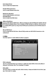
... manually. 45 45 CAUTION You need to install all the other drivers except "Intel RAID Driver". 4 Utility CD introduction This motherboard comes with , simply insert the CD into your motherboard. The CD will automatically run and display the main menu on the screen. 1. After installing "Intel Chipset Driver", you can click "One Click Setup" to restart your computer after finishing all the necessary drivers for your CD drive...
... manually. 45 45 CAUTION You need to install all the other drivers except "Intel RAID Driver". 4 Utility CD introduction This motherboard comes with , simply insert the CD into your motherboard. The CD will automatically run and display the main menu on the screen. 1. After installing "Intel Chipset Driver", you can click "One Click Setup" to restart your computer after finishing all the necessary drivers for your CD drive...
English Manual.
Page 53
... by using onboard SATA ports (controlled by Intel ICH10R) instead of RAID interface on the motherboard. 2. JMicron Raid Driver Use it to install Realtek Audio driver. Realtek HDA Audio Driver Use it to install JMicron RAID driver. 4 Intel chipset Driver Use it to install Intel RAID driver. Marvell SAS provides two SAS SATA Connectors on JMircon, we recommend you to install Intel chipset driver. See "Fox LiveUpdate" for details. 46 46 Intel Raid Driver Use it to backup or update the system BIOS, drivers and utilities in Windows...
... by using onboard SATA ports (controlled by Intel ICH10R) instead of RAID interface on the motherboard. 2. JMicron Raid Driver Use it to install Realtek Audio driver. Realtek HDA Audio Driver Use it to install JMicron RAID driver. 4 Intel chipset Driver Use it to install Intel RAID driver. Marvell SAS provides two SAS SATA Connectors on JMircon, we recommend you to install Intel chipset driver. See "Fox LiveUpdate" for details. 46 46 Intel Raid Driver Use it to backup or update the system BIOS, drivers and utilities in Windows...

English Manual.
Page 108
...keeps loading files until the next screen displays. CAUTION 5-4 Install a New Windows XP ! Set the "1st Boot Device" to enter BIOS Setup during POST. 2. Boot Device Priority Boot Device Priority Help Item 1st Boot Device [CD/DVD:SS-DVD-ROM] ] 2nd Boot Device [HDD:6M-HDS728080PL] Specify the boot sequence from the available devices. A device enclosed in parenthesis has been disabled in BIOS to either AHCI or RAID, you set the SATA Mode in the corresponding type menu. Press to "CD/DVD ROM", save changes and exit the BIOS setup...
...keeps loading files until the next screen displays. CAUTION 5-4 Install a New Windows XP ! Set the "1st Boot Device" to enter BIOS Setup during POST. 2. Boot Device Priority Boot Device Priority Help Item 1st Boot Device [CD/DVD:SS-DVD-ROM] ] 2nd Boot Device [HDD:6M-HDS728080PL] Specify the boot sequence from the available devices. A device enclosed in parenthesis has been disabled in BIOS to either AHCI or RAID, you set the SATA Mode in the corresponding type menu. Press to "CD/DVD ROM", save changes and exit the BIOS setup...

English Manual.
Page 109
... manufacturer-supplied hardware support disk into you to insert the RAID driver diskette into Drive A: * Press ENTER when ready ENTER=Continue ESC=Cancel F3=Exit 102 Windows Setup Setup could not determine the type of one or more mass storage devices installed in your system, the following mass storage device(s): * To specify additional SCSI adapters, CD-ROM drivers, or special disk controllers for use with Windows, press ENTER. Currently, Setup will ask you floppy drive. After some files...
... manufacturer-supplied hardware support disk into you to insert the RAID driver diskette into Drive A: * Press ENTER when ready ENTER=Continue ESC=Cancel F3=Exit 102 Windows Setup Setup could not determine the type of one or more mass storage devices installed in your system, the following mass storage device(s): * To specify additional SCSI adapters, CD-ROM drivers, or special disk controllers for use with Windows, press ENTER. Currently, Setup will ask you floppy drive. After some files...


