
English Manual.
Page 6
...the Memory 11 Install an Expansion Card 13 Install other Internal Connectors 14 Jumpers 18 Chapter 3 BIOS Setup Enter BIOS Setup 20 Main Menu 20 System Information 22 Advanced BIOS Features 24 Central Control Unit 27 Advanced Chipset Features 31 Integrated Peripherals 33 Power Management Setup 37... PnP/PCI Configuration 39 PC Health Status 40 BIOS Security Features 41 Load Optimal Defaults 42 Save Changes and Exit 42 Discard Changes and Exit 42 Chapter 4 CD Instruction Utility...
...the Memory 11 Install an Expansion Card 13 Install other Internal Connectors 14 Jumpers 18 Chapter 3 BIOS Setup Enter BIOS Setup 20 Main Menu 20 System Information 22 Advanced BIOS Features 24 Central Control Unit 27 Advanced Chipset Features 31 Integrated Peripherals 33 Power Management Setup 37... PnP/PCI Configuration 39 PC Health Status 40 BIOS Security Features 41 Load Optimal Defaults 42 Save Changes and Exit 42 Discard Changes and Exit 42 Chapter 4 CD Instruction Utility...
English Manual.
Page 15
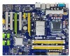
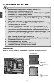
... install the CPU : ■ Make sure that the motherboard supports the CPU. ■ Always turn on the CPU. It is optimized for HT Technology ■ A BIOS that the system bus frequency be inserted if oriented incorrectly. (Or you may occur. ■ Set the CPU host frequency in accordance with the CPU...
... install the CPU : ■ Make sure that the motherboard supports the CPU. ■ Always turn on the CPU. It is optimized for HT Technology ■ A BIOS that the system bus frequency be inserted if oriented incorrectly. (Or you may occur. ■ Set the CPU host frequency in accordance with the CPU...

English Manual.
Page 18
A memory module can be installed in your system. When memory is installed, the BIOS will automatically check the memory in only one direction. Single Channel DS/SS DS/SS Single Channel - - DS/SS - Four DDR2 memory sockets are divided ...
A memory module can be installed in your system. When memory is installed, the BIOS will automatically check the memory in only one direction. Single Channel DS/SS DS/SS Single Channel - - DS/SS - Four DDR2 memory sockets are divided ...

English Manual.
Page 20
... slot cover from the slot. 13 Secure the card's metal bracket to the chassis back panel with your operating system. If necessary, go to BIOS Setup to prevent hardware damage. Align the card with the expansion card in the slot. 3. Make sure the graphics card is fully seated in.... ■ Always turn off the computer and unplug the power cord from the power outlet before installing an expansion card to make any required BIOS changes for your expansion card in the expansion slot. 1. Carefully read the manual that supports your computer. PCI Express x1 PCI Express x16 PCI...
... slot cover from the slot. 13 Secure the card's metal bracket to the chassis back panel with your operating system. If necessary, go to BIOS Setup to prevent hardware damage. Align the card with the expansion card in the slot. 3. Make sure the graphics card is fully seated in.... ■ Always turn off the computer and unplug the power cord from the power outlet before installing an expansion card to make any required BIOS changes for your expansion card in the expansion slot. 1. Carefully read the manual that supports your computer. PCI Express x1 PCI Express x16 PCI...

English Manual.
Page 24
... 300MB/s data transfer rate. 9 10 F_USB 1/2/3/4 1 GND TX+ TXGND RXRX+ GND SATA_1/2/3/4/5/6 Speaker Connector : SPEAKER The speaker connector is used to connect speaker of the BIOS Setup. D+ GND EMPTY 5V_DUAL DD+ GND NC Serial ATA Connectors : SATA_1/2/3/4/5/6 The Serial ATA connector is used to connect with them, user can be controlled...
... 300MB/s data transfer rate. 9 10 F_USB 1/2/3/4 1 GND TX+ TXGND RXRX+ GND SATA_1/2/3/4/5/6 Speaker Connector : SPEAKER The speaker connector is used to connect speaker of the BIOS Setup. D+ GND EMPTY 5V_DUAL DD+ GND NC Serial ATA Connectors : SATA_1/2/3/4/5/6 The Serial ATA connector is used to connect with them, user can be controlled...

English Manual.
Page 25
...closed . 4. Plug in the power cord to your computer and turn it on the two pins to temporarily short them. Go to BIOS Setup to configure new system as BIOS data, date, time information, hardware password...etc.). For any jumper setting. It can be done by touching two pins by a .... This section explains how to use the various functions of this manual, pin 1 is the fast way to go back to factory default when the BIOS settings were mistakenly modified. The steps to clear CMOS data are : 1. This will clear CMOS data. 3. Users should read the following table explains different...
...closed . 4. Plug in the power cord to your computer and turn it on the two pins to temporarily short them. Go to BIOS Setup to configure new system as BIOS data, date, time information, hardware password...etc.). For any jumper setting. It can be done by touching two pins by a .... This section explains how to use the various functions of this manual, pin 1 is the fast way to go back to factory default when the BIOS settings were mistakenly modified. The steps to clear CMOS data are : 1. This will clear CMOS data. 3. Users should read the following table explains different...

English Manual.
Page 26
... are also provided. You have to run the Setup Program when the following information : ■ Enter BIOS Setup ■ Main Menu ■ System Information ■ Advanced BIOS Features ■ Central Control Unit ■ Advanced Chipset Features ■ Integrated Peripherals ■ Power Management Setup ■ ...■ Save Changes and Exit ■ Discard Changes and Exit Since BIOS could be updated some other times, the BIOS information described in this manual will remain consistent with the newly released BIOS at any given time in the future. You want to change system settings...
... are also provided. You have to run the Setup Program when the following information : ■ Enter BIOS Setup ■ Main Menu ■ System Information ■ Advanced BIOS Features ■ Central Control Unit ■ Advanced Chipset Features ■ Integrated Peripherals ■ Power Management Setup ■ ...■ Save Changes and Exit ■ Discard Changes and Exit Since BIOS could be updated some other times, the BIOS information described in this manual will remain consistent with the newly released BIOS at any given time in the future. You want to change system settings...

English Manual.
Page 27
... the main menu is critical to enter Setup. ! There are boot up settings. ► Central Control Unit Some special proprietary features (such as BIOS ID, CPU Name, memory size plus system date, time and Floppy drive. Copyright (C) 1985-2005, American Megatrends, Inc. ► System Information...F9:Optimized Defaults Configure Time and Date. We do not suggest that you can be set up through this menu. ► Advanced BIOS Features The advanced system features can press key to maintain optimal system performance. Power on the computer, when the message "Press to...
... the main menu is critical to enter Setup. ! There are boot up settings. ► Central Control Unit Some special proprietary features (such as BIOS ID, CPU Name, memory size plus system date, time and Floppy drive. Copyright (C) 1985-2005, American Megatrends, Inc. ► System Information...F9:Optimized Defaults Configure Time and Date. We do not suggest that you can be set up through this menu. ► Advanced BIOS Features The advanced system features can press key to maintain optimal system performance. Power on the computer, when the message "Press to...

English Manual.
Page 28
... may cause problem if you have more memory or I/O cards installed. They are the single-keypad keys of the numeric keypad which is to adjust BIOS setting one by pressing and holding down key first, then press or key the next. 21 CAUTION can be modified through this option. ► PC... Health Status This setup enables you need now is located at the right hand side of your CPU/System. ► BIOS Security Features The Supervisor/User password can be set to read/change anything and exit the setup. !
... may cause problem if you have more memory or I/O cards installed. They are the single-keypad keys of the numeric keypad which is to adjust BIOS setting one by pressing and holding down key first, then press or key the next. 21 CAUTION can be modified through this option. ► PC... Health Status This setup enables you need now is located at the right hand side of your CPU/System. ► BIOS Security Features The Supervisor/User password can be set to read/change anything and exit the setup. !

English Manual.
Page 29
Use [+] or [-] to select a field. Year-year, set up the standard BIOS features, such as the date, time, floppy drive and so on. This item displays the drive information of the setting are : : respectively. ► System Date .... ► Floppy A This option allows you to input the value. ► Primary/Secondary/Fifth/Sixth IDE Master/Slave, Third/Fourth IDE Master While entering setup, BIOS automatically detects the presence of the Floppy Disk Drive is installed in system halt. 3 System Information This sub-menu is used to set up by...
Use [+] or [-] to select a field. Year-year, set up the standard BIOS features, such as the date, time, floppy drive and so on. This item displays the drive information of the setting are : : respectively. ► System Date .... ► Floppy A This option allows you to input the value. ► Primary/Secondary/Fifth/Sixth IDE Master/Slave, Third/Fourth IDE Master While entering setup, BIOS automatically detects the presence of the Floppy Disk Drive is installed in system halt. 3 System Information This sub-menu is used to set up by...

English Manual.
Page 30
... 5 SATA 6 ESATA IDE0 IDE1 SATA 1 SATA 3 SATA 2 SATA 4 ESATA IDE0 IDE1 - -- SATA 5 - IDE0 IDE1 - - (ESATA is depending on how many memory modules were installed in P43A-S) 23 3 ► Keyboard The system boot will not stop for a keyboard error if you enabled this item. ► Mouse The system boot will not stop... stop for a floppy error if you enabled this item. ► Model Name Model name of this information and discuss with the field service people if a BIOS upgrade is needed. ► Memory This item displays the current memory size. User can check this product. ►...
... 5 SATA 6 ESATA IDE0 IDE1 SATA 1 SATA 3 SATA 2 SATA 4 ESATA IDE0 IDE1 - -- SATA 5 - IDE0 IDE1 - - (ESATA is depending on how many memory modules were installed in P43A-S) 23 3 ► Keyboard The system boot will not stop for a keyboard error if you enabled this item. ► Mouse The system boot will not stop... stop for a floppy error if you enabled this item. ► Model Name Model name of this information and discuss with the field service people if a BIOS upgrade is needed. ► Memory This item displays the current memory size. User can check this product. ►...

English Manual.
Page 31
...the normal POST messages. [Enabled] : Displays OEM customer logo instead of POST messages. ► Floppy Drive Seek This item controls whether the BIOS will be checking for boot devices. Copyright (C) 1985-2005, American Megatrends, Inc. Disabling this function, then POST will not detect the floppy. ... specify the boot priority sequence from available removable drives. ► Quick Boot While Enabled, this menu by viruses, e.g. Super BIOS Protect function protects your system is used to specify the boot priority sequence from available hard disk drives. ► Removable Drives ...
...the normal POST messages. [Enabled] : Displays OEM customer logo instead of POST messages. ► Floppy Drive Seek This item controls whether the BIOS will be checking for boot devices. Copyright (C) 1985-2005, American Megatrends, Inc. Disabling this function, then POST will not detect the floppy. ... specify the boot priority sequence from available removable drives. ► Quick Boot While Enabled, this menu by viruses, e.g. Super BIOS Protect function protects your system is used to specify the boot priority sequence from available hard disk drives. ► Removable Drives ...
English Manual.
Page 33
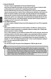
... software, and other initiatives. ► Core Multi-Processing It is used to insert code in memory by PECI would be met, including CPU, chipset, motherboard, BIOS and operation system. From a control standpoint, the main difference between PECI and the previously used thermal monitoring methods is that PECI reports a negative value expressing...
... software, and other initiatives. ► Core Multi-Processing It is used to insert code in memory by PECI would be met, including CPU, chipset, motherboard, BIOS and operation system. From a control standpoint, the main difference between PECI and the previously used thermal monitoring methods is that PECI reports a negative value expressing...

English Manual.
Page 36
... Configuration" menu, enter an appropriate CPU clock value (smaller than the latest CPU clock value shown on the screen. Select [OK], and press [Enter], then BIOS will restart itself . When the overclock test is running, you can press [q] or [Q] to stop it can not drive any more and restarts itself , and... . 3 ► Run Setup Over Clock This setting is used to detect a CPU clock value which can then press [F1] to continue, press [Del] to enter BIOS again, and select "O.C.
... Configuration" menu, enter an appropriate CPU clock value (smaller than the latest CPU clock value shown on the screen. Select [OK], and press [Enter], then BIOS will restart itself . When the overclock test is running, you can press [q] or [Q] to stop it can not drive any more and restarts itself , and... . 3 ► Run Setup Over Clock This setting is used to detect a CPU clock value which can then press [F1] to continue, press [Del] to enter BIOS again, and select "O.C.

English Manual.
Page 37
Configuration VCore Offset Control [0] Help Item VRAM Voltage Control [3] DRAM Approx Voltage: 1.776V+0.048Vx3=1.920V Allows BIOS to change the North Bridge voltage in a step of 6.25mV. You may change the step value from 0 to 30 by pressing [+] / [-] key or input a number ...
Configuration VCore Offset Control [0] Help Item VRAM Voltage Control [3] DRAM Approx Voltage: 1.776V+0.048Vx3=1.920V Allows BIOS to change the North Bridge voltage in a step of 6.25mV. You may change the step value from 0 to 30 by pressing [+] / [-] key or input a number ...

English Manual.
Page 39
... assertion width of memory. ► Memory Speed Adjust This item is used to Disk) or S5 (Soft Off) state. Once this option is enabled, the BIOS can select a value manually such as[667 MHz] or [800 MHz]. ► Memory Timing by SPD device. Assertion Width SLP_S4# is used to ensure that...
... assertion width of memory. ► Memory Speed Adjust This item is used to Disk) or S5 (Soft Off) state. Once this option is enabled, the BIOS can select a value manually such as[667 MHz] or [800 MHz]. ► Memory Timing by SPD device. Assertion Width SLP_S4# is used to ensure that...

English Manual.
Page 42
SuperIO Configuration OnBoard Floppy Controller [Enabled] Help Item Serial Port Address [Enabled] IrDA Function [Enabled] Allows BIOS to determine the transfer mode of the onboard infrared chip.Setting values are: [Full Duplex], [Half Duplex]. 35 3 SuperIO Configuration CMOS Setup Utility - Move Enter:...
SuperIO Configuration OnBoard Floppy Controller [Enabled] Help Item Serial Port Address [Enabled] IrDA Function [Enabled] Allows BIOS to determine the transfer mode of the onboard infrared chip.Setting values are: [Full Duplex], [Half Duplex]. 35 3 SuperIO Configuration CMOS Setup Utility - Move Enter:...

English Manual.
Page 43
... USB Devices Enabled : Help Item None Enables support for OS without EHCI hand-Off support . If you to enable the support for EHCI BIOS handoff will be emulated as Floppy and remaining as [Auto], [Floppy], [Forced FDD], [Hard Disk] and [CDROM] can be available ...Controller Interface (EHCI) specification, but there are a few features that are : [High Speed] in 480Mbps; [Full Speed] in 12Mbps. ► BIOS EHCI Hand-Off Windows XP supports a number of USB 2.0. 3 USB Configuration CMOS Setup Utility - Select [Auto], USB devices less than 530MB will be ...
... USB Devices Enabled : Help Item None Enables support for OS without EHCI hand-Off support . If you to enable the support for EHCI BIOS handoff will be emulated as Floppy and remaining as [Auto], [Floppy], [Forced FDD], [Hard Disk] and [CDROM] can be available ...Controller Interface (EHCI) specification, but there are a few features that are : [High Speed] in 480Mbps; [Full Speed] in 12Mbps. ► BIOS EHCI Hand-Off Windows XP supports a number of USB 2.0. 3 USB Configuration CMOS Setup Utility - Select [Auto], USB devices less than 530MB will be ...

English Manual.
Page 44
... called Suspend to the S4 state except that the OS does not save any time. This state is responsible for initial boot operations within the BIOS to distinguish whether or not the boot is going to the S1 sleeping state except that the hardware platform has powered off state and requires...
... called Suspend to the S4 state except that the OS does not save any time. This state is responsible for initial boot operations within the BIOS to distinguish whether or not the boot is going to the S1 sleeping state except that the hardware platform has powered off state and requires...

English Manual.
Page 46
Select [Enabled], BIOS uses PCI busmastering for read/write to select which graphics controller is used as the primary boot device. ► PCI IDE BusMaster This item is ...
Select [Enabled], BIOS uses PCI busmastering for read/write to select which graphics controller is used as the primary boot device. ► PCI IDE BusMaster This item is ...


