
User manual
Page 1
H67M Series Motherboard User's Manual
H67M Series Motherboard User's Manual

User manual
Page 2
...motherboard better, and tells you will help prevent potential negative consequences for the environment and human health, which could otherwise be caused by inappropriate waste handling of this product. More information: If you want more detailed information about our products, please visit Foxconn...this product. P/N: 3A222NM00-000-G Symbol description: ! All images are for reference only, please refer to the physical motherboard for H67M Series motherboard. Warning: indicating a potential risk of hardware damage or physical injury may be treated as household waste. All trade ...
...motherboard better, and tells you will help prevent potential negative consequences for the environment and human health, which could otherwise be caused by inappropriate waste handling of this product. More information: If you want more detailed information about our products, please visit Foxconn...this product. P/N: 3A222NM00-000-G Symbol description: ! All images are for reference only, please refer to the physical motherboard for H67M Series motherboard. Warning: indicating a potential risk of hardware damage or physical injury may be treated as household waste. All trade ...

User manual
Page 3
... information technology equipment ■ EN 61000-3-2/:2000 Electromagnetic compatibility (EMC) Part 3: Limits Section 2: Limits for harmonic current emissions (equipment input current declares that the product Motherboard H67M-S/H67M/H67M-V is in conformity with (reference to the specification under which conformity is declared in accordance with 89/336 EEC-EMC Directive) ■...
... information technology equipment ■ EN 61000-3-2/:2000 Electromagnetic compatibility (EMC) Part 3: Limits Section 2: Limits for harmonic current emissions (equipment input current declares that the product Motherboard H67M-S/H67M/H67M-V is in conformity with (reference to the specification under which conformity is declared in accordance with 89/336 EEC-EMC Directive) ■...

User manual
Page 4
...: Manufacturer: Address: FCC Class B Subassembly Motherboard HON HAI PRECISION INDUSTRY COMPANY LTD 66 , CHUNG SHAN RD., TU-CHENG INDUSTRIAL DISTRICT, TAIPEI HSIEN, TAIWAN, R.O.C. Fullerton, CA 92835 714-738-8868 714-738-8838 Equipment Classification: Type of conformity Trade Name: Model Name: Responsible Party: Address: Telephone: Facsimile: FOXCONN H67M-S/H67M/H67M-V PCE Industry...
...: Manufacturer: Address: FCC Class B Subassembly Motherboard HON HAI PRECISION INDUSTRY COMPANY LTD 66 , CHUNG SHAN RD., TU-CHENG INDUSTRIAL DISTRICT, TAIPEI HSIEN, TAIWAN, R.O.C. Fullerton, CA 92835 714-738-8868 714-738-8838 Equipment Classification: Type of conformity Trade Name: Model Name: Responsible Party: Address: Telephone: Facsimile: FOXCONN H67M-S/H67M/H67M-V PCE Industry...

User manual
Page 5
...wrist strap when handling components such as a spark which will quickly damage your CPU is overclocked. Incorrect connections might damage the motherboard. ■ When handling the motherboard, avoid touching any installation steps or have a problem related to high temperature. Normally it comes out as... procedures to install your computer : ■ It is suggested to select high-quality, certified fans in order to avoid damage to the motherboard and CPU due to the use of your system, we recommend using a 24-pin ATX power supply to get the best performance. ■...
...wrist strap when handling components such as a spark which will quickly damage your CPU is overclocked. Incorrect connections might damage the motherboard. ■ When handling the motherboard, avoid touching any installation steps or have a problem related to high temperature. Normally it comes out as... procedures to install your computer : ■ It is suggested to select high-quality, certified fans in order to avoid damage to the motherboard and CPU due to the use of your system, we recommend using a 24-pin ATX power supply to get the best performance. ■...

User manual
Page 8
This chapter includes the following information: ■ Product Specifications ■ Layout ■ Back Panel Connectors With advanced overclocking capability and a range of connectivity features for today multi-media computing requirements, H67MS/H67M/H67M-V enables you to maximize computing power, providing only what you for break-through performance. Thank you need for buying Foxconn H67M Series motherboard. Foxconn products are engineered to unleash more power from your computer.
This chapter includes the following information: ■ Product Specifications ■ Layout ■ Back Panel Connectors With advanced overclocking capability and a range of connectivity features for today multi-media computing requirements, H67MS/H67M/H67M-V enables you to maximize computing power, providing only what you for break-through performance. Thank you need for buying Foxconn H67M Series motherboard. Foxconn products are engineered to unleash more power from your computer.

User manual
Page 11
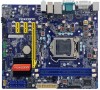
...® H67 16. 24-pin ATX Power Connector 17. LPT Connector 18. COM1 Connector 20. DDR3 DIMM Slots 21. LGA1155 CPU Socket Note : The above motherboard layout is for reference only, please refer to the physical...
...® H67 16. 24-pin ATX Power Connector 17. LPT Connector 18. COM1 Connector 20. DDR3 DIMM Slots 21. LGA1155 CPU Socket Note : The above motherboard layout is for reference only, please refer to the physical...

User manual
Page 14
Please refer to the motherboard layout prior to any installation and read the contents in this chapter carefully. Caution should be exercised during the installation of jumpers. This chapter includes ... the Memory ■ Install an Expansion Card ■ Install other Internal Connectors ■ Jumpers Please visit the following website for more supporting information about your motherboard. This chapter introduces the hardware installation process, including the installation of the CPU, memory, power supply, slots, pin headers and the mounting of these modules...
Please refer to the motherboard layout prior to any installation and read the contents in this chapter carefully. Caution should be exercised during the installation of jumpers. This chapter includes ... the Memory ■ Install an Expansion Card ■ Install other Internal Connectors ■ Jumpers Please visit the following website for more supporting information about your motherboard. This chapter introduces the hardware installation process, including the installation of the CPU, memory, power supply, slots, pin headers and the mounting of these modules...

User manual
Page 15
...Threading Technology System Requirements: (Go to set beyond the standard specifications, please do so according to install the CPU : ■ Make sure that the motherboard supports the CPU. ■ Always turn on the CPU. LGA1155 CPU Socket Alignment Key Pin-1 corner of the CPU Socket Notch LGA1155 CPU Pin-1 ...specifications. The CPU cannot be set the frequency beyond hardware specifications since it enabled Install the CPU Locate the alignment keys on the motherboard CPU socket and the notches on the computer if the CPU cooler is optimized for the peripherals.
...Threading Technology System Requirements: (Go to set beyond the standard specifications, please do so according to install the CPU : ■ Make sure that the motherboard supports the CPU. ■ Always turn on the CPU. LGA1155 CPU Socket Alignment Key Pin-1 corner of the CPU Socket Notch LGA1155 CPU Pin-1 ...specifications. The CPU cannot be set the frequency beyond hardware specifications since it enabled Install the CPU Locate the alignment keys on the motherboard CPU socket and the notches on the computer if the CPU cooler is optimized for the peripherals.

User manual
Page 17
...CPU. Use extreme care when removing the CPU cooler because the thermal grease may damage the CPU. 10 10 Check the solder side of the motherboard, the push pin should be fastened on the surface of CPU. 2. Attach the 4-wire CPU cooler connector to the CPU FAN header on the... motherboard. 2 CAUTION 1. That's it. 3. Install the CPU Cooler Follow the steps below to correctly install the CPU cooler on the motherboard . 3 2 1 Release bolts of CPU cooler from the top, and the bolts will be fixed...
...CPU. Use extreme care when removing the CPU cooler because the thermal grease may damage the CPU. 10 10 Check the solder side of the motherboard, the push pin should be fastened on the surface of CPU. 2. Attach the 4-wire CPU cooler connector to the CPU FAN header on the... motherboard. 2 CAUTION 1. That's it. 3. Install the CPU Cooler Follow the steps below to correctly install the CPU cooler on the motherboard . 3 2 1 Release bolts of CPU cooler from the top, and the bolts will be fixed...

User manual
Page 18
...and chips be installed in only one direction. DS/SS Dual Channel DS/SS - - DS/SS DS/SS Dual Channel - For this motherboard, DIMM(1,2), DIMM(3,4) are : Single Channel DIMM1 DS/SS DIMM2 - Read the following guidelines before installing the memory to identify the sequence ...of DIMM modules are two pairs of DIMM channel, you begin to insert the memory, switch the direction. 2 Dual Channel Memory Configuration This motherboard provides Four DDR3 memory sockets and supports Dual Channel Technology. DIMM4 - Single Channel - - DS/SS Dual Channel DS/SS - Dual Channel...
...and chips be installed in only one direction. DS/SS Dual Channel DS/SS - - DS/SS DS/SS Dual Channel - For this motherboard, DIMM(1,2), DIMM(3,4) are : Single Channel DIMM1 DS/SS DIMM2 - Read the following guidelines before installing the memory to identify the sequence ...of DIMM modules are two pairs of DIMM channel, you begin to insert the memory, switch the direction. 2 Dual Channel Memory Configuration This motherboard provides Four DDR3 memory sockets and supports Dual Channel Technology. DIMM4 - Single Channel - - DS/SS Dual Channel DS/SS - Dual Channel...

User manual
Page 19
... sure to turn off the computer and unplug the power cord from the power outlet to prevent damage to correctly install your fingers on this motherboard. Step 1: Spread the clips at both sides separated by a notch in one direction. Be sure to install DDR3 DIMMs on top edge of the socket...
... sure to turn off the computer and unplug the power cord from the power outlet to prevent damage to correctly install your fingers on this motherboard. Step 1: Spread the clips at both sides separated by a notch in one direction. Be sure to install DDR3 DIMMs on top edge of the socket...

User manual
Page 20
CAUTION 2 2-3 Install an Expansion Card ! ■ Make sure the motherboard supports the expansion card. Carefully read the manual that supports your computer. Remove the metal slot cover from the slot. 13 13 Align the card ...
CAUTION 2 2-3 Install an Expansion Card ! ■ Make sure the motherboard supports the expansion card. Carefully read the manual that supports your computer. Remove the metal slot cover from the slot. 13 13 Align the card ...

User manual
Page 21
... the power supply cable and pins are using a 24-pin power supply. 2 CAUTION 2-4 Install other Internal Connectors Power Connectors This motherboard uses an ATX power supply. Firmly plug the power supply cable into the connector and make sure all the devices have been installed ... before applying the power supply. 24-pin ATX Power Connector : PWR1 PWR1 is secure. We recommend you are properly aligned with the connector on the motherboard. Pin # Definition Pin # Definition 1 3.3V 13 3.3V 2 3.3V 14 -12V 3 GND 15 GND 4 +5V 16 PS_ON(Soft On/Off) 5 GND 17 GND...
... the power supply cable and pins are using a 24-pin power supply. 2 CAUTION 2-4 Install other Internal Connectors Power Connectors This motherboard uses an ATX power supply. Firmly plug the power supply cable into the connector and make sure all the devices have been installed ... before applying the power supply. 24-pin ATX Power Connector : PWR1 PWR1 is secure. We recommend you are properly aligned with the connector on the motherboard. Pin # Definition Pin # Definition 1 3.3V 13 3.3V 2 3.3V 14 -12V 3 GND 15 GND 4 +5V 16 PS_ON(Soft On/Off) 5 GND 17 GND...

User manual
Page 22
.../DVD-ROM drive through USB cables with SATA Hard Disk or CD devices which support this product also provides 10-pin USB headers on its motherboard. D- The SATA_3/4/5/6 allows up to 300MB/s data transfer rate, the SATA_1/2 support SATA 3.0 specification, and allows up to the USB ports on the front panel...
.../DVD-ROM drive through USB cables with SATA Hard Disk or CD devices which support this product also provides 10-pin USB headers on its motherboard. D- The SATA_3/4/5/6 allows up to 300MB/s data transfer rate, the SATA_1/2 support SATA 3.0 specification, and allows up to the USB ports on the front panel...

User manual
Page 23
To utilize this switch allows the system to the power button on this motherboard. The fan speed can be controlled and monitored in " Health" section of the hard disks. RESET-SW PWR-SW NC EMPTY 9 10 FP1 12 LCLK ...) provides the ability to the PC to run applications more secure and to the chassis front panel IDE indicator LED. 2 Front Panel Connector : FP1 This motherboard includes one connector for connecting the front panel switch and LED Indicators. This 2-pin connector is directional with +/- Reset Switch (RESET-SW) Attach the connector...
To utilize this switch allows the system to the power button on this motherboard. The fan speed can be controlled and monitored in " Health" section of the hard disks. RESET-SW PWR-SW NC EMPTY 9 10 FP1 12 LCLK ...) provides the ability to the PC to run applications more secure and to the chassis front panel IDE indicator LED. 2 Front Panel Connector : FP1 This motherboard includes one connector for connecting the front panel switch and LED Indicators. This 2-pin connector is directional with +/- Reset Switch (RESET-SW) Attach the connector...

User manual
Page 24
... one end to connect with the external RS232 device and another end with 10-pin female connector to connect with COM1 connector in the motherboard. Strobe Data it [0] Data it [1] Data it [2] Data it [3] Data it [4] Data it [5] Data it [6] Data it 's default interrupt request and the parallel port has ...
... one end to connect with the external RS232 device and another end with 10-pin female connector to connect with COM1 connector in the motherboard. Strobe Data it [0] Data it [1] Data it [2] Data it [3] Data it [4] Data it [5] Data it [6] Data it 's default interrupt request and the parallel port has ...

User manual
Page 25
... Pin 3 closed . 4. etc.). Go to BIOS Setup to it. It can prevent hazardous ESD (Electrical Static Discharge) problem. Plug in this motherboard, pin 1 can be done by touching two pins by changing the jumper settings. Remove jumper cap from the power outlet. 2. This will clear ... BIOS data, date, time information, hardware password... For any jumper setting. This section explains how to use the various functions of this motherboard to your computer and turn it onto pins 1-2 to temporarily short them . 2 2-5 Jumpers For some features needed, users can change ...
... Pin 3 closed . 4. etc.). Go to BIOS Setup to it. It can prevent hazardous ESD (Electrical Static Discharge) problem. Plug in this motherboard, pin 1 can be done by touching two pins by changing the jumper settings. Remove jumper cap from the power outlet. 2. This will clear ... BIOS data, date, time information, hardware password... For any jumper setting. This section explains how to use the various functions of this motherboard to your computer and turn it onto pins 1-2 to temporarily short them . 2 2-5 Jumpers For some features needed, users can change ...

User manual
Page 31
... Enter: Select +/-: Change Opt. The voltage can not show TPM. O.S. If you want to support TPM, first you need to install a TPM device on the motherboard and set this item to [Enabled], then save changing and reset your computer, otherwise the operation system can be incremented from +12.5mV to +500...
... Enter: Select +/-: Change Opt. The voltage can not show TPM. O.S. If you want to support TPM, first you need to install a TPM device on the motherboard and set this item to [Enabled], then save changing and reset your computer, otherwise the operation system can be incremented from +12.5mV to +500...

User manual
Page 33
... the "Turbo Mode" is for 1/2/3/4 core active. 0 means using the factory configured value. 26 There are some system requirements must be met, including CPU, chipset, motherboard, BIOS and operation system. C opyright (C) 2010 American Megatrends, Inc. Advanced EIST Turbo Mode 1 Core Ratio Limit 2 Core Ratio Limit 3 Core Ratio Limit 4 Core Ratio Limit...
... the "Turbo Mode" is for 1/2/3/4 core active. 0 means using the factory configured value. 26 There are some system requirements must be met, including CPU, chipset, motherboard, BIOS and operation system. C opyright (C) 2010 American Megatrends, Inc. Advanced EIST Turbo Mode 1 Core Ratio Limit 2 Core Ratio Limit 3 Core Ratio Limit 4 Core Ratio Limit...


