
User manual
Page 20
... card. Installing and Removing a PCI Express x16 Graphics Card : • Installing a Graphics Card: Gently insert the graphics card into the slot. 4. After installing all expansion cards, replace the chassis cover. 6. PCI Express x16 PCI Express x1 Follow the steps below to release the card and then pull the card straight up from the chassis back panel. 2. Align the card with the expansion card in the expansion slot. 1. Carefully read the manual that supports your computer. Remove the metal slot cover from the slot...
... card. Installing and Removing a PCI Express x16 Graphics Card : • Installing a Graphics Card: Gently insert the graphics card into the slot. 4. After installing all expansion cards, replace the chassis cover. 6. PCI Express x16 PCI Express x1 Follow the steps below to release the card and then pull the card straight up from the chassis back panel. 2. Align the card with the expansion card in the expansion slot. 1. Carefully read the manual that supports your computer. Remove the metal slot cover from the slot...
User manual
Page 23
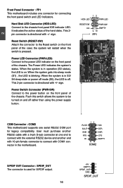
... in S3/ S4 sleep state or power off rather than using the power supply button. 12 + + HDD-LED - Reset Switch (RESET-SW) Attach the connector to the power button on . When the system gets into sleep mode (S1) , the LED is directional with 10-pin female connector to the power LED indicator on the front panel of the hard disks. Push this switch allows the system to the chassis front panel IDE indicator LED. This 2pin connector is blinking; the...
... in S3/ S4 sleep state or power off rather than using the power supply button. 12 + + HDD-LED - Reset Switch (RESET-SW) Attach the connector to the power button on . When the system gets into sleep mode (S1) , the LED is directional with 10-pin female connector to the power LED indicator on the front panel of the hard disks. Push this switch allows the system to the chassis front panel IDE indicator LED. This 2pin connector is blinking; the...
User manual
Page 25
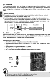
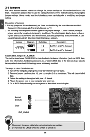
... pins by changing the jumper settings. Users should read the following table explains different types of the jumper settings. For any jumper setting. The following content carefully prior to use the various functions of Jumpers 1. Clear CMOS data is recommended. This will clear CMOS data. 3. Plug in the power cord to store the basic hardware information (such as BIOS data, date, time information, hardware password...etc.). CLR_CMOS ■ Disconnect the power cable...
... pins by changing the jumper settings. Users should read the following table explains different types of the jumper settings. For any jumper setting. The following content carefully prior to use the various functions of Jumpers 1. Clear CMOS data is recommended. This will clear CMOS data. 3. Plug in the power cord to store the basic hardware information (such as BIOS data, date, time information, hardware password...etc.). CLR_CMOS ■ Disconnect the power cable...

User manual
Page 28
.../change you to key in correct password before boot or access to Setup. If you can set up through this menu to prevent unauthorized use of your system loading is explained below: Main It displays the basic system configuration, such as less I /O cards installed. F-Center Some special proprietary features (such as overclocking) can be loaded through this menu. CAUTION 3 Enter BIOS Setup The BIOS is the communication bridge between hardware and software, correctly setting...
.../change you to key in correct password before boot or access to Setup. If you can set up through this menu to prevent unauthorized use of your system loading is explained below: Main It displays the basic system configuration, such as less I /O cards installed. F-Center Some special proprietary features (such as overclocking) can be loaded through this menu. CAUTION 3 Enter BIOS Setup The BIOS is the communication bridge between hardware and software, correctly setting...
User manual
Page 33
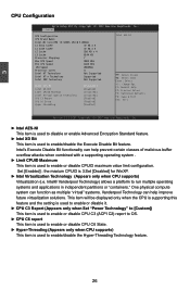
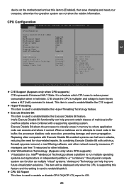
... Cache 6144 KB Processor Stepping 7 Max CPU Speed 2800 MHz Min CPU Speed 1600 MHz CPU Speed 2800MHz Processor Cores 4 Intel HT Technolony Not Supported Intel VT-x Technolony Supported Intel SMX Technolony Not Supported Intel AES-NI Intel XD Bit Limit CPUID Maximum Intel Virtualization Technolony CPU C3 Report CPU C6 State Hyper-threading [Disabled] [Enabled] [Disabled] [Disabled] [Enabled] [Enabled] [Enabled] Intel AES-NI → ←: Select Screen ↑ ↓: Select Item Enter: Select +/-: Change Opt. 3 CPU Configuration Aptio Setup Utility -
... Cache 6144 KB Processor Stepping 7 Max CPU Speed 2800 MHz Min CPU Speed 1600 MHz CPU Speed 2800MHz Processor Cores 4 Intel HT Technolony Not Supported Intel VT-x Technolony Supported Intel SMX Technolony Not Supported Intel AES-NI Intel XD Bit Limit CPUID Maximum Intel Virtualization Technolony CPU C3 Report CPU C6 State Hyper-threading [Disabled] [Enabled] [Disabled] [Disabled] [Enabled] [Enabled] [Enabled] Intel AES-NI → ←: Select Screen ↑ ↓: Select Item Enter: Select +/-: Change Opt. 3 CPU Configuration Aptio Setup Utility -
User manual
Page 40
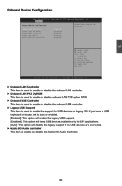
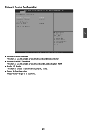
...;: Select Screen ↑ ↓: Select Item Enter: Select +/-: Change Opt. If you have a USB keyboard or mouse, set to enable the support for EFI applications. [Auto]: This option will disable the legacy support if no USB devices are connected. ► Azalia HD Audio controller This item is enable oe disable the Azalia HD Audio Controller. 33 F1: General Help F2: Previous Values F3: Optimized Defaults F4: Save & Exit ESC: Exit Version 2.14.1219. 3 Onboard Device Configuration Aptio Setup Utility...
...;: Select Screen ↑ ↓: Select Item Enter: Select +/-: Change Opt. If you have a USB keyboard or mouse, set to enable the support for EFI applications. [Auto]: This option will disable the legacy support if no USB devices are connected. ► Azalia HD Audio controller This item is enable oe disable the Azalia HD Audio Controller. 33 F1: General Help F2: Previous Values F3: Optimized Defaults F4: Save & Exit ESC: Exit Version 2.14.1219. 3 Onboard Device Configuration Aptio Setup Utility...
User manual
Page 41
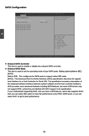
... SATA Configuration Onboard SATA Controller Onboard SATA Mode [Enabled] [Native IDE] SATA Ports Device Names if Present and Enabled. ▶ SATA Port1:Not Present ▶ SATA Port2:Not Present ▶ SATA Port3:Not Present ▶ SATA Port4:Not Present → ←: Select Screen ↑ ↓: Select Item Enter: Select +/-: Change Opt. Setting options:[Native IDE]; [AHCI]. [Native IDE] - F1: General Help F2: Previous Values F3: Optimized Defaults F4: Save & Exit ESC: Exit Version 2.14.1219. This configures the SATA ports to set...
... SATA Configuration Onboard SATA Controller Onboard SATA Mode [Enabled] [Native IDE] SATA Ports Device Names if Present and Enabled. ▶ SATA Port1:Not Present ▶ SATA Port2:Not Present ▶ SATA Port3:Not Present ▶ SATA Port4:Not Present → ←: Select Screen ↑ ↓: Select Item Enter: Select +/-: Change Opt. Setting options:[Native IDE]; [AHCI]. [Native IDE] - F1: General Help F2: Previous Values F3: Optimized Defaults F4: Save & Exit ESC: Exit Version 2.14.1219. This configures the SATA ports to set...
User manual
Page 42
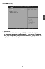
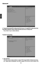
...;: Select Item Enter: Select +/-: Change Opt. Reset of platform is used to decide whether to [Enabled], then save changing and reset your computer, otherwise the operation system can not show TPM. If you want to support TPM, first you need to install a TPM device on the motherboard and set this item to support TPM (Trusted Platform Module) device function. O.S. Default option is [Disabled]. 3 Trusted Computing Aptio Setup Utility - F1...
...;: Select Item Enter: Select +/-: Change Opt. Reset of platform is used to decide whether to [Enabled], then save changing and reset your computer, otherwise the operation system can not show TPM. If you want to support TPM, first you need to install a TPM device on the motherboard and set this item to support TPM (Trusted Platform Module) device function. O.S. Default option is [Disabled]. 3 Trusted Computing Aptio Setup Utility - F1...
User manual
Page 45
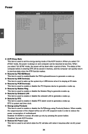
... SUSPEND button is used to enable or disable RTC alarm event to set the energy saving mode of the computer before it entering STR will take with when it is staying at any time. Main F-Center Advanced Boot Power Health Security Save & Exit ACPI Sleep State Resume By PS2 KB/Mouse Resume By USB Device(s) Resume By PCIE Device(s) Resume By Modem Ring Resume By Onboard LAN Resume...
... SUSPEND button is used to enable or disable RTC alarm event to set the energy saving mode of the computer before it entering STR will take with when it is staying at any time. Main F-Center Advanced Boot Power Health Security Save & Exit ACPI Sleep State Resume By PS2 KB/Mouse Resume By USB Device(s) Resume By PCIE Device(s) Resume By Modem Ring Resume By Onboard LAN Resume...
User manual
Page 47
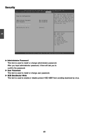
Main F-Center Advanced Boot Power Health SSeeccuurriittyy Save & Exit Security Configuration Administrator Password User Password Administrator Password Not Installed Not Installed Set Administrator Password. If only the Administrator's password is set,then this only limits access to Setup and is only asked for when entering Setup.The password must be 3 to install or change user password. ► HDD BootSector Write This item is used to 20 characters long. Copyright (C) 2012 American Megatrends, Inc. ► Administrator Password This item...
Main F-Center Advanced Boot Power Health SSeeccuurriittyy Save & Exit Security Configuration Administrator Password User Password Administrator Password Not Installed Not Installed Set Administrator Password. If only the Administrator's password is set,then this only limits access to Setup and is only asked for when entering Setup.The password must be 3 to install or change user password. ► HDD BootSector Write This item is used to 20 characters long. Copyright (C) 2012 American Megatrends, Inc. ► Administrator Password This item...
User manual
Page 50
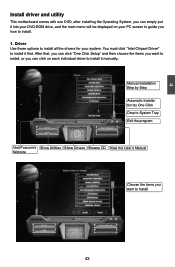
... put it into your DVD-ROM drive, and the main menu will be displayed on each individual driver to install it first. After that, you can click "One Click Setup" and then choose the items you want to install all the drivers for your system. You must click "Intel Chipset Driver" to install it manually. 4 Install driver and utility This motherboard comes with one DVD, after installing the Operating System, you...
... put it into your DVD-ROM drive, and the main menu will be displayed on each individual driver to install it first. After that, you can click "One Click Setup" and then choose the items you want to install all the drivers for your system. You must click "Intel Chipset Driver" to install it manually. 4 Install driver and utility This motherboard comes with one DVD, after installing the Operating System, you...
User manual
Page 9
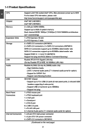
...Specifications 1 CPU Chipset Memory Expansion Slots Storage LAN Audio USB Back Panel Connectors Internal Connectors Support LGA1155 socket Intel® CPU, Max processor power up to 95W For the latest CPU information, please visit: http://www.foxconnsupport.com/cpusupportlist.aspx Intel® H61 (H61MXV) Intel® H67 (H67MXV) 2 x 240-pin DDR3 DIMMs Support up to 8GB of system memory Dual channel DDR3 1800(oc*)/1600(oc*)/1333/1066MHz architecture (oc*: overclocking) 1 x PCI Express x16 slot 2 x PCI Express x1 slots 4 x SATA 2.0 connectors (H61MXV) 2 x SATA 2.0 connectors, 2 x SATA...
...Specifications 1 CPU Chipset Memory Expansion Slots Storage LAN Audio USB Back Panel Connectors Internal Connectors Support LGA1155 socket Intel® CPU, Max processor power up to 95W For the latest CPU information, please visit: http://www.foxconnsupport.com/cpusupportlist.aspx Intel® H61 (H61MXV) Intel® H67 (H67MXV) 2 x 240-pin DDR3 DIMMs Support up to 8GB of system memory Dual channel DDR3 1800(oc*)/1600(oc*)/1333/1066MHz architecture (oc*: overclocking) 1 x PCI Express x16 slot 2 x PCI Express x1 slots 4 x SATA 2.0 connectors (H61MXV) 2 x SATA 2.0 connectors, 2 x SATA...
User manual
Page 20
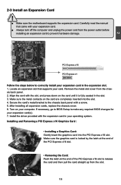
... expansion cards, replace the chassis cover. 6. Turn on the card are completely inserted into the PCI Express x16 slot. Make sure the graphics card is fully seated in the slot. 3. Locate an expansion slot that came with the expansion card in the expansion slot. 1. If necessary, go to BIOS Setup to prevent hardware damage. Carefully read the manual that supports your expansion card(s). 7. Secure the card's metal bracket to the chassis back panel...
... expansion cards, replace the chassis cover. 6. Turn on the card are completely inserted into the PCI Express x16 slot. Make sure the graphics card is fully seated in the slot. 3. Locate an expansion slot that came with the expansion card in the expansion slot. 1. If necessary, go to BIOS Setup to prevent hardware damage. Carefully read the manual that supports your expansion card(s). 7. Secure the card's metal bracket to the chassis back panel...

User manual
Page 23
... front panel of the hard disks. Power LED Connector (PWR-LED) Connect to the Reset switch on the front panel of the chassis. PWR-LED - Hard Disk LED Connector (HDD-LED) Connect to the power button on . the system will restart when the switch is used for S/PDIF output. 16 +5V 1 EMPTY 2 SPDIF_OUT 3 GND 4 SPDIF_OUT sign. 2 Front Panel Connector : FP1 This motherboard includes one serial RS232 COM port for legacy compatibility. When the system is in S3/ S4 sleep state or power off mode...
... front panel of the hard disks. Power LED Connector (PWR-LED) Connect to the Reset switch on the front panel of the chassis. PWR-LED - Hard Disk LED Connector (HDD-LED) Connect to the power button on . the system will restart when the switch is used for S/PDIF output. 16 +5V 1 EMPTY 2 SPDIF_OUT 3 GND 4 SPDIF_OUT sign. 2 Front Panel Connector : FP1 This motherboard includes one serial RS232 COM port for legacy compatibility. When the system is in S3/ S4 sleep state or power off mode...
User manual
Page 25
... password...etc.). The steps to store the basic hardware information (such as "1". 2. The shorting can also be identified by the bold silkscreen next to configure new system as described in this manual, pin 1 is turned on. 18 Normal 1 2 (Default) 3 1 Clear 2 3 WARNING! Jumper Diagram Definition Description 1 1 1 1-2 Set Pin 1 and Pin 2 closed 2-3 Set Pin 2 and Pin 3 closed . 4. 2 2-5 Jumpers For some features needed, users can change the jumper settings on this motherboard to modifying any jumper...
... password...etc.). The steps to store the basic hardware information (such as "1". 2. The shorting can also be identified by the bold silkscreen next to configure new system as described in this manual, pin 1 is turned on. 18 Normal 1 2 (Default) 3 1 Clear 2 3 WARNING! Jumper Diagram Definition Description 1 1 1 1-2 Set Pin 1 and Pin 2 closed 2-3 Set Pin 2 and Pin 3 closed . 4. 2 2-5 Jumpers For some features needed, users can change the jumper settings on this motherboard to modifying any jumper...
User manual
Page 31
... Defaults F4: Save & Exit ESC: Exit Version 2.02.1205. will not show TPM. Default option is required. → ← : Select Screen ↑ ↓ : Select Item Enter: Select +/-: Change Opt. Copyright (C) 2010 American Megatrends, Inc. ► Trusted Computing/CPU Configuration/Performance Tuning/SATA Configuration/Intel IGD SWSCI OpRegion /USB Configuration/Onboard Device Configuration Press to go to relative submenu. 3 Advanced Aptio Setup Utility - C opyright (C) 2010 American Megatrends, Inc. Main Advanced Chipset Boot Power...
... Defaults F4: Save & Exit ESC: Exit Version 2.02.1205. will not show TPM. Default option is required. → ← : Select Screen ↑ ↓ : Select Item Enter: Select +/-: Change Opt. Copyright (C) 2010 American Megatrends, Inc. ► Trusted Computing/CPU Configuration/Performance Tuning/SATA Configuration/Intel IGD SWSCI OpRegion /USB Configuration/Onboard Device Configuration Press to go to relative submenu. 3 Advanced Aptio Setup Utility - C opyright (C) 2010 American Megatrends, Inc. Main Advanced Chipset Boot Power...
User manual
Page 32
Advanced CPU Configuration Genuine Intel(R) CPU 0 @ 2.40GHz EMT64 Supported Max Processor Speed 2400 MHz Min Processor Speed 1600 MHz Processor Speed 2400 MHz CPU ID 206a2 Microcode Revision 26 Processor Cores 2 Intel HT Technology Supported C1E Support Hyper-threading Execute Disable Bit Intel Virtualization Technology CPU C6 Report Package C State limit [Enabled] [Enabled] [Enabled] [Disabled] [Enabled] [No Limit] → ← : Select Screen ↑ ↓ : Select Item Enter: Select +/-: Change Opt. C1E drops the CPU's multiplier and voltage to run ...
Advanced CPU Configuration Genuine Intel(R) CPU 0 @ 2.40GHz EMT64 Supported Max Processor Speed 2400 MHz Min Processor Speed 1600 MHz Processor Speed 2400 MHz CPU ID 206a2 Microcode Revision 26 Processor Cores 2 Intel HT Technology Supported C1E Support Hyper-threading Execute Disable Bit Intel Virtualization Technology CPU C6 Report Package C State limit [Enabled] [Enabled] [Enabled] [Disabled] [Enabled] [No Limit] → ← : Select Screen ↑ ↓ : Select Item Enter: Select +/-: Change Opt. C1E drops the CPU's multiplier and voltage to run ...
User manual
Page 36
... Azalia HD audio. ► Super IO Configuration Press to go to its submenu. 29 C opyright (C) 2010 American Megatrends, Inc. F1: General Help F2: Previous Values F3: Optimized Defaults F4: Save & Exit ESC: Exit Version 2.02.1205. Advanced Onboard Device Configuration Onboard LAN Controller Onboard LAN PXE OpROM [Enabled] [Disabled] Audio Configuration Azalia HD Audio [Enabled] ▶ Super IO Configuration → ← : Select Screen ↑ ↓ : Select Item Enter: Select +/-: Change Opt. 3 Onboard Device Configuration Aptio Setup Utility -
... Azalia HD audio. ► Super IO Configuration Press to go to its submenu. 29 C opyright (C) 2010 American Megatrends, Inc. F1: General Help F2: Previous Values F3: Optimized Defaults F4: Save & Exit ESC: Exit Version 2.02.1205. Advanced Onboard Device Configuration Onboard LAN Controller Onboard LAN PXE OpROM [Enabled] [Disabled] Audio Configuration Azalia HD Audio [Enabled] ▶ Super IO Configuration → ← : Select Screen ↑ ↓ : Select Item Enter: Select +/-: Change Opt. 3 Onboard Device Configuration Aptio Setup Utility -
User manual
Page 48
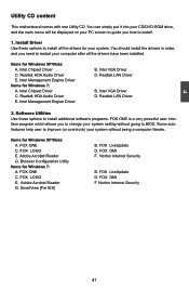
... without going to install. 1. Intel Chipset Driver C. Realtek HDA Audio Driver E. 4 Utility CD content This motherboard comes with one Utility CD. Norton Internet Security 41 Install Driver Use these options to install additional software programs. FOX ONE is a very powerful user interface program which allows you how to BIOS. Realtek HDA Audio Driver E. Intel VGA Driver D. You can simply put it into your CD/DVD-ROM drive, and the main menu will be displayed on your system...
... without going to install. 1. Intel Chipset Driver C. Realtek HDA Audio Driver E. 4 Utility CD content This motherboard comes with one Utility CD. Norton Internet Security 41 Install Driver Use these options to install additional software programs. FOX ONE is a very powerful user interface program which allows you how to BIOS. Realtek HDA Audio Driver E. Intel VGA Driver D. You can simply put it into your CD/DVD-ROM drive, and the main menu will be displayed on your system...
User manual
Page 110
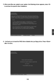
... use with Windows, including those for use with Windows, press ENTER. Press after it is done. Windows Setup Setup could not determine the type of one or more mass storage devices installed in your system, the following mass storage device(s): * To specify additional SCSI adapters, CD-ROM drivers, or special disk controllers for which you have a device support disk from a mass storage device manufacturer, press S. * If you floppy drive. Windows Setup Please insert the disk labeled manufacturer-supplied hardware support disk...
... use with Windows, including those for use with Windows, press ENTER. Press after it is done. Windows Setup Setup could not determine the type of one or more mass storage devices installed in your system, the following mass storage device(s): * To specify additional SCSI adapters, CD-ROM drivers, or special disk controllers for which you have a device support disk from a mass storage device manufacturer, press S. * If you floppy drive. Windows Setup Please insert the disk labeled manufacturer-supplied hardware support disk...


