User manual
Page 1
H61AP Series Motherboard User's Manual
H61AP Series Motherboard User's Manual
User manual
Page 2
... changes. Although the information in this symbol indicates that can help prevent potential negative consequences for specific features. WEEE: The use motherboard better, and tells you how to avoid problems. Caution: indicating a potential risk of this manual may not be treated as ...exist. Version: User's Manual V1.2 for H61AP-S/H61AP motherboard. All trade names are for reference only, please refer to the physical motherboard for the environment and human health, which could otherwise be changed or modified at any time, Foxconn does not obligate itself to inform the user...
... changes. Although the information in this symbol indicates that can help prevent potential negative consequences for specific features. WEEE: The use motherboard better, and tells you how to avoid problems. Caution: indicating a potential risk of this manual may not be treated as ...exist. Version: User's Manual V1.2 for H61AP-S/H61AP motherboard. All trade names are for reference only, please refer to the physical motherboard for the environment and human health, which could otherwise be changed or modified at any time, Foxconn does not obligate itself to inform the user...
User manual
Page 3
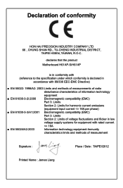
declares that the product Motherboard H61AP-S/H61AP is in conformity with (reference to the specification under which conformity is declared in accordance with 89/336 EEC-EMC Directive) ■ EN 55022: 1998/...
declares that the product Motherboard H61AP-S/H61AP is in conformity with (reference to the specification under which conformity is declared in accordance with 89/336 EEC-EMC Directive) ■ EN 55022: 1998/...
User manual
Page 4
Signature : Date : 2012 Declaration of Product: Manufacturer: Address: FCC Class B Subassembly Motherboard HON HAI PRECISION INDUSTRY COMPANY LTD 66 , CHUNG SHAN RD., TU-CHENG INDUSTRIAL DISTRICT, TAIPEI HSIEN, TAIWAN, R.O.C. Lambert Rd. Operation is subject to comply with ... undesired operation. Fullerton, CA 92835 714-738-8868 714-738-8838 Equipment Classification: Type of conformity Trade Name: Model Name: Responsible Party: Address: Telephone: Facsimile: FOXCONN H61AP-S/H61AP PCE Industry Inc. 458 E.
Signature : Date : 2012 Declaration of Product: Manufacturer: Address: FCC Class B Subassembly Motherboard HON HAI PRECISION INDUSTRY COMPANY LTD 66 , CHUNG SHAN RD., TU-CHENG INDUSTRIAL DISTRICT, TAIPEI HSIEN, TAIWAN, R.O.C. Lambert Rd. Operation is subject to comply with ... undesired operation. Fullerton, CA 92835 714-738-8868 714-738-8838 Equipment Classification: Type of conformity Trade Name: Model Name: Responsible Party: Address: Telephone: Facsimile: FOXCONN H61AP-S/H61AP PCE Industry Inc. 458 E.
User manual
Page 5
... in contact with the connectors on the computer if the CPU fan is overclocked. Never turn on the motherboard. Incorrect connections might damage the motherboard. ■ When handling the motherboard, avoid touching any metal leads or connectors. ■ If there is a PCI Express x16 graphics card... when connecting USB, audio, 1394a, RS232 COM, IrDA or S/PDIF cables to install your electronic equipment. Normally it comes out as a motherboard, CPU or memory. ■ Ensure that the DC power supply is the sudden and momentary electric current that your system can operate normally ...
... in contact with the connectors on the computer if the CPU fan is overclocked. Never turn on the motherboard. Incorrect connections might damage the motherboard. ■ When handling the motherboard, avoid touching any metal leads or connectors. ■ If there is a PCI Express x16 graphics card... when connecting USB, audio, 1394a, RS232 COM, IrDA or S/PDIF cables to install your electronic equipment. Normally it comes out as a motherboard, CPU or memory. ■ Ensure that the DC power supply is the sudden and momentary electric current that your system can operate normally ...

User manual
Page 8
This chapter includes the following information: ■ Product Specifications ■ Layout ■ Back Panel Connectors Chapter 1 Product Introduction Thank you need for buying Foxconn H61AP Series motherboard. Foxconn products are engineered to maximize computing power, providing only what you for break-through performance.
This chapter includes the following information: ■ Product Specifications ■ Layout ■ Back Panel Connectors Chapter 1 Product Introduction Thank you need for buying Foxconn H61AP Series motherboard. Foxconn products are engineered to maximize computing power, providing only what you for break-through performance.
User manual
Page 11
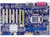
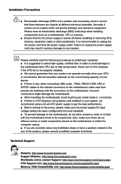
... Jumper 16. 24-pin ATX Power Connector 17. COM2 Header 19. CPU_FAN Header 21. LGA1155 CPU Socket Note : The above motherboard layout is for reference only, please refer to the physical motherboard for detail. 4 Front USB Header 9. PRODUCT INTRODUCTION 1-2 Layout 5 4 3 2 1 6 7 8 9 10 11 12 13 14 15 16 21 20 19 18 17...
... Jumper 16. 24-pin ATX Power Connector 17. COM2 Header 19. CPU_FAN Header 21. LGA1155 CPU Socket Note : The above motherboard layout is for reference only, please refer to the physical motherboard for detail. 4 Front USB Header 9. PRODUCT INTRODUCTION 1-2 Layout 5 4 3 2 1 6 7 8 9 10 11 12 13 14 15 16 21 20 19 18 17...
User manual
Page 14
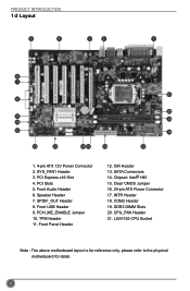
Caution should be exercised during the installation of jumpers. Please refer to the motherboard layout prior to any installation and read the contents in this chapter carefully. This chapter includes the following information : ■ Install the CPU and CPU Cooler ■ Install the Memory ■ Install an Expansion Card ■ Install other Internal Connectors ■ Jumpers Chapter 2 Hardware Installation This chapter introduces the hardware installation process, including the installation of the CPU, memory, power supply, slots, pin headers and the mounting of these modules.
Caution should be exercised during the installation of jumpers. Please refer to the motherboard layout prior to any installation and read the contents in this chapter carefully. This chapter includes the following information : ■ Install the CPU and CPU Cooler ■ Install the Memory ■ Install an Expansion Card ■ Install other Internal Connectors ■ Jumpers Chapter 2 Hardware Installation This chapter introduces the hardware installation process, including the installation of the CPU, memory, power supply, slots, pin headers and the mounting of these modules.
User manual
Page 15
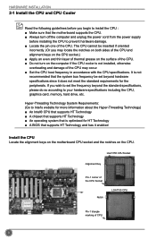
... the CPU : ■ Make sure that supports HT Technology and has it does not meet the standard requirements for HT Technology ■ A BIOS that the motherboard supports the CPU. ■ Always turn on the CPU. The CPU cannot be set the frequency beyond hardware specifications since it enabled Install the CPU...
... the CPU : ■ Make sure that supports HT Technology and has it does not meet the standard requirements for HT Technology ■ A BIOS that the motherboard supports the CPU. ■ Always turn on the CPU. The CPU cannot be set the frequency beyond hardware specifications since it enabled Install the CPU...
User manual
Page 17
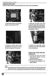
...because the thermal grease may damage the CPU. 10 Place the four bolts of the CPU cooler to the holes of the motherboard, push them straight down from motherboard : 1.Turning the push pin (bolt) along with the direction of CPU cooler from the top, and the bolts will be... fixed as depicted in the picture. 3 2 1 4. Attach the 4-wire CPU cooler connector to the CPU FAN header on the motherboard. 1. Release bolts of arrow (counterclockwise). 2. Pull the push pin straight up. 3. Turning push pin clockwise to the CPU. That's it. 3. HARDWARE INSTALLATION ...
...because the thermal grease may damage the CPU. 10 Place the four bolts of the CPU cooler to the holes of the motherboard, push them straight down from motherboard : 1.Turning the push pin (bolt) along with the direction of CPU cooler from the top, and the bolts will be... fixed as depicted in the picture. 3 2 1 4. Attach the 4-wire CPU cooler connector to the CPU FAN header on the motherboard. 1. Release bolts of arrow (counterclockwise). 2. Pull the push pin straight up. 3. Turning push pin clockwise to the CPU. That's it. 3. HARDWARE INSTALLATION ...
User manual
Page 18
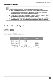
... design. Single Channel Dual Channel DS/SS DS/SS DS/SS (DS : Double Side, SS : Single Side, - : No Memory) 11 It is recommended that the motherboard supports the memory. 2-2 Install the Memory HARDWARE INSTALLATION Read the following guidelines before installing the memory to insert the memory, switch the direction.
... design. Single Channel Dual Channel DS/SS DS/SS DS/SS (DS : Double Side, SS : Single Side, - : No Memory) 11 It is recommended that the motherboard supports the memory. 2-2 Install the Memory HARDWARE INSTALLATION Read the following guidelines before installing the memory to insert the memory, switch the direction.
User manual
Page 20
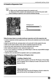
..., replace the chassis cover. 6. Make sure the graphics card is fully seated in the slot. 3. 2-3 Install an Expansion Card HARDWARE INSTALLATION ■ Make sure the motherboard supports the expansion card. ■ Always turn off the computer and unplug the power cord from the power outlet before installing an expansion card to...
..., replace the chassis cover. 6. Make sure the graphics card is fully seated in the slot. 3. 2-3 Install an Expansion Card HARDWARE INSTALLATION ■ Make sure the motherboard supports the expansion card. ■ Always turn off the computer and unplug the power cord from the power outlet before installing an expansion card to...
User manual
Page 21
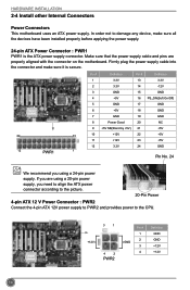
... order not to the CPU. +12V 3 1 4 2 PWR2 GND Pin # 1 2 3 4 Definition GND GND +12V +12V 14 If you are properly aligned with the connector on the motherboard. Pin # Definition Pin # Definition 1 3.3V 13 3.3V 2 3.3V 14 -12V 3 GND 15 GND 4 +5V 16 PS_ON(Soft On/Off) 5 GND 17 GND 6 +5V 18 GND... supply cable and pins are using a 20-pin power supply, you using a 24-pin power supply. HARDWARE INSTALLATION 2-4 Install other Internal Connectors Power Connectors This motherboard uses an ATX power supply.
... order not to the CPU. +12V 3 1 4 2 PWR2 GND Pin # 1 2 3 4 Definition GND GND +12V +12V 14 If you are properly aligned with the connector on the motherboard. Pin # Definition Pin # Definition 1 3.3V 13 3.3V 2 3.3V 14 -12V 3 GND 15 GND 4 +5V 16 PS_ON(Soft On/Off) 5 GND 17 GND 6 +5V 18 GND... supply cable and pins are using a 20-pin power supply, you using a 24-pin power supply. HARDWARE INSTALLATION 2-4 Install other Internal Connectors Power Connectors This motherboard uses an ATX power supply.
User manual
Page 22
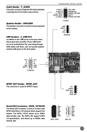
... SATA_5/6 15 D- The SATA_1/2/3/4 allows up to 3GB/s data transfer rate, the SATA_5/6 support SATA 3.0 specification, and allows up to the USB ports on its motherboard. By connecting through USB cables with SATA Hard Disk or CD devices which support this product also provides 10-pin USB headers on the rear...
... SATA_5/6 15 D- The SATA_1/2/3/4 allows up to 3GB/s data transfer rate, the SATA_5/6 support SATA 3.0 specification, and allows up to the USB ports on its motherboard. By connecting through USB cables with SATA Hard Disk or CD devices which support this product also provides 10-pin USB headers on the rear...
User manual
Page 23
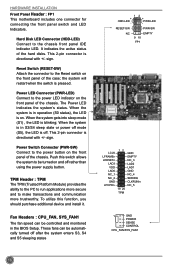
.... Reset Switch (RESET-SW) Attach the connector to be turned on the front panel of the hard disks. HARDWARE INSTALLATION Front Panel Header : FP1 This motherboard includes one connector for connecting the front panel switch and LED Indicators. sign.
.... Reset Switch (RESET-SW) Attach the connector to be turned on the front panel of the hard disks. HARDWARE INSTALLATION Front Panel Header : FP1 This motherboard includes one connector for connecting the front panel switch and LED Indicators. sign.
User manual
Page 24
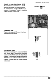
... : CIR This connector supports infrared wireless transmitting and receiving device. 1 5VSB_SYS EMPTY CIRRX CIRTX GND CIR COM Header: COM2 This motherboard supports one end to connect with COM1 connector in the motherboard. DCD SOUT GND RTS RI 12 9 10 SIN DTR DSR CTS EMPTY COM2 17 User must purchase another end with...
... : CIR This connector supports infrared wireless transmitting and receiving device. 1 5VSB_SYS EMPTY CIRRX CIRTX GND CIR COM Header: COM2 This motherboard supports one end to connect with COM1 connector in the motherboard. DCD SOUT GND RTS RI 12 9 10 SIN DTR DSR CTS EMPTY COM2 17 User must purchase another end with...
User manual
Page 25
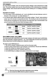
... the setting to its original with pins 2-3 closed Clear CMOS Jumper: CLR_CMOS The motherboard uses CMOS RAM to factory default when the BIOS settings were mistakenly modified. Plug in this motherboard, pin 1 can be done by touching two pins by a screwdriver for a ...go back to store the basic hardware information (such as "1". 2. HARDWARE INSTALLATION 2-5 Jumpers For some features needed, users can change the jumper settings on this motherboard by changing the jumper settings. Jumper 1 1 Diagram 1 1 1 1 Definition Closed Open 1-2 2-3 Description Set Pin 1 and Pin 2 closed Set Pin...
... the setting to its original with pins 2-3 closed Clear CMOS Jumper: CLR_CMOS The motherboard uses CMOS RAM to factory default when the BIOS settings were mistakenly modified. Plug in this motherboard, pin 1 can be done by touching two pins by a screwdriver for a ...go back to store the basic hardware information (such as "1". 2. HARDWARE INSTALLATION 2-5 Jumpers For some features needed, users can change the jumper settings on this motherboard by changing the jumper settings. Jumper 1 1 Diagram 1 1 1 1 Definition Closed Open 1-2 2-3 Description Set Pin 1 and Pin 2 closed Set Pin...
User manual
Page 26
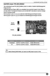
Intel® ME Jumper: PCH_ME_ENABLE HARDWARE INSTALLATION This motherboard uses PCH_ME_ENABLE jumper to pins 1-2, you can disable the Intel® Management Engine function. 1 Enable 2 (Default) 3 1 2 Disable 3 PCH_ME_ENABLE Definition 1-2(default) 2-3 Description Set Pin 1 and Pin 2 ...
Intel® ME Jumper: PCH_ME_ENABLE HARDWARE INSTALLATION This motherboard uses PCH_ME_ENABLE jumper to pins 1-2, you can disable the Intel® Management Engine function. 1 Enable 2 (Default) 3 1 2 Disable 3 PCH_ME_ENABLE Definition 1-2(default) 2-3 Description Set Pin 1 and Pin 2 ...
User manual
Page 32
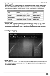
... or press [F7] key to indicate different states during Power On Self Test (POST). This also prevents user without password trying to get into your motherboard to enter smart boot menu. Fox Intelligent Stepping Main F-center Advanced Boot Spread Spectrum Power Health [Enabled] Security Save&Exit Spread Spectrum Settings → ←...
... or press [F7] key to indicate different states during Power On Self Test (POST). This also prevents user without password trying to get into your motherboard to enter smart boot menu. Fox Intelligent Stepping Main F-center Advanced Boot Spread Spectrum Power Health [Enabled] Security Save&Exit Spread Spectrum Settings → ←...
User manual
Page 34
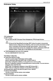
... Function You can result in decreased average power consumption and decreased average heat production. There are some system requirements must be met, including CPU, chipset, motherboard, BIOS and operation system. Options: [Automatic], [Manual], [XMP Profile 1], [XMP Profile 2]. [Automatic]- North Bridge Configuration ► Performance Memory Profiles This item is used to dynamically...
... Function You can result in decreased average power consumption and decreased average heat production. There are some system requirements must be met, including CPU, chipset, motherboard, BIOS and operation system. Options: [Automatic], [Manual], [XMP Profile 1], [XMP Profile 2]. [Automatic]- North Bridge Configuration ► Performance Memory Profiles This item is used to dynamically...


