User manual
Page 5
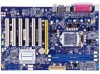
... a PCI Express x16 graphics card installed in your system. Technical Support Website: http://www.foxconnchannel.com Support Website: http://www.foxconnsupport.com Worldwide online contact Support: http://www.foxconnsupport.com/inquiry.aspx CPU Support List: http://www.foxconnsupport.com/cpusupportlist.aspx Memory, VGA Compatibility List: http://www.foxconnsupport.com/complist.aspx Never turn on the motherboard. Normally it comes out as a motherboard, CPU or memory. ■ Ensure that the DC power supply...
... a PCI Express x16 graphics card installed in your system. Technical Support Website: http://www.foxconnchannel.com Support Website: http://www.foxconnsupport.com Worldwide online contact Support: http://www.foxconnsupport.com/inquiry.aspx CPU Support List: http://www.foxconnsupport.com/cpusupportlist.aspx Memory, VGA Compatibility List: http://www.foxconnsupport.com/complist.aspx Never turn on the motherboard. Normally it comes out as a motherboard, CPU or memory. ■ Ensure that the DC power supply...
User manual
Page 6
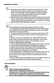
... Specifications 2 1-2 Layout...4 1-3 Back Panel Connectors 5 Chapter 2 Hardware Installation 2-1 Install the CPU and CPU Cooler 8 Install the CPU 8 Install the CPU Cooler 10 2-2 Install the Memory 11 Dual Channel Memory Configuration 11 Installing a Memory 12 2-3 Install an Expansion Card 13 2-4 Install other Internal Connectors 14 2-5 Jumpers 18 Chapter 3 BIOS Setup Enter BIOS Setup 21 Main...22 F-center...24 Smart BIOS 24 Fox Intelligent Stepping 25 CPU Configuration 26 Performance Tuning 27 Advanced...29 North Bridge 29 ME Subsystem 30 Onboard Device Configuration 31 SATA...
... Specifications 2 1-2 Layout...4 1-3 Back Panel Connectors 5 Chapter 2 Hardware Installation 2-1 Install the CPU and CPU Cooler 8 Install the CPU 8 Install the CPU Cooler 10 2-2 Install the Memory 11 Dual Channel Memory Configuration 11 Installing a Memory 12 2-3 Install an Expansion Card 13 2-4 Install other Internal Connectors 14 2-5 Jumpers 18 Chapter 3 BIOS Setup Enter BIOS Setup 21 Main...22 F-center...24 Smart BIOS 24 Fox Intelligent Stepping 25 CPU Configuration 26 Performance Tuning 27 Advanced...29 North Bridge 29 ME Subsystem 30 Onboard Device Configuration 31 SATA...
User manual
Page 14
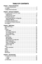
Chapter 2 Hardware Installation This chapter introduces the hardware installation process, including the installation of the CPU, memory, power supply, slots, pin headers and the mounting of these modules. This chapter includes the following information : ■ Install the CPU and CPU Cooler ■ Install the Memory ■ Install an Expansion Card ■ Install other Internal Connectors ■ Jumpers Caution should be exercised during the installation of jumpers. Please refer to the motherboard layout prior to any installation and read the contents in this chapter carefully.
Chapter 2 Hardware Installation This chapter introduces the hardware installation process, including the installation of the CPU, memory, power supply, slots, pin headers and the mounting of these modules. This chapter includes the following information : ■ Install the CPU and CPU Cooler ■ Install the Memory ■ Install an Expansion Card ■ Install other Internal Connectors ■ Jumpers Caution should be exercised during the installation of jumpers. Please refer to the motherboard layout prior to any installation and read the contents in this chapter carefully.
User manual
Page 20
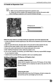
... graphics card is fully seated in the expansion slot. 1. Locate an expansion slot that supports your expansion card in the slot. 3. Installing and Removing a PCI Express x16 Graphics Card : • Installing a Graphics Card: Gently insert the graphics card into the slot. 4. 2-3 Install an Expansion Card HARDWARE INSTALLATION ■ Make sure the motherboard supports the expansion card. ■ Always turn off the computer and unplug the power cord from the power outlet before installing an expansion card to the chassis back panel with the slot...
... graphics card is fully seated in the expansion slot. 1. Locate an expansion slot that supports your expansion card in the slot. 3. Installing and Removing a PCI Express x16 Graphics Card : • Installing a Graphics Card: Gently insert the graphics card into the slot. 4. 2-3 Install an Expansion Card HARDWARE INSTALLATION ■ Make sure the motherboard supports the expansion card. ■ Always turn off the computer and unplug the power cord from the power outlet before installing an expansion card to the chassis back panel with the slot...
User manual
Page 23
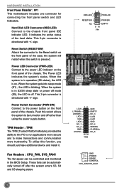
... power off mode (S5), the LED is off rather than using the power supply button. Power Switch Connector (PWR-SW) Connect to the Reset switch on the front panel of the hard disks. The Power LED indicates the system's status. It indicates the active status of the chassis. This 2-pin connector is directional with +/- Power LED Connector (PWR-LED) Connect to be turned on . This 2-pin connector is directional with +/- HARDWARE INSTALLATION Front Panel Header : FP1 This motherboard includes one connector for connecting the front panel switch...
... power off mode (S5), the LED is off rather than using the power supply button. Power Switch Connector (PWR-SW) Connect to the Reset switch on the front panel of the hard disks. The Power LED indicates the system's status. It indicates the active status of the chassis. This 2-pin connector is directional with +/- Power LED Connector (PWR-LED) Connect to be turned on . This 2-pin connector is directional with +/- HARDWARE INSTALLATION Front Panel Header : FP1 This motherboard includes one connector for connecting the front panel switch...
User manual
Page 25
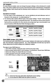
... power cable before adjusting the jumper settings. ■ Do not clear the CMOS while the system is the fast way to go back to factory default when the BIOS settings were mistakenly modified. Users should read the following table explains different types of Jumpers 1. HARDWARE INSTALLATION 2-5 Jumpers For some features needed, users can change the jumper settings on the two pins to temporarily short them. For any jumper setting. However, in this motherboard...
... power cable before adjusting the jumper settings. ■ Do not clear the CMOS while the system is the fast way to go back to factory default when the BIOS settings were mistakenly modified. Users should read the following table explains different types of Jumpers 1. HARDWARE INSTALLATION 2-5 Jumpers For some features needed, users can change the jumper settings on the two pins to temporarily short them. For any jumper setting. However, in this motherboard...
User manual
Page 26
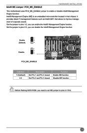
Set the jumper to pins 2-3, you need to set ME jumper to pins 1-2, you can disable the Intel® Management Engine function. 1 Enable 2 (Default) 3 1 2 Disable 3 PCH_ME_ENABLE Definition 1-2(default) 2-3 Description Set Pin 1 and Pin 2 closed Set Pin 2 and Pin 3 closed Function Enable ME function Disable ME function CAUTION Before flashing BIOS ROM, you can enable the Intel® Management Engine function. Intel® ME Jumper: PCH_ME_ENABLE HARDWARE INSTALLATION This motherboard uses PCH_ME_ENABLE jumper to improve management of corporate assets. It...
Set the jumper to pins 2-3, you need to set ME jumper to pins 1-2, you can disable the Intel® Management Engine function. 1 Enable 2 (Default) 3 1 2 Disable 3 PCH_ME_ENABLE Definition 1-2(default) 2-3 Description Set Pin 1 and Pin 2 closed Set Pin 2 and Pin 3 closed Function Enable ME function Disable ME function CAUTION Before flashing BIOS ROM, you can enable the Intel® Management Engine function. Intel® ME Jumper: PCH_ME_ENABLE HARDWARE INSTALLATION This motherboard uses PCH_ME_ENABLE jumper to improve management of corporate assets. It...
User manual
Page 28
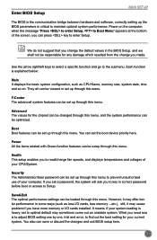
... adjust BIOS setting one by one, trial and error, to find out the best setting for any damage which resulted from the change you change fan speeds, and displays temperatures and voltages of the screen, you have more memory or I/O cards installed. Use the arrow right/left keys to select a specific function and go to enter Setup. You can be setup through this menu. Security The Administrator/User password can set up through this menu. Save...
... adjust BIOS setting one by one, trial and error, to find out the best setting for any damage which resulted from the change you change fan speeds, and displays temperatures and voltages of the screen, you have more memory or I/O cards installed. Use the arrow right/left keys to select a specific function and go to enter Setup. You can be setup through this menu. Security The Administrator/User password can set up through this menu. Save...
User manual
Page 31
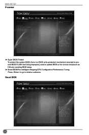
... Control Center Super BIOS Protect ▶ Smart BIOS ▶ Fox Intelligent Stepping ▶ CPU Configuration ▶ Performance Tuning Power Health [Enabled] Security Save&Exit Super BIOS Protection Settings → ←: Select Screen ↑ ↓/Click: Select Item Enter/Dbl Click: Select +/-: Change Opt. F1: General Help F2: Previous Values F3: Optimized Defaults F4: Save & Exit ESC/Right Click: Exit Version 2.14.1219. Smart BIOS Main F-center Advanced Boot Smart BIOS Power Health Smart Power LED Smart Boot Menu [Disabled] [Enabled...
... Control Center Super BIOS Protect ▶ Smart BIOS ▶ Fox Intelligent Stepping ▶ CPU Configuration ▶ Performance Tuning Power Health [Enabled] Security Save&Exit Super BIOS Protection Settings → ←: Select Screen ↑ ↓/Click: Select Item Enter/Dbl Click: Select +/-: Change Opt. F1: General Help F2: Previous Values F3: Optimized Defaults F4: Save & Exit ESC/Right Click: Exit Version 2.14.1219. Smart BIOS Main F-center Advanced Boot Smart BIOS Power Health Smart Power LED Smart Boot Menu [Disabled] [Enabled...
User manual
Page 32
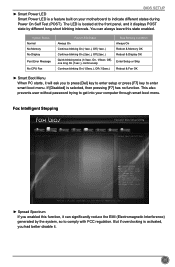
... EMI (Electromagnetic Interference) generated by different long-short blinking intervals. System Status Normal No Memory No Display Post Error Message No CPU Fan Power LED Status Always On Continue blinking On (1sec.), Off (1sec.) Continue blinking On (2sec.), Off (2sec.) Quick blinking twice (1/3sec. This also prevents user without password trying to get into your motherboard to enter smart boot menu. If [Disabled] is selected, then pressing [F7...
... EMI (Electromagnetic Interference) generated by different long-short blinking intervals. System Status Normal No Memory No Display Post Error Message No CPU Fan Power LED Status Always On Continue blinking On (1sec.), Off (1sec.) Continue blinking On (2sec.), Off (2sec.) Quick blinking twice (1/3sec. This also prevents user without password trying to get into your motherboard to enter smart boot menu. If [Disabled] is selected, then pressing [F7...
User manual
Page 33
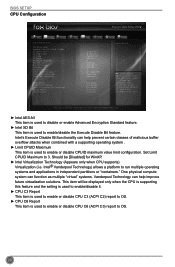
... setting is used to enable/disable it. ► CPU C3 Report This item is used to enable or disable CPU C3 (ACPI C2) report to OS. ► CPU C6 Report This item is used to enable or disable CPU C6 (ACPI C3) report to OS. 26 BIOS SETUP CPU Configuration Main F-center Advanced Boot CPU Configuration CPU Brand Name: Genuine Intel(R) CPU @ 2.20GHz L1 Data Cache L1 Code Cache L2 Cache L3 Cache Processor Stepping Max CPU Speed Min CPU Speed CPU Speed Processor Cores Intel HT Technology...
... setting is used to enable/disable it. ► CPU C3 Report This item is used to enable or disable CPU C3 (ACPI C2) report to OS. ► CPU C6 Report This item is used to enable or disable CPU C6 (ACPI C3) report to OS. 26 BIOS SETUP CPU Configuration Main F-center Advanced Boot CPU Configuration CPU Brand Name: Genuine Intel(R) CPU @ 2.20GHz L1 Data Cache L1 Code Cache L2 Cache L3 Cache Processor Stepping Max CPU Speed Min CPU Speed CPU Speed Processor Cores Intel HT Technology...
User manual
Page 34
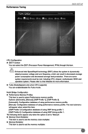
... CPU, chipset, motherboard, BIOS and operation system. North Bridge Configuration ► Performance Memory Profiles This item is used to set the memory multiplier. 27 Configuration database of using XMP timing profile 1. F1: General Help F2: Previous Values F3: Optimized Defaults F4: Save & Exit ESC/Right Click: Exit Version 2.14.1219. The next submenu will appear when select this item. Performance Tuning BIOS SETUP Main F-center Advanced Boot Power...
... CPU, chipset, motherboard, BIOS and operation system. North Bridge Configuration ► Performance Memory Profiles This item is used to set the memory multiplier. 27 Configuration database of using XMP timing profile 1. F1: General Help F2: Previous Values F3: Optimized Defaults F4: Save & Exit ESC/Right Click: Exit Version 2.14.1219. The next submenu will appear when select this item. Performance Tuning BIOS SETUP Main F-center Advanced Boot Power...
User manual
Page 37
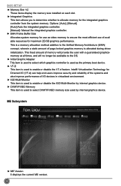
.... Manual the integrated graphics controller. ► UMA Frame Buffer Size Allocates system memory for maximum 2D/3D graphics performance. ME Subsystem Main F-center Advanced Boot Intel ME Subsystem Configuration ME Version Power N/A Health Security Save&Exit → ←: Select Screen ↑ ↓/Click: Select Item Enter/Dbl Click: Select +/-: Change Opt. Copyright (C) 2012 American Megatrends, Inc. ► ME Version It displays the current ME version. 30 BIOS SETUP ► Memory Slot...
.... Manual the integrated graphics controller. ► UMA Frame Buffer Size Allocates system memory for maximum 2D/3D graphics performance. ME Subsystem Main F-center Advanced Boot Intel ME Subsystem Configuration ME Version Power N/A Health Security Save&Exit → ←: Select Screen ↑ ↓/Click: Select Item Enter/Dbl Click: Select +/-: Change Opt. Copyright (C) 2012 American Megatrends, Inc. ► ME Version It displays the current ME version. 30 BIOS SETUP ► Memory Slot...
User manual
Page 38
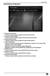
Onboard Device Configuration BIOS SETUP Main F-center Advanced Boot Power Health Security Save&Exit Onboard Device Configuration Onboard LAN Controller Onboard LAN PXE OpROM Onboard USB Controller Legacy USB Support USB3.0 Support SATA3.0 Controller Azalia HD Audio Controller [Enabled] [Enabled] [Enabled] [Enabled] [Enabled] [Enabled] [Enabled] Onboard LAN Controller → ←: Select Screen ↑ ↓/Click: Select Item Enter/Dbl Click: Select +/-: Change Opt. Copyright (C) 2012 American Megatrends, Inc. ► Onboard LAN Controller This item is used to enable ...
Onboard Device Configuration BIOS SETUP Main F-center Advanced Boot Power Health Security Save&Exit Onboard Device Configuration Onboard LAN Controller Onboard LAN PXE OpROM Onboard USB Controller Legacy USB Support USB3.0 Support SATA3.0 Controller Azalia HD Audio Controller [Enabled] [Enabled] [Enabled] [Enabled] [Enabled] [Enabled] [Enabled] Onboard LAN Controller → ←: Select Screen ↑ ↓/Click: Select Item Enter/Dbl Click: Select +/-: Change Opt. Copyright (C) 2012 American Megatrends, Inc. ► Onboard LAN Controller This item is used to enable ...
User manual
Page 39
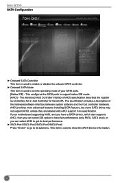
... (AHCI) specification describes the register level interface for a Host Controller for Serial ATA. This item is used to set the operating mode of the hardware/software interface between system software and the host controller hardware. If your SATA ports. [Native IDE] - BIOS SETUP SATA Configuration Main F-center Advanced Boot Power Health Security Save&Exit SATA Configuration Onboard SATA Controller Onboard SATA Mode ▶ SATA Port1: Not Present ▶ SATA Port2: Not Present ▶ SATA Port3: Not Present ▶ SATA Port4: Not Present [Enabled...
... (AHCI) specification describes the register level interface for a Host Controller for Serial ATA. This item is used to set the operating mode of the hardware/software interface between system software and the host controller hardware. If your SATA ports. [Native IDE] - BIOS SETUP SATA Configuration Main F-center Advanced Boot Power Health Security Save&Exit SATA Configuration Onboard SATA Controller Onboard SATA Mode ▶ SATA Port1: Not Present ▶ SATA Port2: Not Present ▶ SATA Port3: Not Present ▶ SATA Port4: Not Present [Enabled...
User manual
Page 40
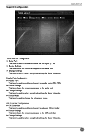
... to enable or disable the onboard CIR controller. ► Device Settings This item shows the resource assigned to the CIR controller. ► Change Settings This item is used to select an optimal settings for Super IO device. Super IO Configuration BIOS SETUP Main F-center Advanced Boot Power Health Security Save&Exit Super IO Configuration Super IO Chip IT8728 Set Parameters of Serial Port 1 (COMB) ▶ Serial Port 0 Configuration ▶ Serial Port 1 Configuration ▶ Parallel Port Configuration ▶ CIR Controller Configuration → ←: Select Screen...
... to enable or disable the onboard CIR controller. ► Device Settings This item shows the resource assigned to the CIR controller. ► Change Settings This item is used to select an optimal settings for Super IO device. Super IO Configuration BIOS SETUP Main F-center Advanced Boot Power Health Security Save&Exit Super IO Configuration Super IO Chip IT8728 Set Parameters of Serial Port 1 (COMB) ▶ Serial Port 0 Configuration ▶ Serial Port 1 Configuration ▶ Parallel Port Configuration ▶ CIR Controller Configuration → ←: Select Screen...
User manual
Page 41
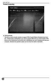
.... ► TPM SUPPORT This item is used to decide whether to [Enabled], then save changing and reset your computer, otherwise the operation system can not show TPM.Reset of platform is [Disabled]. F1: General Help F2: Previous Values F3: Optimized Defaults F4: Save & Exit ESC/Right Click: Exit Version 2.14.1219. BIOS SETUP Trusted Computing Main F-center Advanced Boot TPM Configuration TPM SUPPORT Current TPM...
.... ► TPM SUPPORT This item is used to decide whether to [Enabled], then save changing and reset your computer, otherwise the operation system can not show TPM.Reset of platform is [Disabled]. F1: General Help F2: Previous Values F3: Optimized Defaults F4: Save & Exit ESC/Right Click: Exit Version 2.14.1219. BIOS SETUP Trusted Computing Main F-center Advanced Boot TPM Configuration TPM SUPPORT Current TPM...
User manual
Page 47
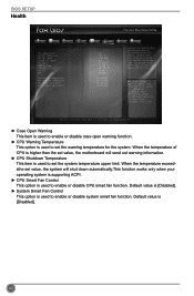
...send out warning information. ► CPU Shutdown Temperature This item is used to set the system temperature upper limit. Default value is [Disabled]. ► System Smart Fan Control This option is used to enable or disable system smart fan function. BIOS SETUP Health Main F-center Advanced Boot Case Open Warning CPU Temperature System Temperature CPU Fan Speed System Fan Speed CPU Vcore DRAM Voltage +12V SYS +5V SYS VBAT CPU Warning Temperature CPU Shutdowm Temperature CPU Smart Fan Control System Smart Fan Control Power Health [Disabled] : +39 ˚C : +35 ˚C : 3026...
...send out warning information. ► CPU Shutdown Temperature This item is used to set the system temperature upper limit. Default value is [Disabled]. ► System Smart Fan Control This option is used to enable or disable system smart fan function. BIOS SETUP Health Main F-center Advanced Boot Case Open Warning CPU Temperature System Temperature CPU Fan Speed System Fan Speed CPU Vcore DRAM Voltage +12V SYS +5V SYS VBAT CPU Warning Temperature CPU Shutdowm Temperature CPU Smart Fan Control System Smart Fan Control Power Health [Disabled] : +39 ˚C : +35 ˚C : 3026...
User manual
Page 51
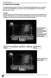
... INSTRUCTION 4-1 Install driver and utility This motherboard comes with one DVD, after installing the Operating System, you can simply put it into your DVD-ROM drive, and the main menu will be displayed on each individual driver to install all the drivers for your PC screen to guide you how to install it manually. Manual Installation Step by Step Automatic Installation by One Click Drop to System Tray Exit the program Visit Foxconn's Show Utilities...
... INSTRUCTION 4-1 Install driver and utility This motherboard comes with one DVD, after installing the Operating System, you can simply put it into your DVD-ROM drive, and the main menu will be displayed on each individual driver to install all the drivers for your PC screen to guide you how to install it manually. Manual Installation Step by Step Automatic Installation by One Click Drop to System Tray Exit the program Visit Foxconn's Show Utilities...
User manual
Page 52
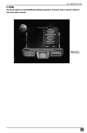
Click here 45 CD INSTRUCTION 2. Utility Use these options to install additional software programs. And click "User's manual" button to view the product manual.
Click here 45 CD INSTRUCTION 2. Utility Use these options to install additional software programs. And click "User's manual" button to view the product manual.


