English Manual.
Page 11
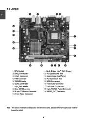
.... North Bridge: Intel® G41 Chipset 12. PCI Express x16 Slot 13. PCI Express x1 Slot 15. CPU_FAN Header 8. CPU Socket 2. DDR2 DIMM Slot 7. Front Panel Connector 9 87 6 5 11. Clear CMOS Jumper 9. 24-pin ATX Power Connector 10. SYS_FAN Header 3. COM1 Connector 4. S/PDIF_OUT Connector Note : The above motherboard layout is for reference only...
.... North Bridge: Intel® G41 Chipset 12. PCI Express x16 Slot 13. PCI Express x1 Slot 15. CPU_FAN Header 8. CPU Socket 2. DDR2 DIMM Slot 7. Front Panel Connector 9 87 6 5 11. Clear CMOS Jumper 9. 24-pin ATX Power Connector 10. SYS_FAN Header 3. COM1 Connector 4. S/PDIF_OUT Connector Note : The above motherboard layout is for reference only...
English Manual.
Page 18
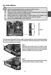
...module, and push it down firmly and seat it vertically into the memory socket. Read the following guidelines before installing the memory to install DDR2 DIMM on both ends of memory module, it can be installed in only one direction. Place the memory module onto the socket, then put...A memory module can only fit in the middle, so it has asymmetric pin counts on this motherboard. 2 112-Pin 128-Pin Notch If you begin to install the memory : ■ Make sure that the motherboard supports the memory. ■ Always turn off the computer and unplug the power cord from the...
...module, and push it down firmly and seat it vertically into the memory socket. Read the following guidelines before installing the memory to install DDR2 DIMM on both ends of memory module, it can be installed in only one direction. Place the memory module onto the socket, then put...A memory module can only fit in the middle, so it has asymmetric pin counts on this motherboard. 2 112-Pin 128-Pin Notch If you begin to install the memory : ■ Make sure that the motherboard supports the memory. ■ Always turn off the computer and unplug the power cord from the...


