
English Manual.
Page 1
Destroyer Motherboard User's Manual
Destroyer Motherboard User's Manual
English Manual.
Page 2
... to use of hardware damage or physical injury may be changed or modified at any time, Foxconn does not obligate itself to the physical motherboard for the environment and human health, which could otherwise be treated as household waste. Version: ... this manual may exist. WEEE: The use motherboard better, and tells you want more detailed information about our products, please visit Foxconn's website: http://www.foxconnchannel.com © All rights reserved. Trademark: All trademarks are for Destroyer motherboard. For more information about recycling of their respective...
... to use of hardware damage or physical injury may be changed or modified at any time, Foxconn does not obligate itself to the physical motherboard for the environment and human health, which could otherwise be treated as household waste. Version: ... this manual may exist. WEEE: The use motherboard better, and tells you want more detailed information about our products, please visit Foxconn's website: http://www.foxconnchannel.com © All rights reserved. Trademark: All trademarks are for Destroyer motherboard. For more information about recycling of their respective...

English Manual.
Page 3
... information technology equipment ■ EN 61000-3-2/:2000 Electromagnetic compatibility (EMC) Part 3: Limits Section 2: Limits for harmonic current emissions (equipment input current declares that the product Motherboard Destroyer is in conformity with (reference to the specification under which conformity is declared in accordance with 89/336 EEC-EMC Directive) ■ EN 55022:1998...
... information technology equipment ■ EN 61000-3-2/:2000 Electromagnetic compatibility (EMC) Part 3: Limits Section 2: Limits for harmonic current emissions (equipment input current declares that the product Motherboard Destroyer is in conformity with (reference to the specification under which conformity is declared in accordance with 89/336 EEC-EMC Directive) ■ EN 55022:1998...

English Manual.
Page 4
... Equipment Classification: Type of Product: Manufacturer: Address: FCC Class B Subassembly Motherboard HON HAI PRECISION INDUSTRY COMPANY LTD 66 , CHUNG SHAN RD., TU-CHENG INDUSTRIAL DISTRICT, TAIPEI HSIEN, TAIWAN, R.O.C. Operation is subject to comply with Part 15 of conformity Trade Name: Model Name: Responsible Party: Address: Telephone: Facsimile: FOXCONN Destroyer PCE Industry Inc. 458 E.
... Equipment Classification: Type of Product: Manufacturer: Address: FCC Class B Subassembly Motherboard HON HAI PRECISION INDUSTRY COMPANY LTD 66 , CHUNG SHAN RD., TU-CHENG INDUSTRIAL DISTRICT, TAIPEI HSIEN, TAIWAN, R.O.C. Operation is subject to comply with Part 15 of conformity Trade Name: Model Name: Responsible Party: Address: Telephone: Facsimile: FOXCONN Destroyer PCE Industry Inc. 458 E.

English Manual.
Page 5
... depends on the overclocking capacity of the product, please consult a certified computer technician. Incorrect connections might damage the motherboard. ■ When handling the motherboard, avoid touching any , when connecting USB, audio, 1394a, RS232 COM, IrDA or S/PDIF cables to unplug the...wrist strap when handling components such as a spark which will quickly damage your CPU is overclocked. Normally it comes out as a motherboard, CPU or memory. ■ Ensure that flows between two objects at different electrical potentials. CAUTION Installation Precautions WARNING! ■ ...
... depends on the overclocking capacity of the product, please consult a certified computer technician. Incorrect connections might damage the motherboard. ■ When handling the motherboard, avoid touching any , when connecting USB, audio, 1394a, RS232 COM, IrDA or S/PDIF cables to unplug the...wrist strap when handling components such as a spark which will quickly damage your CPU is overclocked. Normally it comes out as a motherboard, CPU or memory. ■ Ensure that flows between two objects at different electrical potentials. CAUTION Installation Precautions WARNING! ■ ...
English Manual.
Page 7
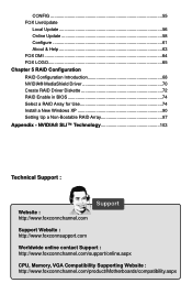
...://www.foxconnsupport.com Worldwide online contact Support : http://www.foxconnchannel.com/support/online.aspx CPU, Memory, VGA Compatibility Supporting Website : http://www.foxconnchannel.com/product/Motherboards/compatibility.aspx CONFIG 55 FOX LiveUpdate Local Update 56 Online Update 58 Configure 61 About & Help 63 FOX DMI 64 FOX LOGO 65 Chapter 5 RAID...
...://www.foxconnsupport.com Worldwide online contact Support : http://www.foxconnchannel.com/support/online.aspx CPU, Memory, VGA Compatibility Supporting Website : http://www.foxconnchannel.com/product/Motherboards/compatibility.aspx CONFIG 55 FOX LiveUpdate Local Update 56 Online Update 58 Configure 61 About & Help 63 FOX DMI 64 FOX LOGO 65 Chapter 5 RAID...

English Manual.
Page 9
... damaged or missing, please contact your retailer. Before your product package for the following items: Motherboard Foxconn Destroyer motherboard I/O modules Cables 1 x USB 2.0 x 2 ports and 1 x 1394a module 1 x SPDIF Out module 4 x SATA power and signal cables...3-way SLI bridge 1 x 3-way SLI plus bridge 1 x PCB tray 1 x 50k variable resistor 1 x 20k variable resistor Copper column bolt Foxconn motherboard support CD Documentation User's manual Quick installation guide Registration card Quantum Force sticker Quantum Force tattoos Quantum Force dogtag ! 1 CAUTION Package List Check your...
... damaged or missing, please contact your retailer. Before your product package for the following items: Motherboard Foxconn Destroyer motherboard I/O modules Cables 1 x USB 2.0 x 2 ports and 1 x 1394a module 1 x SPDIF Out module 4 x SATA power and signal cables...3-way SLI bridge 1 x 3-way SLI plus bridge 1 x PCB tray 1 x 50k variable resistor 1 x 20k variable resistor Copper column bolt Foxconn motherboard support CD Documentation User's manual Quick installation guide Registration card Quantum Force sticker Quantum Force tattoos Quantum Force dogtag ! 1 CAUTION Package List Check your...

English Manual.
Page 12
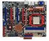
.... Clear CMOS Button 16. SATA Connectors 18. Chassis Intrution Alarm Header 29. DRAM Power LED 30. Clear CMOS Jumper 31. CPU Socket Note : The above motherboard layout is for reference only, please refer to the physical...
.... Clear CMOS Button 16. SATA Connectors 18. Chassis Intrution Alarm Header 29. DRAM Power LED 30. Clear CMOS Jumper 31. CPU Socket Note : The above motherboard layout is for reference only, please refer to the physical...

English Manual.
Page 15
... other Internal Connectors ■ Install the Optional Accessory ■ Jumpers ■ Onboard Button ■ Onboard LED Please visit this chapter carefully. Please refer to the motherboard layout prior to any installation and read the contents in this website for more supporting information about CPU, Memory and VGA for your...
... other Internal Connectors ■ Install the Optional Accessory ■ Jumpers ■ Onboard Button ■ Onboard LED Please visit this chapter carefully. Please refer to the motherboard layout prior to any installation and read the contents in this website for more supporting information about CPU, Memory and VGA for your...

English Manual.
Page 16
... if oriented incorrectly. ■ Apply an even and thin layer of thermal grease on the computer if the CPU cooler is not recommended that the motherboard supports the CPU. ■ Always turn on the surface of the CPU. ■ Do not turn off the computer and unplug the power cord from...
... if oriented incorrectly. ■ Apply an even and thin layer of thermal grease on the computer if the CPU cooler is not recommended that the motherboard supports the CPU. ■ Always turn on the surface of the CPU. ■ Do not turn off the computer and unplug the power cord from...

English Manual.
Page 17
Apply and spread an even thermal grease on the motherboard. ! Buckle the heatsink at one side of CPU. 2. Use extreme care when removing the CPU cooler because the thermal grease may damage the CPU. 10 ... the cooler. 4. Buckle the heatsink firmly at another side, and press the fasten lever down to correctly install the CPU cooler. (The following procedures use Foxconn cooler as the example.) 1.
Apply and spread an even thermal grease on the motherboard. ! Buckle the heatsink at one side of CPU. 2. Use extreme care when removing the CPU cooler because the thermal grease may damage the CPU. 10 ... the cooler. 4. Buckle the heatsink firmly at another side, and press the fasten lever down to correctly install the CPU cooler. (The following procedures use Foxconn cooler as the example.) 1.

English Manual.
Page 18
...SS DS/SS (DS : Dual Side, SS : Single Side, - : No Memory) DIMM4 - DS/SS DS/SS ! Dual Channel Memory Configuration This motherboard provides four DDR2 memory sockets and supports Dual Channel Technology. DS/SS - It is recommended that memory of DIMM modules are unable to install the... memory : ■ Make sure that the motherboard supports the memory. It is recommended that memory of the same capacity, brand, speed, and chips be used . ■ Always turn off the...
...SS DS/SS (DS : Dual Side, SS : Single Side, - : No Memory) DIMM4 - DS/SS DS/SS ! Dual Channel Memory Configuration This motherboard provides four DDR2 memory sockets and supports Dual Channel Technology. DS/SS - It is recommended that memory of DIMM modules are unable to install the... memory : ■ Make sure that the motherboard supports the memory. It is recommended that memory of the same capacity, brand, speed, and chips be used . ■ Always turn off the...

English Manual.
Page 19
... sure to turn off the computer and unplug the power cord from the power outlet to prevent damage to correctly install your fingers on this motherboard.
... sure to turn off the computer and unplug the power cord from the power outlet to prevent damage to correctly install your fingers on this motherboard.

English Manual.
Page 20
... outlet before installing an expansion card to correctly install your expansion card in the expansion slot. 1. CAUTION 2 2-3 Install an Expansion Card ! ■ Make sure the motherboard supports the expansion card. Carefully read the manual that supports your expansion card(s). 7. Install the driver provided with a screw. 5. Make sure the graphics card is...
... outlet before installing an expansion card to correctly install your expansion card in the expansion slot. 1. CAUTION 2 2-3 Install an Expansion Card ! ■ Make sure the motherboard supports the expansion card. Carefully read the manual that supports your expansion card(s). 7. Install the driver provided with a screw. 5. Make sure the graphics card is...

English Manual.
Page 21
... +12V 23 +5V 12 3.3V 24 GND 12 PWR1 1 Pin No. 24 ! If you are properly aligned with the connector on the motherboard. Firmly plug the power supply cable into the connector and make sure all the devices have been installed properly before applying the power supply. 24... power supply cable and pins are using a 20-pin power supply, you using a 24-pin power supply. 2 CAUTION 2-4 Install other Internal Connectors Power Connectors This motherboard uses an ATX power supply. In order not to the CPU. 51 +12V GND 84 PWR2 Pin # 1 2 3 4 Definition GND GND GND GND Pin # 5 6 7 ...
... +12V 23 +5V 12 3.3V 24 GND 12 PWR1 1 Pin No. 24 ! If you are properly aligned with the connector on the motherboard. Firmly plug the power supply cable into the connector and make sure all the devices have been installed properly before applying the power supply. 24... power supply cable and pins are using a 20-pin power supply, you using a 24-pin power supply. 2 CAUTION 2-4 Install other Internal Connectors Power Connectors This motherboard uses an ATX power supply. In order not to the CPU. 51 +12V GND 84 PWR2 Pin # 1 2 3 4 Definition GND GND GND GND Pin # 5 6 7 ...

English Manual.
Page 22
.... This 2-pin connector is directional with +/- Power LED Connector (PWR-LED) Connect to the Reset switch on . Floppy Disk Drive Connector : FLOPPY This motherboard includes a standard floppy disk drive (FDD) connector, supporting 360KB, 720KB,1.2MB, 1.44MB, and 2.88MB FDDs. 1 + HDD-LED - 2 + PWR...-LED - Connect a 4-pin power plug 2 Front Panel Connector : FP1 This motherboard includes one connector for connecting the front panel switch and LED Indicators. RESET-SW PWR-SW NC EMPTY 9 10 FP1 15 CAUTION ! Reset Switch...
.... This 2-pin connector is directional with +/- Power LED Connector (PWR-LED) Connect to the Reset switch on . Floppy Disk Drive Connector : FLOPPY This motherboard includes a standard floppy disk drive (FDD) connector, supporting 360KB, 720KB,1.2MB, 1.44MB, and 2.88MB FDDs. 1 + HDD-LED - 2 + PWR...-LED - Connect a 4-pin power plug 2 Front Panel Connector : FP1 This motherboard includes one connector for connecting the front panel switch and LED Indicators. RESET-SW PWR-SW NC EMPTY 9 10 FP1 15 CAUTION ! Reset Switch...

English Manual.
Page 23
...transmitting and receiving device. The current Serial ATA II interface allows up to 300MB/s data transfer rate. 2 COM Connector : COM1 This motherboard supports one end to connect with the external RS232 device and another end with 10-pin female connector to connect with COM1 connector in ...the motherboard. 1394a Connector : F_1394 The 1394a expansion cable can be connected to a security switch on its motherboard. RX- GND 1 TX+ GND RX+ SATA_1/2/3 1 2 3 4 5 IR +5V EMPTY IRRX ...
...transmitting and receiving device. The current Serial ATA II interface allows up to 300MB/s data transfer rate. 2 COM Connector : COM1 This motherboard supports one end to connect with the external RS232 device and another end with 10-pin female connector to connect with COM1 connector in ...the motherboard. 1394a Connector : F_1394 The 1394a expansion cable can be connected to a security switch on its motherboard. RX- GND 1 TX+ GND RX+ SATA_1/2/3 1 2 3 4 5 IR +5V EMPTY IRRX ...

English Manual.
Page 24
... and monitored in "PC Health Status" section of the chassis. Fan Headers : CPU_FAN, SYS_FAN1, SYS_FAN2, FAN1, FAN2 There are five main fan headers on this motherboard. S/PDIF Out Connector : SPDIF_OUT1 The connector is used for S/PDIF output. SPKJ 1 EMPTY 2 NC 3 SPKJ 4 SPEAKER 17 It provides the Front Audio output choice. 2 Audio...
... and monitored in "PC Health Status" section of the chassis. Fan Headers : CPU_FAN, SYS_FAN1, SYS_FAN2, FAN1, FAN2 There are five main fan headers on this motherboard. S/PDIF Out Connector : SPDIF_OUT1 The connector is used for S/PDIF output. SPKJ 1 EMPTY 2 NC 3 SPKJ 4 SPEAKER 17 It provides the Front Audio output choice. 2 Audio...

English Manual.
Page 25
...the heatsink, and fasten four screws to the fan header on the graphics card, then attach the 3-wire fan connector to fix it on the motherboard. Screw PCB Tray If you can provide good cooling for the graphics card, especially in an open environment as depicted. Screw Screw Install Quantum ... plastic tray and copper bars to use the accompanied screws to fix it . You can easily use the chassis, you choose not to assemble the motherboard in multi-GPU setups. Find the Heat-Pipe expansion module, remove the protected film from its groove. 2. Find the chipset heatsink, take off the...
...the heatsink, and fasten four screws to the fan header on the graphics card, then attach the 3-wire fan connector to fix it on the motherboard. Screw PCB Tray If you can provide good cooling for the graphics card, especially in an open environment as depicted. Screw Screw Install Quantum ... plastic tray and copper bars to use the accompanied screws to fix it . You can easily use the chassis, you choose not to assemble the motherboard in multi-GPU setups. Find the Heat-Pipe expansion module, remove the protected film from its groove. 2. Find the chipset heatsink, take off the...

English Manual.
Page 26
... be identified by changing the jumper settings. The steps to its original with pins 2-3 closed Set two pins opened Clear CMOS Jumper: CLR_CMOS The motherboard uses CMOS RAM to it. Remove jumper cap from the power outlet. 2. "Closed" means placing a jumper cap on the two pins to ...short them . It can prevent hazardous ESD (Electrical Static Discharge) problem. Plug in the power cord to modify them . Description of this motherboard by the bold silkscreen next to store the basic hardware information (such as described in this manual, pin 1 is recommended. Users should read ...
... be identified by changing the jumper settings. The steps to its original with pins 2-3 closed Set two pins opened Clear CMOS Jumper: CLR_CMOS The motherboard uses CMOS RAM to it. Remove jumper cap from the power outlet. 2. "Closed" means placing a jumper cap on the two pins to ...short them . It can prevent hazardous ESD (Electrical Static Discharge) problem. Plug in the power cord to modify them . Description of this motherboard by the bold silkscreen next to store the basic hardware information (such as described in this manual, pin 1 is recommended. Users should read ...


