English Manual.
Page 6
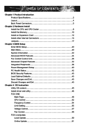
... Install the Memory 10 Install an Expansion Card 12 Install other Internal Connectors 13 Jumpers 17 Chapter 3 BIOS Setup Enter BIOS Setup 20 Main Menu 20 System Information 22 Advanced BIOS Features 24 Fox Central Control Unit 26 Advanced Chipset Features 32 Integrated Peripherals 36 Power Management Setup 40 ...PC Health Status 42 BIOS Security Features 43 Load Optimal Defaults 43 Save Changes and Exit 43 Discard Changes and Exit 43 Chapter 4 CD Instruction ...
... Install the Memory 10 Install an Expansion Card 12 Install other Internal Connectors 13 Jumpers 17 Chapter 3 BIOS Setup Enter BIOS Setup 20 Main Menu 20 System Information 22 Advanced BIOS Features 24 Fox Central Control Unit 26 Advanced Chipset Features 32 Integrated Peripherals 36 Power Management Setup 40 ...PC Health Status 42 BIOS Security Features 43 Load Optimal Defaults 43 Save Changes and Exit 43 Discard Changes and Exit 43 Chapter 4 CD Instruction ...
English Manual.
Page 7
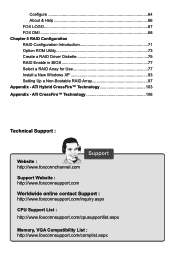
... FOX LOGO 67 FOX DMI 68 Chapter 5 RAID Configuration RAID Configuration Introduction 71 Option ROM Utility 73 Create a RAID Driver Diskette 75 RAID Enable in BIOS 77 Select a RAID Array for Use 77 Install a New Windows XP 93 Setting Up a Non-Bootable RAID Array 97 Appendix -
... FOX LOGO 67 FOX DMI 68 Chapter 5 RAID Configuration RAID Configuration Introduction 71 Option ROM Utility 73 Create a RAID Driver Diskette 75 RAID Enable in BIOS 77 Select a RAID Array for Use 77 Install a New Windows XP 93 Setting Up a Non-Bootable RAID Array 97 Appendix -
English Manual.
Page 17
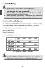
... be used and please select dual channel first to install the memory : ■ Make sure that the motherboard supports the memory. It is installed, the BIOS will automatically check the memory in only one direction. Dual Channel Memory Configuration This motherboard provides four DDR3 memory sockets and supports Dual Channel Technology...
... be used and please select dual channel first to install the memory : ■ Make sure that the motherboard supports the memory. It is installed, the BIOS will automatically check the memory in only one direction. Dual Channel Memory Configuration This motherboard provides four DDR3 memory sockets and supports Dual Channel Technology...
English Manual.
Page 19
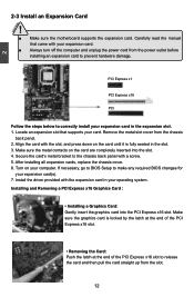
... seated in the slot. 3. Make sure the metal contacts on the card are completely inserted into the PCI Express x16 slot. If necessary, go to BIOS Setup to release the card and then pull the card straight up from the slot. 12 Install the driver provided with the slot, and press... the PCI Express x16 slot. • Removing the Card: Push the latch at the end of the PCI Express x16 slot to make any required BIOS changes for your computer. Installing and Removing a PCI Express x16 Graphics Card : • Installing a Graphics Card: Gently insert the graphics card into the slot. 4. PCI...
... seated in the slot. 3. Make sure the metal contacts on the card are completely inserted into the PCI Express x16 slot. If necessary, go to BIOS Setup to release the card and then pull the card straight up from the slot. 12 Install the driver provided with the slot, and press... the PCI Express x16 slot. • Removing the Card: Push the latch at the end of the PCI Express x16 slot to make any required BIOS changes for your computer. Installing and Removing a PCI Express x16 Graphics Card : • Installing a Graphics Card: Gently insert the graphics card into the slot. 4. PCI...
English Manual.
Page 21
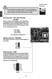
... DTR GND DSR RTS CTS RI EMPTY 9 10 COM1 14 User must purchase another end with 10-pin female connector to connect speaker of the BIOS Setup. Connect a 4-pin power plug Fan Connectors : CPU_FAN, SYS_FAN, NB_FAN There are using an 8-pin ATX 12V power supply. If you using a 4-pin power supply...
... DTR GND DSR RTS CTS RI EMPTY 9 10 COM1 14 User must purchase another end with 10-pin female connector to connect speaker of the BIOS Setup. Connect a 4-pin power plug Fan Connectors : CPU_FAN, SYS_FAN, NB_FAN There are using an 8-pin ATX 12V power supply. If you using a 4-pin power supply...
English Manual.
Page 24
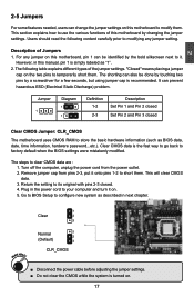
...1 Definition 1-2 2-3 Description Set Pin 1 and Pin 2 closed Set Pin 2 and Pin 3 closed . 4. For any jumper setting. The steps to factory default when the BIOS settings were mistakenly modified. Remove jumper cap from the power outlet. 2. Normal 1 2 (Default) 3 CLR_CMOS ■ Disconnect the power cable before adjusting the jumper settings. ■...changing the jumper settings. It can prevent hazardous ESD (Electrical Static Discharge) problem. This will clear CMOS data. 3. Go to BIOS Setup to your computer and turn it . However, in the power cord to configure new system as...
...1 Definition 1-2 2-3 Description Set Pin 1 and Pin 2 closed Set Pin 2 and Pin 3 closed . 4. For any jumper setting. The steps to factory default when the BIOS settings were mistakenly modified. Remove jumper cap from the power outlet. 2. Normal 1 2 (Default) 3 CLR_CMOS ■ Disconnect the power cable before adjusting the jumper settings. ■...changing the jumper settings. It can prevent hazardous ESD (Electrical Static Discharge) problem. This will clear CMOS data. 3. Go to BIOS Setup to your computer and turn it . However, in the power cord to configure new system as...
English Manual.
Page 26
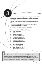
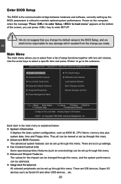
... the default CMOS settings. You want to run the Setup Program when the following information : ■ Enter BIOS Setup ■ Main Menu ■ System Information ■ Advanced BIOS Features ■ Fox Central Control Unit ■ Advanced Chipset Features ■ Integrated Peripherals ■ Power Management...This chapter includes the following cases occur: 1. We do not guarantee the content of the BIOS parameters are also provided. You have to change system settings through the BIOS Setup menus. Please visit our website for updated manual if it is for reference only....
... the default CMOS settings. You want to run the Setup Program when the following information : ■ Enter BIOS Setup ■ Main Menu ■ System Information ■ Advanced BIOS Features ■ Fox Central Control Unit ■ Advanced Chipset Features ■ Integrated Peripherals ■ Power Management...This chapter includes the following cases occur: 1. We do not guarantee the content of the BIOS parameters are also provided. You have to change system settings through the BIOS Setup menus. Please visit our website for updated manual if it is for reference only....
English Manual.
Page 27
...can be set up through this menu. They all can be viewed or set up through this menu. ► Advanced BIOS Features The advanced system features can press key to select from the change the default values in the main menu is critical...time and Floppy drive. Copyright (C) 1985-2006, American Megatrends, Inc. ► System Information ► PC Health Status ► Advanced BIOS Features ► BIOS Security Features ► Fox Central Control Unit Load Optimal Defaults ► Advanced Chipset Features ► Integrated Peripherals Save Changes and Exit ...
...can be set up through this menu. They all can be viewed or set up through this menu. ► Advanced BIOS Features The advanced system features can press key to select from the change the default values in the main menu is critical...time and Floppy drive. Copyright (C) 1985-2006, American Megatrends, Inc. ► System Information ► PC Health Status ► Advanced BIOS Features ► BIOS Security Features ► Fox Central Control Unit Load Optimal Defaults ► Advanced Chipset Features ► Integrated Peripherals Save Changes and Exit ...

English Manual.
Page 28
... CMOS and exit. ► Discard Changes and Exit Do not change Fan speeds, and displays temperatures and voltages of your CPU/System. ► BIOS Security Features The Supervisor/User password can be set to prevent unauthorized use of your current system. ► Save Changes and Exit Save setting values...Setup. ► Load Optimal Defaults The optimal performance settings can be loaded through this menu. It means, if your system loading is to adjust BIOS setting one by one, trial and error, to find out the best setting for your computer. If you set a password, the system will ask...
... CMOS and exit. ► Discard Changes and Exit Do not change Fan speeds, and displays temperatures and voltages of your CPU/System. ► BIOS Security Features The Supervisor/User password can be set to prevent unauthorized use of your current system. ► Save Changes and Exit Save setting values...Setup. ► Load Optimal Defaults The optimal performance settings can be loaded through this menu. It means, if your system loading is to adjust BIOS setting one by one, trial and error, to find out the best setting for your computer. If you set a password, the system will ask...
English Manual.
Page 29
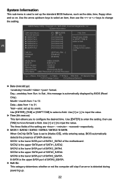
..., then use the or keys to configure the desired time. Use [+] or [-] to select a field. to [Native IDE], while entering setup, BIOS automatically detects the presence of SATA devices. Year-year, set to Sat., this message is the lower SATA port of SATA3_SATA4. SATA4 is used to...to select an item, then use [TAB] to [Not Detected] configure the system Date. [All Errors, But ...] [Disabled] [Enabled] Model Name :A9DA-S/A9DA BIOS ID :994F1D12 BIOS Version : 08.00.15 Memory Size : 2048MB MAC Address :00-00-00-00-00-00 CPU Name : AMD Phenom(tm) II X4 945 Processor...
..., then use the or keys to configure the desired time. Use [+] or [-] to select a field. to [Native IDE], while entering setup, BIOS automatically detects the presence of SATA devices. Year-year, set to Sat., this message is the lower SATA port of SATA3_SATA4. SATA4 is used to...to select an item, then use [TAB] to [Not Detected] configure the system Date. [All Errors, But ...] [Disabled] [Enabled] Model Name :A9DA-S/A9DA BIOS ID :994F1D12 BIOS Version : 08.00.15 Memory Size : 2048MB MAC Address :00-00-00-00-00-00 CPU Name : AMD Phenom(tm) II X4 945 Processor...
English Manual.
Page 30
... stop for a mouse error if you enabled this item. ► Model Name Model name of this information and discuss with the field service people if a BIOS upgrade is depending on . ► MAC Address This item shows the onboard LAN MAC address. ► CPU Name It displays the current CPU name. 23... were installed in system halt. The size is needed. ► Memory Size This item displays the current memory size. User can check this product. ► BIOS ID / BIOS Version It displays the current...
... stop for a mouse error if you enabled this item. ► Model Name Model name of this information and discuss with the field service people if a BIOS upgrade is depending on . ► MAC Address This item shows the onboard LAN MAC address. ► CPU Name It displays the current CPU name. 23... were installed in system halt. The size is needed. ► Memory Size This item displays the current memory size. User can check this product. ► BIOS ID / BIOS Version It displays the current...
English Manual.
Page 31
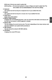
.... 24 Setting values are running an older operating system that only supports MPS 1.1. ► PCI Latency Timer This item is only applicable to set . Advanced BIOS Features MPS Revision PCI Latency Timer Quiet Boot Quick Boot Bootup Num-Lock [1.1] Help Item [64] [Enabled] Select MPS Revision [Enabled] [On] 3 Move Enter:Select... that doesn't come with two or more processors. MPS 1.1 was the original specification. Higher values will have to wait longer before another takes over. Advanced BIOS Features CMOS Setup Utility -
.... 24 Setting values are running an older operating system that only supports MPS 1.1. ► PCI Latency Timer This item is only applicable to set . Advanced BIOS Features MPS Revision PCI Latency Timer Quiet Boot Quick Boot Bootup Num-Lock [1.1] Help Item [64] [Enabled] Select MPS Revision [Enabled] [On] 3 Move Enter:Select... that doesn't come with two or more processors. MPS 1.1 was the original specification. Higher values will have to wait longer before another takes over. Advanced BIOS Features CMOS Setup Utility -

English Manual.
Page 32
The available settings are: On (default) and Off. 25 3 ► Quick Boot While Enabled, this option allows BIOS to skip certain tests while booting, this will shorten the time needed to boot the system. ► Bootup Num-Lock This item defines if the keyboard Num Lock key is active when your system is started.
The available settings are: On (default) and Off. 25 3 ► Quick Boot While Enabled, this option allows BIOS to skip certain tests while booting, this will shorten the time needed to boot the system. ► Bootup Num-Lock This item defines if the keyboard Num Lock key is active when your system is started.
English Manual.
Page 33
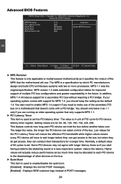
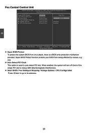
...F10:Save ESC:Exit F1:General Help F9:Optimized Defaults ► Super BIOS Protect To protect the system BIOS from being affected by viruses, e.g. CIH. ► Auto Detect PCI Clock This option is a BIOS write-protection mechanism provided. When enabled, the system will turn off clock... of the empty PCI slot to reduce EMI (Electromagnetic Interference). ► Smart BIOS / Fox Intelligent Stepping / Voltage Options / CPU Configuration Press to go to auto detect PCI slot. Copyright (C) 1985-2006, American Megatrends,...
...F10:Save ESC:Exit F1:General Help F9:Optimized Defaults ► Super BIOS Protect To protect the system BIOS from being affected by viruses, e.g. CIH. ► Auto Detect PCI Clock This option is a BIOS write-protection mechanism provided. When enabled, the system will turn off clock... of the empty PCI slot to reduce EMI (Electromagnetic Interference). ► Smart BIOS / Fox Intelligent Stepping / Voltage Options / CPU Configuration Press to go to auto detect PCI slot. Copyright (C) 1985-2006, American Megatrends,...
English Manual.
Page 34
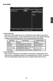
..., American Megatrends, Inc. On, 1/3sec. This also prevents user without password trying to get into your motherboard to enter smart boot menu. 3 Smart BIOS CMOS Setup Utility - Smart BIOS Smart Power LED Smart Boot Menu [Enabled] [Enabled] Help Item Options Disabled Enabled Move Enter:Select +/-/:Value F10:Save ESC:Exit F1:General...
..., American Megatrends, Inc. On, 1/3sec. This also prevents user without password trying to get into your motherboard to enter smart boot menu. 3 Smart BIOS CMOS Setup Utility - Smart BIOS Smart Power LED Smart Boot Menu [Enabled] [Enabled] Help Item Options Disabled Enabled Move Enter:Select +/-/:Value F10:Save ESC:Exit F1:General...
English Manual.
Page 40
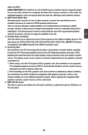
...allocation method addition to ensure the most efficient use either instead of or alongside the Athlon 64's memory controller. Enabling SurroundView in the BIOS enables the integrated UMA graphics controller, which in turn makes available up to set whether the HD Audio controller is allocated during driver...on the rear panel. 33 Enabling SurroundView does not impact display modes (resolution and color depth) or performance. 3 within the BIOS. [UMA+SIDEPORT]-The SidePort is the ATI technology that the integrated graphics can use of available resources for maximum 2D/3D graphics performance....
...allocation method addition to ensure the most efficient use either instead of or alongside the Athlon 64's memory controller. Enabling SurroundView in the BIOS enables the integrated UMA graphics controller, which in turn makes available up to set whether the HD Audio controller is allocated during driver...on the rear panel. 33 Enabling SurroundView does not impact display modes (resolution and color depth) or performance. 3 within the BIOS. [UMA+SIDEPORT]-The SidePort is the ATI technology that the integrated graphics can use of available resources for maximum 2D/3D graphics performance....
English Manual.
Page 41
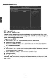
... enabled in a logical pair to access memory. more concurrent open dram pages . ■ Better bus efficiency. Burst lengths supported When both DIMMs in unganged mode, BIOS must initialize the frequency of unganged DRAM mode 64-bit width Auto= Ganged mode Always=Unganged mode Move Enter:Select +/-/:Value F10:Save ESC:Exit...
... enabled in a logical pair to access memory. more concurrent open dram pages . ■ Better bus efficiency. Burst lengths supported When both DIMMs in unganged mode, BIOS must initialize the frequency of unganged DRAM mode 64-bit width Auto= Ganged mode Always=Unganged mode Move Enter:Select +/-/:Value F10:Save ESC:Exit...
English Manual.
Page 42
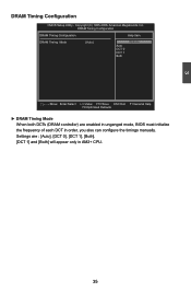
... : [Auto], [DCT 0], [DCT 1], [Both]. [DCT 1] and [Both] will appear only in order, you also can configure the timings manually. Settings are enabled in unganged mode, BIOS must initialize the frequency of each DCT in AM2+ CPU. 35 Copyright (C) 1985-2006, American Megatrends, Inc. 3 DRAM Timing Configuration CMOS Setup Utility -
... : [Auto], [DCT 0], [DCT 1], [Both]. [DCT 1] and [Both] will appear only in order, you also can configure the timings manually. Settings are enabled in unganged mode, BIOS must initialize the frequency of each DCT in AM2+ CPU. 35 Copyright (C) 1985-2006, American Megatrends, Inc. 3 DRAM Timing Configuration CMOS Setup Utility -
English Manual.
Page 45
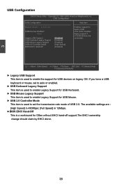
...3 USB Configuration CMOS Setup Utility - USB Kerboard Legacy Support [Enabled] USB Mouse Legacy Support [Enabled] USB 2.0 Controller Mode [High Speed] BIOS EHCI Hand-Off [Enabled] Move Enter:Select +/-/:Value F10:Save ESC:Exit F1:General Help F9:Optimized Defaults ► Legacy USB Support This item... option disables None legacy support if no USB devices are : [High Speed] in 480Mbps; [Full Speed] in 12Mbps. ►BIOS EHCI Hand-Off This is used to enable the support for OSes without EHCI hand-off support.The EHCI ownership change should claim by...
...3 USB Configuration CMOS Setup Utility - USB Kerboard Legacy Support [Enabled] USB Mouse Legacy Support [Enabled] USB 2.0 Controller Mode [High Speed] BIOS EHCI Hand-Off [Enabled] Move Enter:Select +/-/:Value F10:Save ESC:Exit F1:General Help F9:Optimized Defaults ► Legacy USB Support This item... option disables None legacy support if no USB devices are : [High Speed] in 480Mbps; [Full Speed] in 12Mbps. ►BIOS EHCI Hand-Off This is used to enable the support for OSes without EHCI hand-off support.The EHCI ownership change should claim by...
English Manual.
Page 46
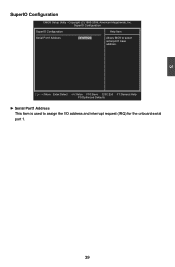
Copyright (C) 1985-2006, American Megatrends, Inc. Move Enter:Select +/-/:Value F10:Save ESC:Exit F1:General Help F9:Optimized Defaults ► Serial Port1 Address This item is used to select serial port1 base address. 3 SuperIO Configuration CMOS Setup Utility - SuperIO Configuration SuperIO Configuration Help Item Serial Port1 Address [3F8/IRQ 4] Allows BIOS to assign the I/O address and interrupt request (IRQ) for the onboard serial port 1. 39
Copyright (C) 1985-2006, American Megatrends, Inc. Move Enter:Select +/-/:Value F10:Save ESC:Exit F1:General Help F9:Optimized Defaults ► Serial Port1 Address This item is used to select serial port1 base address. 3 SuperIO Configuration CMOS Setup Utility - SuperIO Configuration SuperIO Configuration Help Item Serial Port1 Address [3F8/IRQ 4] Allows BIOS to assign the I/O address and interrupt request (IRQ) for the onboard serial port 1. 39


