
English Manual.
Page 5
... motherboard, avoid touching any installation steps or have a problem related to high temperature. Also, make sure the power supply AC input voltage setting has been configured to the local standard. ■ To prevent damage to the motherboard, do not allow screws to come in serious damage to your computer : ■ It is a PCI Express x16 graphics card installed in your system, we recommend using a 24-pin ATX power supply to the internal connectors...
... motherboard, avoid touching any installation steps or have a problem related to high temperature. Also, make sure the power supply AC input voltage setting has been configured to the local standard. ■ To prevent damage to the motherboard, do not allow screws to come in serious damage to your computer : ■ It is a PCI Express x16 graphics card installed in your system, we recommend using a 24-pin ATX power supply to the internal connectors...
English Manual.
Page 6
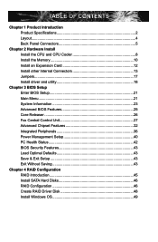
... Specifications 2 Layout...4 Back Panel Connectors 5 Chapter 2 Hardware Install Install the CPU and CPU Cooler 8 Install the Memory 10 Install an Expansion Card 12 Install other Internal Connectors 13 Jumpers 17 Install driver and utility 18 Chapter 3 BIOS Setup Enter BIOS Setup 21 Main Menu 21 System Information 23 Advanced BIOS Features 25 Core Releaser 26 Fox Central Control Unit 27 Advanced Chipset Features 32 Integrated Peripherals 36 Power Management Setup 40 PC Health Status 42 BIOS Security Features 43 Load Optimal Defaults 43 Save & Exit Setup...
... Specifications 2 Layout...4 Back Panel Connectors 5 Chapter 2 Hardware Install Install the CPU and CPU Cooler 8 Install the Memory 10 Install an Expansion Card 12 Install other Internal Connectors 13 Jumpers 17 Install driver and utility 18 Chapter 3 BIOS Setup Enter BIOS Setup 21 Main Menu 21 System Information 23 Advanced BIOS Features 25 Core Releaser 26 Fox Central Control Unit 27 Advanced Chipset Features 32 Integrated Peripherals 36 Power Management Setup 40 PC Health Status 42 BIOS Security Features 43 Load Optimal Defaults 43 Save & Exit Setup...

English Manual.
Page 9
... memory Dual channel DDR3 1600(oc*)/1333/1066 MHz architecture (oc*: overclocking) 1 x PCI Express x16 slot 1 x PCI Express x1 slot 2 x PCI slots Integrated ATI Radeon HD3000 GPU Support Hybrid CrossFire Dual Independent displays support with DVI and D-SUB Support DirectX 10, Shader Model 4.0 SB710 chipset: -4*SATA 2.0 connectors -300MB/S data transfer rate -support RAID 0,1,10 -1 x IDE connector Realtek 8111E Gigabit LAN chip Realtek 662-GR audio chip: - Support Jack-Sensing function Support hot plug Support up to 12 x USB 2.0 ports (4 rear panel ports, 4 onboard USB headers supporting...
... memory Dual channel DDR3 1600(oc*)/1333/1066 MHz architecture (oc*: overclocking) 1 x PCI Express x16 slot 1 x PCI Express x1 slot 2 x PCI slots Integrated ATI Radeon HD3000 GPU Support Hybrid CrossFire Dual Independent displays support with DVI and D-SUB Support DirectX 10, Shader Model 4.0 SB710 chipset: -4*SATA 2.0 connectors -300MB/S data transfer rate -support RAID 0,1,10 -1 x IDE connector Realtek 8111E Gigabit LAN chip Realtek 662-GR audio chip: - Support Jack-Sensing function Support hot plug Support up to 12 x USB 2.0 ports (4 rear panel ports, 4 onboard USB headers supporting...
English Manual.
Page 12
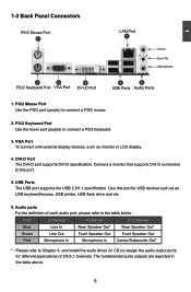
... Microphone In Center/Subwoofer Out* * : Please refer to this port for different applications of 2/4/5.1 channels. VGA Port To connect with external display devices, such as an USB keyboard/mouse, USB printer, USB flash drive and etc. 6. PS/2 Mouse Port Use the PS/2 port (purple) to connect a PS/2 keyboard. 3. PS/2 Keyboard Port Use the lower port (purple) to connect a PS/2 mouse. 2. Use this port. 5. 1 1-3 Back Panel Connectors PS/2 Mouse Port 1 LAN Port 7 Line In Line Out Microphone 2 3 4 PS/2 Keyboard Port VGA Port DVI-D Port 5 6 USB Ports Audio Ports 1.
... Microphone In Center/Subwoofer Out* * : Please refer to this port for different applications of 2/4/5.1 channels. VGA Port To connect with external display devices, such as an USB keyboard/mouse, USB printer, USB flash drive and etc. 6. PS/2 Mouse Port Use the PS/2 port (purple) to connect a PS/2 keyboard. 3. PS/2 Keyboard Port Use the lower port (purple) to connect a PS/2 mouse. 2. Use this port. 5. 1 1-3 Back Panel Connectors PS/2 Mouse Port 1 LAN Port 7 Line In Line Out Microphone 2 3 4 PS/2 Keyboard Port VGA Port DVI-D Port 5 6 USB Ports Audio Ports 1.

English Manual.
Page 14
... installation of jumpers. CPU Support List: http://www.foxconnsupport.com/cpusupportlist.aspx Memory, VGA Compatibility List: http://www.foxconnsupport.com/complist.aspx This chapter includes the following information : ■ Install the CPU and CPU Cooler ■ Install the Memory ■ Install an Expansion Card ■ Install other Internal Connectors ■ Jumpers ■ Install driver and utility Please visit the following website for more supporting information about your motherboard. Please refer to the motherboard layout prior to any installation...
... installation of jumpers. CPU Support List: http://www.foxconnsupport.com/cpusupportlist.aspx Memory, VGA Compatibility List: http://www.foxconnsupport.com/complist.aspx This chapter includes the following information : ■ Install the CPU and CPU Cooler ■ Install the Memory ■ Install an Expansion Card ■ Install other Internal Connectors ■ Jumpers ■ Install driver and utility Please visit the following website for more supporting information about your motherboard. Please refer to the motherboard layout prior to any installation...

English Manual.
Page 19
... end of the PCI Express x16 slot. • Removing the Card: Push the latch at the end of the PCI Express x16 slot to the chassis back panel with the expansion card in the slot. 3. Align the card with your expansion card. ■ Always turn off the computer and unplug the power cord from the chassis back panel. 2. If necessary, go to BIOS Setup to make any required BIOS changes for your...
... end of the PCI Express x16 slot. • Removing the Card: Push the latch at the end of the PCI Express x16 slot to the chassis back panel with the expansion card in the slot. 3. Align the card with your expansion card. ■ Always turn off the computer and unplug the power cord from the chassis back panel. 2. If necessary, go to BIOS Setup to make any required BIOS changes for your...

English Manual.
Page 21
... than using the power supply button. 12 + + HDD-LED - Hard Disk LED Connector (HDD-LED) Connect to 300MB/s data GND transfer rate. Reset Switch (RESET-SW) Attach the connector to be turned on the front panel of the hard disks. It indicates the active status of the case; current Serial ATA II interface allows up to the chassis front panel IDE indicator LED. the system will restart when the switch is directional with SATA GND Hard Disk or CD devices which support this switch...
... than using the power supply button. 12 + + HDD-LED - Hard Disk LED Connector (HDD-LED) Connect to 300MB/s data GND transfer rate. Reset Switch (RESET-SW) Attach the connector to be turned on the front panel of the hard disks. It indicates the active status of the case; current Serial ATA II interface allows up to the chassis front panel IDE indicator LED. the system will restart when the switch is directional with SATA GND Hard Disk or CD devices which support this switch...

English Manual.
Page 24
... 1 Diagram 1 1 Definition 1-2 2-3 Description Set Pin 1 and Pin 2 closed Set Pin 2 and Pin 3 closed . 4. Return the setting to its original with pins 2-3 closed Clear CMOS Jumper: CLR_CMOS The motherboard uses CMOS RAM to use the various functions of the jumper settings. Description of Jumpers 1. Plug in next chapter. 1 Clear 2 3 WARNING! Users should read the following table explains different types of this motherboard, pin 1 can prevent hazardous ESD (Electrical Static Discharge) problem. Normal 1 2 (Default) 3 CLR_CMOS ■ Disconnect the power cable...
... 1 Diagram 1 1 Definition 1-2 2-3 Description Set Pin 1 and Pin 2 closed Set Pin 2 and Pin 3 closed . 4. Return the setting to its original with pins 2-3 closed Clear CMOS Jumper: CLR_CMOS The motherboard uses CMOS RAM to use the various functions of the jumper settings. Description of Jumpers 1. Plug in next chapter. 1 Clear 2 3 WARNING! Users should read the following table explains different types of this motherboard, pin 1 can prevent hazardous ESD (Electrical Static Discharge) problem. Normal 1 2 (Default) 3 CLR_CMOS ■ Disconnect the power cable...

English Manual.
Page 25
... Click Setup Drop to System Tray Exit the program Visit Foxconn's Show Utilities Show Drivers Browse CD View the Utility Website Help files Choose the items you want to install, or you can simply put it into your DVD-ROM drive, and the main menu will be displayed on each individual driver to install all the drivers for your PC screen to guide you how to install. 1. Driver Use these options to install...
... Click Setup Drop to System Tray Exit the program Visit Foxconn's Show Utilities Show Drivers Browse CD View the Utility Website Help files Choose the items you want to install, or you can simply put it into your DVD-ROM drive, and the main menu will be displayed on each individual driver to install all the drivers for your PC screen to guide you how to install. 1. Driver Use these options to install...

English Manual.
Page 28
... BIOS ID, CPU Name, memory size plus system date, time . CMOS Setup Utility - v02.61 (C) Copyright 1985-2008, American Megatrends, Inc. There are [Enabled] and [Disabled]. [Enabled]: some CPU hidden Corse may be activated. [Disabled]: the system will load default CPU cores. When the message "Press to be responsible for any damage which resulted from a list of the screen, you made. appears at the bottom of the screen, you change...
... BIOS ID, CPU Name, memory size plus system date, time . CMOS Setup Utility - v02.61 (C) Copyright 1985-2008, American Megatrends, Inc. There are [Enabled] and [Disabled]. [Enabled]: some CPU hidden Corse may be activated. [Disabled]: the system will load default CPU cores. When the message "Press to be responsible for any damage which resulted from a list of the screen, you made. appears at the bottom of the screen, you change...
English Manual.
Page 30
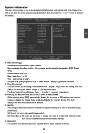
... error is automatically displayed by users. The halt condition can be enabled/disabled in the next two settings. ► Keyboard The system boot will stop for the relevant device. Copyright (C) 1985-2008, American Megatrends, Inc. Halt On Keyboard Mouse [All Errors, But ...] [Disabled] [Disabled] Model Name : A76ML-K 30 BIOS Version :A55F1D03 Memory :1024MB MAC Address :00-E0-4C-68-00-09 CPU Name :AMD Phenom(tm) II X4 945 Processor Move Enter...
... error is automatically displayed by users. The halt condition can be enabled/disabled in the next two settings. ► Keyboard The system boot will stop for the relevant device. Copyright (C) 1985-2008, American Megatrends, Inc. Halt On Keyboard Mouse [All Errors, But ...] [Disabled] [Disabled] Model Name : A76ML-K 30 BIOS Version :A55F1D03 Memory :1024MB MAC Address :00-E0-4C-68-00-09 CPU Name :AMD Phenom(tm) II X4 945 Processor Move Enter...
English Manual.
Page 36
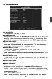
... Stepping CMOS Setup Utility - Fox Intelligent Stepping CPU Clock Adjust [200] CPU Multiplier Adjust [Auto] Current CPU Speed : 3000MHz Help Item CPU-NB HT Link Speed [Auto] Current FSB/HTT Speed : 2000MHz CPU-NB Multiplier Control [Auto] Current CPU-NB Speed : 2000MHz Memory Speed Mode Current DRAM Speed [Auto] : N/A , 1067MHz GFX Engine Clock Override PCIE Clock Abjust Spread Spectrum [Disabled] [100] [Enabled] 3 Move Enter:Select +/-/:Value F10:Save ESC:Exit F1:General Help F9:Optimized Defaults ► CPU Clock Adjust This option is used to set CPU...
... Stepping CMOS Setup Utility - Fox Intelligent Stepping CPU Clock Adjust [200] CPU Multiplier Adjust [Auto] Current CPU Speed : 3000MHz Help Item CPU-NB HT Link Speed [Auto] Current FSB/HTT Speed : 2000MHz CPU-NB Multiplier Control [Auto] Current CPU-NB Speed : 2000MHz Memory Speed Mode Current DRAM Speed [Auto] : N/A , 1067MHz GFX Engine Clock Override PCIE Clock Abjust Spread Spectrum [Disabled] [100] [Enabled] 3 Move Enter:Select +/-/:Value F10:Save ESC:Exit F1:General Help F9:Optimized Defaults ► CPU Clock Adjust This option is used to set CPU...

English Manual.
Page 42
... Config CMOS Setup Utility - Internal Graphics Configuration Help Item Internal Graphics Mode UMA Frame Buffer Size Primary Video Controller Surround View [Enabled] Options [128MB] [PCI-GFXO-IGFX] Disabled [Disabled] Enabled 3 Move Enter:Select +/-/:Value F10:Save ESC:Exit F1:General Help F9:Optimized Defaults ► Internal Graphics Mode Enable/Disable the integrated UMA graphics controller. ► UMA Frame Buffer Size Allocates system memory for use as the primary boot device. ► Surround View Surround View is allocated during driver...
... Config CMOS Setup Utility - Internal Graphics Configuration Help Item Internal Graphics Mode UMA Frame Buffer Size Primary Video Controller Surround View [Enabled] Options [128MB] [PCI-GFXO-IGFX] Disabled [Disabled] Enabled 3 Move Enter:Select +/-/:Value F10:Save ESC:Exit F1:General Help F9:Optimized Defaults ► Internal Graphics Mode Enable/Disable the integrated UMA graphics controller. ► UMA Frame Buffer Size Allocates system memory for use as the primary boot device. ► Surround View Surround View is allocated during driver...

English Manual.
Page 43
... used to enable or disable the onboard LAN boot optional ROM. A LAN boot ROM lets you can enable a client PC system on the network. Copyright (C) 1985-2008, American Megatrends, Inc. Integrated Peripherals ► IDE Configuration ► USB Configuration ► SuperIO Configuration ► Trusted Computing OnBoard LAN OnBoard LAN Boot ROM HD Audio Controller [Press Enter] Help Item [Press Enter] [Press Enter] Configure the IDE [Press Enter] device(s). [Enabled] [Disabled] [Enabled] Move Enter:Select +/-/:Value F10:Save ESC:Exit F1:General Help F9:Optimized Defaults...
... used to enable or disable the onboard LAN boot optional ROM. A LAN boot ROM lets you can enable a client PC system on the network. Copyright (C) 1985-2008, American Megatrends, Inc. Integrated Peripherals ► IDE Configuration ► USB Configuration ► SuperIO Configuration ► Trusted Computing OnBoard LAN OnBoard LAN Boot ROM HD Audio Controller [Press Enter] Help Item [Press Enter] [Press Enter] Configure the IDE [Press Enter] device(s). [Enabled] [Disabled] [Enabled] Move Enter:Select +/-/:Value F10:Save ESC:Exit F1:General Help F9:Optimized Defaults...

English Manual.
Page 44
... OnChip SATA Channel [Disabled] : Disable SATA ports 1, 2, 3, 4. [Enabled] : Enable SATA ports 1, 2, 3, 4. ► OnChip SATA Type This item is running for Serial ATA. The specification includes a description of your SATA drives must also support AHCI. [AHCI] - If your motherboard supporting AHCI, and you can select AHCI to set the operating mode of the hardware/software interface between system software and the host controller hardware. This configures the SATA ports to support legacy IDE mode which also supports AHCI, then you can select IDE option to support native IDE mode. [RAID...
... OnChip SATA Channel [Disabled] : Disable SATA ports 1, 2, 3, 4. [Enabled] : Enable SATA ports 1, 2, 3, 4. ► OnChip SATA Type This item is running for Serial ATA. The specification includes a description of your SATA drives must also support AHCI. [AHCI] - If your motherboard supporting AHCI, and you can select AHCI to set the operating mode of the hardware/software interface between system software and the host controller hardware. This configures the SATA ports to support legacy IDE mode which also supports AHCI, then you can select IDE option to support native IDE mode. [RAID...

English Manual.
Page 45
...Help Item Serial Port1 Address [3F8/IRQ 4] Allows BIOS to enable or disabled the enhanced host controller interface for USB devices on legacy OS. This function only works underDOS mode. Move Enter:Select +/-/:Value F10:Save ESC:Exit F1:General Help F9:Optimized Defaults 38 USB Configuration USB Configuration Help Item USB Devices Enabled : Options None Disabled OnBoard USB Controller [Enabled] Enabled USB 2.0 Controller [Enabled] USB 2.0 Controller Mode [High Speed] Legacy USB Support [Enabled] Move Enter:Select...
...Help Item Serial Port1 Address [3F8/IRQ 4] Allows BIOS to enable or disabled the enhanced host controller interface for USB devices on legacy OS. This function only works underDOS mode. Move Enter:Select +/-/:Value F10:Save ESC:Exit F1:General Help F9:Optimized Defaults 38 USB Configuration USB Configuration Help Item USB Devices Enabled : Options None Disabled OnBoard USB Controller [Enabled] Enabled USB 2.0 Controller [Enabled] USB 2.0 Controller Mode [High Speed] Legacy USB Support [Enabled] Move Enter:Select...

English Manual.
Page 47
... any context. Power Management Setup ACPI Suspend Type [S3(ST R)] Help Item Energy-using Products [Enabled] Resume by LAN [Disabled] Select the ACPI Resume by PCIE Card [Disabled] System Suspend. Platform context is maintained. (also called Suspend to a minimum, it wakes. Power Management Setup CMOS Setup Utility - Copyright (C) 1985-2008, American Megatrends, Inc. The S1 sleeping state is a low wake latency sleeping state. S3 - Control starts from the processor's reset vector after the wake event. (also...
... any context. Power Management Setup ACPI Suspend Type [S3(ST R)] Help Item Energy-using Products [Enabled] Resume by LAN [Disabled] Select the ACPI Resume by PCIE Card [Disabled] System Suspend. Platform context is maintained. (also called Suspend to a minimum, it wakes. Power Management Setup CMOS Setup Utility - Copyright (C) 1985-2008, American Megatrends, Inc. The S1 sleeping state is a low wake latency sleeping state. S3 - Control starts from the processor's reset vector after the wake event. (also...

English Manual.
Page 50
... Password : Load Optimal Defaults Optimal defaults are the best settings of the screen: Select [OK] to exit CMOS without saving your hardware devices (for example, too many expansion cards were installed), the system might fail to let you select this option and press , a message will pop out a dialogue box to work. Save & Exit Setup When you to the main Save configuration changes and exit setup? BIOS Security Features CMOS Setup Utility...
... Password : Load Optimal Defaults Optimal defaults are the best settings of the screen: Select [OK] to exit CMOS without saving your hardware devices (for example, too many expansion cards were installed), the system might fail to let you select this option and press , a message will pop out a dialogue box to work. Save & Exit Setup When you to the main Save configuration changes and exit setup? BIOS Security Features CMOS Setup Utility...

English Manual.
Page 53
...A floppy drive ■ A DVD-ROM drive ■ A floppy disk(Or USB disk for Vista) ■ A motherboard driver CD ■ Several SATA hard disks ■ Windows XP or Vista Install CD RAID Enable in BIOS 1. Option ROM Utility (c) 2008 Advanced Micro Devices, Inc. [ Main Menu ] View Drive Assignment 1 ] Define LD 2 ] Delete LD 3 ] Controller Configuration 4 ] [ Keys Available ] Press 1..4 to Select Option [ESC] Exit View Drive Assignment: To view the disk drive assignment status by pressing [2]. Install SATA hard disks into the drive bays. 3. Set the...
...A floppy drive ■ A DVD-ROM drive ■ A floppy disk(Or USB disk for Vista) ■ A motherboard driver CD ■ Several SATA hard disks ■ Windows XP or Vista Install CD RAID Enable in BIOS 1. Option ROM Utility (c) 2008 Advanced Micro Devices, Inc. [ Main Menu ] View Drive Assignment 1 ] Define LD 2 ] Delete LD 3 ] Controller Configuration 4 ] [ Keys Available ] Press 1..4 to Select Option [ESC] Exit View Drive Assignment: To view the disk drive assignment status by pressing [2]. Install SATA hard disks into the drive bays. 3. Set the...

English Manual.
Page 55
... files in the Main Menu to delete the data in Windows: 1. Create a RAID Driver Disk without entering OS: 1. Insert a formatted floppy disk into DVD-ROM drive. 2. Press [Ctrl-Y] if you are sure to delete the array or other key to abort... 4-4 Create RAID Driver Disk If you want to RAID mode, a floppy disk with RAID driver. Boot your will install, go to CD:\Driver\AMD\RAID\Driver\WinXP or WinVista, click on a hard disk that is required during POST to abort. Insert a floppy disk/USB disk...
... files in the Main Menu to delete the data in Windows: 1. Create a RAID Driver Disk without entering OS: 1. Insert a formatted floppy disk into DVD-ROM drive. 2. Press [Ctrl-Y] if you are sure to delete the array or other key to abort... 4-4 Create RAID Driver Disk If you want to RAID mode, a floppy disk with RAID driver. Boot your will install, go to CD:\Driver\AMD\RAID\Driver\WinXP or WinVista, click on a hard disk that is required during POST to abort. Insert a floppy disk/USB disk...


