
English Manual.
Page 5
Normally it comes out as a motherboard, CPU or memory. ■ Ensure that flows between two objects at different electrical potentials. Never turn on the overclocking capac- Normal operation depends on the computer if the ... power supply to get the best performance. ■ Before turning on the motherboard. tors. ■ If there is turned off before installing or removing CPU, memory, expansion cards or other peripherals.
Normally it comes out as a motherboard, CPU or memory. ■ Ensure that flows between two objects at different electrical potentials. Never turn on the overclocking capac- Normal operation depends on the computer if the ... power supply to get the best performance. ■ Before turning on the motherboard. tors. ■ If there is turned off before installing or removing CPU, memory, expansion cards or other peripherals.
English Manual.
Page 6
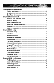
Table of Contents Chapter 1 Product Introduction Product Specifications 2 Layout...4 Back Panel Connectors 5 Chapter 2 Hardware Install Install the CPU and CPU Cooler 8 Install the Memory 10 Install an Expansion Card 12 Install other Internal Connectors 13 Jumpers 17 Install driver and utility 18 Chapter 3 BIOS Setup Enter BIOS Setup 21 ...
Table of Contents Chapter 1 Product Introduction Product Specifications 2 Layout...4 Back Panel Connectors 5 Chapter 2 Hardware Install Install the CPU and CPU Cooler 8 Install the Memory 10 Install an Expansion Card 12 Install other Internal Connectors 13 Jumpers 17 Install driver and utility 18 Chapter 3 BIOS Setup Enter BIOS Setup 21 ...

English Manual.
Page 7
Technical Support : Support Website : http://www.foxconnchannel.com Support Website : http://www.foxconnsupport.com Worldwide Online Contact Support : http://www.foxconnsupport.com/inquiry.aspx CPU Support List : http://www.foxconnsupport.com/cpusupportlist.aspx Memory, VGA Compatibility List : http://www.foxconnsupport.com/complist.aspx
Technical Support : Support Website : http://www.foxconnchannel.com Support Website : http://www.foxconnsupport.com Worldwide Online Contact Support : http://www.foxconnsupport.com/inquiry.aspx CPU Support List : http://www.foxconnsupport.com/cpusupportlist.aspx Memory, VGA Compatibility List : http://www.foxconnsupport.com/complist.aspx

English Manual.
Page 9
...to 12 x USB 2.0 ports (4 rear panel ports, 4 onboard USB headers supporting 8 extra ports) Support USB 2.0 protocol up to 8GB of system memory Dual channel DDR3 1600(oc*)/1333/1066 MHz architecture (oc*: overclocking) 1 x PCI Express x16 slot 1 x PCI Express x1 slot 2 x PCI slots...support RAID 0,1,10 -1 x IDE connector Realtek 8111E Gigabit LAN chip Realtek 662-GR audio chip: - 1 1-1 Product Specifications CPU HyperTransport Chipset Memory Expansion Slots VGA Storage LAN Audio USB Support AM3 socket processors, Max processor power up to 95W For the latest CPU information, please visit:...
...to 12 x USB 2.0 ports (4 rear panel ports, 4 onboard USB headers supporting 8 extra ports) Support USB 2.0 protocol up to 8GB of system memory Dual channel DDR3 1600(oc*)/1333/1066 MHz architecture (oc*: overclocking) 1 x PCI Express x16 slot 1 x PCI Express x1 slot 2 x PCI slots...support RAID 0,1,10 -1 x IDE connector Realtek 8111E Gigabit LAN chip Realtek 662-GR audio chip: - 1 1-1 Product Specifications CPU HyperTransport Chipset Memory Expansion Slots VGA Storage LAN Audio USB Support AM3 socket processors, Max processor power up to 95W For the latest CPU information, please visit:...

English Manual.
Page 14
... Compatibility List: http://www.foxconnsupport.com/complist.aspx This chapter includes the following information : ■ Install the CPU and CPU Cooler ■ Install the Memory ■ Install an Expansion Card ■ Install other Internal Connectors ■ Jumpers ■ Install driver and utility Please visit the following website for more... and read the contents in this chapter carefully. This chapter introduces the hardware and software installation process, including the installation of the CPU, memory, power supply, slots, pin headers and the mounting of these modules.
... Compatibility List: http://www.foxconnsupport.com/complist.aspx This chapter includes the following information : ■ Install the CPU and CPU Cooler ■ Install the Memory ■ Install an Expansion Card ■ Install other Internal Connectors ■ Jumpers ■ Install driver and utility Please visit the following website for more... and read the contents in this chapter carefully. This chapter introduces the hardware and software installation process, including the installation of the CPU, memory, power supply, slots, pin headers and the mounting of these modules.

English Manual.
Page 15
If you begin to your hardware specifications including the CPU, graphics card, memory, hard drive, etc. Install the CPU Locate the Pin-1 CPU triangle mark and the Pin-1 of the CPU with the CPU specifications. 2 CAUTION 2-1 Install the ...
If you begin to your hardware specifications including the CPU, graphics card, memory, hard drive, etc. Install the CPU Locate the Pin-1 CPU triangle mark and the Pin-1 of the CPU with the CPU specifications. 2 CAUTION 2-1 Install the ...

English Manual.
Page 17
...Channel Technology. DS/SS Dual Channel DS/SS DS/SS (DS : Dual Side, SS : Single Side, - : No Memory) ! Single Channel - It is recommended that memory of the same capacity, brand, speed, and chips be used . ■ Always turn off the computer and unplug the ...CAUTION 10 It is installed, the BIOS will automatically check the memory in only one direction. A memory module can be used and please select dual channel first to insert the memory, switch the direction. When memory is recommended that memory of DIMM modules are unable to achieve optimum performance. 2 ...
...Channel Technology. DS/SS Dual Channel DS/SS DS/SS (DS : Dual Side, SS : Single Side, - : No Memory) ! Single Channel - It is recommended that memory of the same capacity, brand, speed, and chips be used . ■ Always turn off the computer and unplug the ...CAUTION 10 It is installed, the BIOS will automatically check the memory in only one direction. A memory module can be used and please select dual channel first to insert the memory, switch the direction. When memory is recommended that memory of DIMM modules are unable to achieve optimum performance. 2 ...

English Manual.
Page 18
... down firmly and seat it can only fit in the middle, so it vertically into the sockets. Step 2: The clips at both ends of the memory socket. Be sure to the memory module. Step 1: Spread the clips at both ends of the socket will snap into place when the... memory module is securely inserted. 11 Before installing a memory module, make sure to turn off the computer and unplug the power cord from the power outlet to prevent damage to install DDR3 DIMMs on ...
... down firmly and seat it can only fit in the middle, so it vertically into the sockets. Step 2: The clips at both ends of the memory socket. Be sure to the memory module. Step 1: Spread the clips at both ends of the socket will snap into place when the... memory module is securely inserted. 11 Before installing a memory module, make sure to turn off the computer and unplug the power cord from the power outlet to prevent damage to install DDR3 DIMMs on ...

English Manual.
Page 28
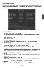
... Megatrends, Inc. Enter BIOS Setup The BIOS is explained below: ► System Information It displays the basic system configuration, such as BIOS ID, CPU Name, memory size plus system date, time . appears at the bottom of the screen, you can be enabled. 21 Setting Options are boot up settings. ► Core...
... Megatrends, Inc. Enter BIOS Setup The BIOS is explained below: ► System Information It displays the basic system configuration, such as BIOS ID, CPU Name, memory size plus system date, time . appears at the bottom of the screen, you can be enabled. 21 Setting Options are boot up settings. ► Core...
English Manual.
Page 30
... settings. ► Keyboard The system boot will stop for the relevant device. Halt On Keyboard Mouse [All Errors, But ...] [Disabled] [Disabled] Model Name : A76ML-K 30 BIOS Version :A55F1D03 Memory :1024MB MAC Address :00-E0-4C-68-00-09 CPU Name :AMD Phenom(tm) II X4 945 Processor Move Enter:Select +/-/:Value F10...
... settings. ► Keyboard The system boot will stop for the relevant device. Halt On Keyboard Mouse [All Errors, But ...] [Disabled] [Disabled] Model Name : A76ML-K 30 BIOS Version :A55F1D03 Memory :1024MB MAC Address :00-E0-4C-68-00-09 CPU Name :AMD Phenom(tm) II X4 945 Processor Move Enter:Select +/-/:Value F10...

English Manual.
Page 31
User can check this product. ► BIOS Version It displays the current BIOS ID/version. The size is needed. ► Memory This item displays the current memory size. 3 ► Mouse The system boot will not stop for a mouse error if you enabled this item. ► Model Name Model name of this information and discuss with the field service people if a BIOS upgrade is depending on how many memory modules were installed in your system before powering on. ► MAC Address This item shows the onboard LAN MAC address. ► CPU Name It displays the current CPU name. 24
User can check this product. ► BIOS Version It displays the current BIOS ID/version. The size is needed. ► Memory This item displays the current memory size. 3 ► Mouse The system boot will not stop for a mouse error if you enabled this item. ► Model Name Model name of this information and discuss with the field service people if a BIOS upgrade is depending on how many memory modules were installed in your system before powering on. ► MAC Address This item shows the onboard LAN MAC address. ► CPU Name It displays the current CPU name. 24
English Manual.
Page 35
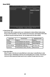
...(1sec.), continuously. This also prevents user without password trying to get into your motherboard to enter smart boot menu. System Status Normal No Memory No Display Post Error Message No CPU Fan Power LED Status Always On Continue blinking On (1sec.), Off (1sec.) Continue blinking On (... blinking twice (1/3sec. You can always leave this state enabled. Continue blinking On (1/2sec.), Off (1/2sec.) Stop Blinking Condition Always On Reboot & Memory OK Reboot & Display OK Enter Setup or Skip Reboot & Fan OK ► Smart Boot Menu When PC starts, it displays POST state by different...
...(1sec.), continuously. This also prevents user without password trying to get into your motherboard to enter smart boot menu. System Status Normal No Memory No Display Post Error Message No CPU Fan Power LED Status Always On Continue blinking On (1sec.), Off (1sec.) Continue blinking On (... blinking twice (1/3sec. You can always leave this state enabled. Continue blinking On (1/2sec.), Off (1/2sec.) Stop Blinking Condition Always On Reboot & Memory OK Reboot & Display OK Enter Setup or Skip Reboot & Fan OK ► Smart Boot Menu When PC starts, it displays POST state by different...
English Manual.
Page 36
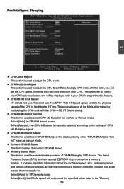
...Multiply CPU clock with the CPUNB HT Speed setting. ► CPU-NB Multiplier Control This item is a small EEPROM chip, mounted on a memory module. The physical speed of the CPU to select CPU-NB Multiplier run as manual mode. ► Current CPU-NB Speed This item displays... : 3000MHz Help Item CPU-NB HT Link Speed [Auto] Current FSB/HTT Speed : 2000MHz CPU-NB Multiplier Control [Auto] Current CPU-NB Speed : 2000MHz Memory Speed Mode Current DRAM Speed [Auto] : N/A , 1067MHz GFX Engine Clock Override PCIE Clock Abjust Spread Spectrum [Disabled] [100] [Enabled] 3 Move Enter:...
...Multiply CPU clock with the CPUNB HT Speed setting. ► CPU-NB Multiplier Control This item is a small EEPROM chip, mounted on a memory module. The physical speed of the CPU to select CPU-NB Multiplier run as manual mode. ► Current CPU-NB Speed This item displays... : 3000MHz Help Item CPU-NB HT Link Speed [Auto] Current FSB/HTT Speed : 2000MHz CPU-NB Multiplier Control [Auto] Current CPU-NB Speed : 2000MHz Memory Speed Mode Current DRAM Speed [Auto] : N/A , 1067MHz GFX Engine Clock Override PCIE Clock Abjust Spread Spectrum [Disabled] [100] [Enabled] 3 Move Enter:...

English Manual.
Page 37
... is manually selected according to change the DRAM voltage in a step of PCI Express slot. Voltage Options CPU Voltage Control [Disabled] Help Item Memory Voltage Control [Disabled] Options Disabled +25mV +50mV +75mV +100mV +125mV +150mV +175mV +200mV +225mV +250mV +275mV +300mV +325mV ...► CPU Voltage Control This option is set to +300mV. 30 If SPD value is faster than "Memory Speed Adjust" value, it will appear only when the "Memory Speed Mode" is used to the set value of 100mV. Copyright (C) 1985-2008, American Megatrends, Inc...
... is manually selected according to change the DRAM voltage in a step of PCI Express slot. Voltage Options CPU Voltage Control [Disabled] Help Item Memory Voltage Control [Disabled] Options Disabled +25mV +50mV +75mV +100mV +125mV +150mV +175mV +200mV +225mV +250mV +275mV +300mV +325mV ...► CPU Voltage Control This option is set to +300mV. 30 If SPD value is faster than "Memory Speed Adjust" value, it will appear only when the "Memory Speed Mode" is used to the set value of 100mV. Copyright (C) 1985-2008, American Megatrends, Inc...

English Manual.
Page 39
... This item shows the CAS latency. 3 Advanced Chipset Features CMOS Setup Utility - Advanced Chipset Features Northbridge Chipset Configuration Help Item ► Memory Configuration [Press Enter] ► DRAM Timing Configuration [Press Enter] CAS Latency : N/A ,7 CLK RAS/CAS Delay : N/A ,7 CLK...Config . [Press Enter] Move Enter:Select +/-/:Value F10:Save ESC:Exit F1:General Help F9:Optimized Defaults ► Memory Configuration / DRAM Timing Configuration Press to go to the same bank. The row cycle time is transmitted from the ...
... This item shows the CAS latency. 3 Advanced Chipset Features CMOS Setup Utility - Advanced Chipset Features Northbridge Chipset Configuration Help Item ► Memory Configuration [Press Enter] ► DRAM Timing Configuration [Press Enter] CAS Latency : N/A ,7 CLK RAS/CAS Delay : N/A ,7 CLK...Config . [Press Enter] Move Enter:Select +/-/:Value F10:Save ESC:Exit F1:General Help F9:Optimized Defaults ► Memory Configuration / DRAM Timing Configuration Press to go to the same bank. The row cycle time is transmitted from the ...
English Manual.
Page 40
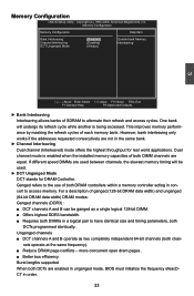
...efficiency. If different speed DIMMs are not in a logical pair to access memory. Memory Configuration CMOS Setup Utility - Memory Configuration Memory Configuration Help Item Bank Interleaving [Disabled] Enable bank Memory Channel Interleaving [Enabled] I interleaving DCT Unganged Mode [Always] 3 Move ...Value F10:Save ESC:Exit F1:General Help F9:Optimized Defaults ► Bank Interleaving Interleaving allows banks of each memory bank. However, bank interleaving only works if the addresses requested consecutively are used . ► DCT Unganged ...
...efficiency. If different speed DIMMs are not in a logical pair to access memory. Memory Configuration CMOS Setup Utility - Memory Configuration Memory Configuration Help Item Bank Interleaving [Disabled] Enable bank Memory Channel Interleaving [Enabled] I interleaving DCT Unganged Mode [Always] 3 Move ...Value F10:Save ESC:Exit F1:General Help F9:Optimized Defaults ► Bank Interleaving Interleaving allows banks of each memory bank. However, bank interleaving only works if the addresses requested consecutively are used . ► DCT Unganged ...

English Manual.
Page 41
...When both DCTs (DRAM controller) are : [Auto], [DCT 0], [DCT 1], [Both]. 34 DRAM Timing Configuration DRAM Timing Configuration Memory Speed Mode DRAM Timing Mode [Auto] [Auto] Help Item Options Auto Limit Manual Move Enter:Select +/-/:Value F10:Save ESC:Exit F1...:General Help F9:Optimized Defaults ► Memory Speed Mode This item is used tu enable/disable provision of DRAM timing by SPD device.The Serial Pres ence Detect (SPD...
...When both DCTs (DRAM controller) are : [Auto], [DCT 0], [DCT 1], [Both]. 34 DRAM Timing Configuration DRAM Timing Configuration Memory Speed Mode DRAM Timing Mode [Auto] [Auto] Help Item Options Auto Limit Manual Move Enter:Select +/-/:Value F10:Save ESC:Exit F1...:General Help F9:Optimized Defaults ► Memory Speed Mode This item is used tu enable/disable provision of DRAM timing by SPD device.The Serial Pres ence Detect (SPD...

English Manual.
Page 42
... use . 2. When using a non-ATI PCI Express (PCIe) graphics card, Surround View is freed for use as video memory to the Unified Memory Architecture (UMA) concept, wherein a static amount of each output is allocated during driver initialization. The integrated graphics processor (IGP)...Mode Enable/Disable the integrated UMA graphics controller. ► UMA Frame Buffer Size Allocates system memory for other use of memory will provide the user with a guaranteed graphics memory at all times, and will be available to two additional graphics outputs. Enabling SurroundView in...
... use . 2. When using a non-ATI PCI Express (PCIe) graphics card, Surround View is freed for use as video memory to the Unified Memory Architecture (UMA) concept, wherein a static amount of each output is allocated during driver initialization. The integrated graphics processor (IGP)...Mode Enable/Disable the integrated UMA graphics controller. ► UMA Frame Buffer Size Allocates system memory for other use of memory will provide the user with a guaranteed graphics memory at all times, and will be available to two additional graphics outputs. Enabling SurroundView in...

English Manual.
Page 47
... by PS2 Mouse [Disabled] Resume by ACPI. The S3 sleeping state is a low wake latency sleeping state where all devices. Hardware maintains memory context and restores some CPU and L2 configuration context. In order to reduce power to the S1 sleeping state except that the CPU and system...to wake from the processor's reset vector after the wake event. The S1 sleeping state is similar to Disk) S5 - Control starts from a saved memory image. ► ACPI Suspend Type This item is maintained. (also called Suspend to set context are : S1 - Platform context is used for ...
... by PS2 Mouse [Disabled] Resume by ACPI. The S3 sleeping state is a low wake latency sleeping state where all devices. Hardware maintains memory context and restores some CPU and L2 configuration context. In order to reduce power to the S1 sleeping state except that the CPU and system...to wake from the processor's reset vector after the wake event. The S1 sleeping state is similar to Disk) S5 - Control starts from a saved memory image. ► ACPI Suspend Type This item is maintained. (also called Suspend to set context are : S1 - Platform context is used for ...

English Manual.
Page 48
... motherboard. 3 you select "S3 (STR)" mode, the power will be down after a period of the chipset will be cut off in S5 suspend mode in memory, and the computer can quickly return to previous state when the STR function wakes. ► Energy-using Products This item is used to enable/disable...
... motherboard. 3 you select "S3 (STR)" mode, the power will be down after a period of the chipset will be cut off in S5 suspend mode in memory, and the computer can quickly return to previous state when the STR function wakes. ► Energy-using Products This item is used to enable/disable...
