Fluke 51II, 52II, 53II, and 54II Thermometer Datasheet
Page 1
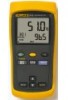
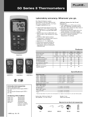
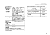
... be easily reviewed on the meter display • IR communication port allows data to be exported to optional FlukeView® Temperature PC software Features Thermocouple types Number of inputs Time stamp Splash/Dust resistant Dual display with backlight Min/Max/Avg recording (T1-T2) True differential Data logging up to 500 points IR data port for interface to PC Compatible with optional FlukeView Software 51 II J,K,T,E Single...
... be easily reviewed on the meter display • IR communication port allows data to be exported to optional FlukeView® Temperature PC software Features Thermocouple types Number of inputs Time stamp Splash/Dust resistant Dual display with backlight Min/Max/Avg recording (T1-T2) True differential Data logging up to 500 points IR data port for interface to PC Compatible with optional FlukeView Software 51 II J,K,T,E Single...

FE 51 & 52 II Users Manual
Page 1
Users Manual Printed in USA All product names are trademarks of their respective companies. ® 51 & 52 Series II Thermometer English September 1999 Rev.1, 6/01 © 1999-2001 Fluke Corporation, All rights reserved.
Users Manual Printed in USA All product names are trademarks of their respective companies. ® 51 & 52 Series II Thermometer English September 1999 Rev.1, 6/01 © 1999-2001 Fluke Corporation, All rights reserved.
FE 51 & 52 II Users Manual
Page 2
... ARE EXPRESSED OR IMPLIED. Box 9090 Everett WA 98206-9090 To register your defective tester to the nearest Fluke Authorized Service Center with a description of the problem. Box 1186 5602 B.D. THIS WARRANTY IS YOUR ONLY REMEDY. Since some states or countries do not allow...THEORY. Limited Warranty & Limitation of Liability This Fluke product will be free from defects in material and workmanship for 3 years from accident, neglect, misuse or abnormal conditions of operation or handling. This warranty does not cover fuses, disposable batteries or damage from the date of purchase.
... ARE EXPRESSED OR IMPLIED. Box 9090 Everett WA 98206-9090 To register your defective tester to the nearest Fluke Authorized Service Center with a description of the problem. Box 1186 5602 B.D. THIS WARRANTY IS YOUR ONLY REMEDY. Since some states or countries do not allow...THEORY. Limited Warranty & Limitation of Liability This Fluke product will be free from defects in material and workmanship for 3 years from accident, neglect, misuse or abnormal conditions of operation or handling. This warranty does not cover fuses, disposable batteries or damage from the date of purchase.
FE 51 & 52 II Users Manual
Page 3
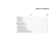
Table of Contents Title Page Introduction ...1 Contacting Fluke ...1 Getting Started...4 Components...5 Display Elements ...6 Buttons...7 Using the Thermometer 9 Changing Setup Options 9 Entering or Exiting Setup 9 Setup Options ...9 Changing a Setup Option 10 Measuring Temperatures 11 Connecting a Thermocouple 11 Displaying Temperatures 11 Holding the Displayed Readings 12 Viewing the MIN, MAX, and AVG Readings 12 Using the Offset to Adjust for Probe Errors 12 i
Table of Contents Title Page Introduction ...1 Contacting Fluke ...1 Getting Started...4 Components...5 Display Elements ...6 Buttons...7 Using the Thermometer 9 Changing Setup Options 9 Entering or Exiting Setup 9 Setup Options ...9 Changing a Setup Option 10 Measuring Temperatures 11 Connecting a Thermocouple 11 Displaying Temperatures 11 Holding the Displayed Readings 12 Viewing the MIN, MAX, and AVG Readings 12 Using the Offset to Adjust for Probe Errors 12 i
FE 51 & 52 II Users Manual
Page 4
51 & 52 Series II Users Manual Maintenance...13 Replacing the Batteries 13 Cleaning the Case and Holster 13 Calibration ...13 Specifications ...13 Environmental...13 General...14 80 PK-1 Thermocouple (supplied with thermometer 14 Electrical...14 Replacement Parts and Accessories 15 ii
51 & 52 Series II Users Manual Maintenance...13 Replacing the Batteries 13 Cleaning the Case and Holster 13 Calibration ...13 Specifications ...13 Environmental...13 General...14 80 PK-1 Thermocouple (supplied with thermometer 14 Electrical...14 Replacement Parts and Accessories 15 ii
FE 51 & 52 II Users Manual
Page 5
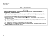
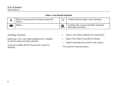
Refer to safety information in Table 1 and meter symbols in Singapore +1-425-446-5500 from other countries Address correspondence to use external J-, K-, T-, and Etype thermocouples (temperature probes) as specified in this manual. P.O. Contacting Fluke To order accessories, receive assistance, or locate the nearest Fluke distributor or Service Center, call: 1-888-99-FLUKE (1-888-993-5853) in USA 1-800-36-FLUKE (1-800-363-5853...
Refer to safety information in Table 1 and meter symbols in Singapore +1-425-446-5500 from other countries Address correspondence to use external J-, K-, T-, and Etype thermocouples (temperature probes) as specified in this manual. P.O. Contacting Fluke To order accessories, receive assistance, or locate the nearest Fluke distributor or Service Center, call: 1-888-99-FLUKE (1-888-993-5853) in USA 1-800-36-FLUKE (1-800-363-5853...
FE 51 & 52 II Users Manual
Page 6
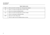
... case. • Replace the batteries as soon as marked on the thermometer, between the thermocouple(s), or between any thermocouple and earth ground. 2 Protection may be impaired. Safety Information WWarning A Warning identifies conditions and actions that pose hazards to personal injury. • Do not use the thermometer if it operates abnormally. 51 & 52 Series II Users Manual Table 1. Do...
... case. • Replace the batteries as soon as marked on the thermometer, between the thermocouple(s), or between any thermocouple and earth ground. 2 Protection may be impaired. Safety Information WWarning A Warning identifies conditions and actions that pose hazards to personal injury. • Do not use the thermometer if it operates abnormally. 51 & 52 Series II Users Manual Table 1. Do...
FE 51 & 52 II Users Manual
Page 7
... potentials greater than 1 V between the thermocouples, use electrically insulated thermocouples. • When servicing the thermometer, use only specified replacement parts. • Do not use the thermometer with the battery case. 3 Safety Information (cont.) WWarning (cont.) • Model 52: Measurement errors may damage the meter or the equipment under test. • Use the proper thermocouples, function, and range for your thermometer. • Do not...
... potentials greater than 1 V between the thermocouples, use electrically insulated thermocouples. • When servicing the thermometer, use only specified replacement parts. • Do not use the thermometer with the battery case. 3 Safety Information (cont.) WWarning (cont.) • Model 52: Measurement errors may damage the meter or the equipment under test. • Use the proper thermocouples, function, and range for your thermometer. • Do not...
FE 51 & 52 II Users Manual
Page 8
... Standards Association directives. Getting Started Everything in this Users Manual applies both to the manual for information about this feature. Battery. International Symbols W M Refer to Models 51 and 52 unless otherwise indicated. Complies with the thermometer, study the following sections. 4 Then read the following : • Figure 1 and Table 3 describe the components. • Figure 2 and Table 4 describe the display. • Table...
... Standards Association directives. Getting Started Everything in this Users Manual applies both to the manual for information about this feature. Battery. International Symbols W M Refer to Models 51 and 52 unless otherwise indicated. Complies with the thermometer, study the following sections. 4 Then read the following : • Figure 1 and Table 3 describe the components. • Figure 2 and Table 4 describe the display. • Table...
FE 51 & 52 II Users Manual
Page 9
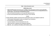
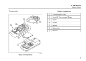
Components aas01f.eps 5 Components A Thermocouple T1 input B Model 52: Thermocouple T2 input C Holster D Display E Buttons F Battery door G Batteries Figure 1. Components 3 4 5 6 7 xx 2 1 51 & 52 Series II Getting Started Table 3.
Components aas01f.eps 5 Components A Thermocouple T1 input B Model 52: Thermocouple T2 input C Holster D Display E Buttons F Battery door G Batteries Figure 1. Components 3 4 5 6 7 xx 2 1 51 & 52 Series II Getting Started Table 3.
FE 51 & 52 II Users Manual
Page 10
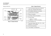
... 4. See "Changing Setup Options." D Setup is in progress. H Secondary Display: MAX, MIN, AVG, or offset. 51 & 52 Series II Users Manual Display Elements 23 4 1 10 9 Figure 2. B The displayed readings do not change. Model 52: T1, T2, or T1-T2 reading. I The thermocouple type. Display Elements A The thermocouple measurement includes an offset. E Low battery. F Primary Display. Model 52: T1or T2 reading. Replace the batteries. G The temperature unit. J Time Display: The elapsed time...
... 4. See "Changing Setup Options." D Setup is in progress. H Secondary Display: MAX, MIN, AVG, or offset. 51 & 52 Series II Users Manual Display Elements 23 4 1 10 9 Figure 2. B The displayed readings do not change. Model 52: T1, T2, or T1-T2 reading. I The thermocouple type. Display Elements A The thermocouple measurement includes an offset. E Low battery. F Primary Display. Model 52: T1or T2 reading. Replace the batteries. G The temperature unit. J Time Display: The elapsed time...
FE 51 & 52 II Users Manual
Page 11
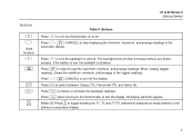
... off . 51 & 52 Series II Getting Started Buttons A G (Shift function) Q M C h T Table 5. Press G, M (CANCEL) to test the display. Press h to switch between Celsius (oC), Fahrenheit (oF), and Kelvin (K). The backlight turns off this display. Model 52: Press T to step through the maximum, minimum, and average readings. Press C to freeze or unfreeze the displayed readings. All display elements appear. If the battery is...
... off . 51 & 52 Series II Getting Started Buttons A G (Shift function) Q M C h T Table 5. Press G, M (CANCEL) to test the display. Press h to switch between Celsius (oC), Fahrenheit (oF), and Kelvin (K). The backlight turns off this display. Model 52: Press T to step through the maximum, minimum, and average readings. Press C to freeze or unfreeze the displayed readings. All display elements appear. If the battery is...
FE 51 & 52 II Users Manual
Page 12
Press N to scroll to the Setup option you want to enter a Setup option. 51 & 52 Series II Users Manual D K N E Table 5. Press E to change . Press N to increase the displayed setting. Press K to decrease the displayed setting. Press E again to change . Buttons (cont.) Press D to start or exit Setup. (See "Changing Setup Options.") Press K to scroll to the Setup option you want to store the displayed setting in memory. 8
Press N to scroll to the Setup option you want to enter a Setup option. 51 & 52 Series II Users Manual D K N E Table 5. Press E to change . Press N to increase the displayed setting. Press K to decrease the displayed setting. Press E again to change . Buttons (cont.) Press D to start or exit Setup. (See "Changing Setup Options.") Press K to scroll to the Setup option you want to store the displayed setting in memory. 8
FE 51 & 52 II Users Manual
Page 13
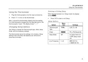
..., sleep mode, and line frequency settings. Plug the thermocouple(s) into the selected input or the thermocouple is in its memory. Using the Thermometer 1. Setup settings reset only when the batteries are removed for more than 2 minutes. 51 & 52 Series II Using the Thermometer Entering or Exiting Setup When the thermometer is "open," the display shows "- - - -" Changing Setup Options Use Setup to turn on ) or 0FF (sleep mode off) Line Frequency Li...
..., sleep mode, and line frequency settings. Plug the thermocouple(s) into the selected input or the thermocouple is in its memory. Using the Thermometer 1. Setup settings reset only when the batteries are removed for more than 2 minutes. 51 & 52 Series II Using the Thermometer Entering or Exiting Setup When the thermometer is "open," the display shows "- - - -" Changing Setup Options Use Setup to turn on ) or 0FF (sleep mode off) Line Frequency Li...
FE 51 & 52 II Users Manual
Page 14
... the setting you want to change the thermocouple type. Pressing any button wakes the thermometer and returns it is automatically disabled in MIN MAX mode. Press E to indicate that you want to use appears on the thermometer and is no button press occurs for 20 minutes. The offset automatically resets to its previous state. 51 & 52 Series II Users Manual Changing a Setup...
... the setting you want to change the thermocouple type. Pressing any button wakes the thermometer and returns it is automatically disabled in MIN MAX mode. Press E to indicate that you want to use appears on the thermometer and is no button press occurs for 20 minutes. The offset automatically resets to its previous state. 51 & 52 Series II Users Manual Changing a Setup...
FE 51 & 52 II Users Manual
Page 15
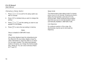
... Code is connected, the T2 reading appears in the primary display. T 3. Model 52: If only thermocouple T2 is : Type J K E T N Color Black Yellow Purple Blue Orange 1. The temperature reading appears in the primary display. 11 The display shows 0L (overload) when the temperature being measured is outside the thermocouple's valid range. Displaying Temperatures 1. Measuring Temperatures Connecting a Thermocouple To change the thermocouple type, see "Changing Setup...
... Code is connected, the T2 reading appears in the primary display. T 3. Model 52: If only thermocouple T2 is : Type J K E T N Color Black Yellow Purple Blue Orange 1. The temperature reading appears in the primary display. 11 The display shows 0L (overload) when the temperature being measured is outside the thermocouple's valid range. Displaying Temperatures 1. Measuring Temperatures Connecting a Thermocouple To change the thermocouple type, see "Changing Setup...
FE 51 & 52 II Users Manual
Page 16
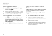
... freeze the readings on the display. 2. Press M to stabilize. 4. In Setup change the offset until the primary display reading matches the calibration temperature. (See "Changing Setup Options.") 12 Plug the thermocouple into the input connector. 2. 51 & 52 Series II Users Manual Holding the Displayed Readings 1. Press h to compensate for the errors of a specific thermocouple. The elapsed time since entering MIN MAX mode, or the time at which the minimum...
... freeze the readings on the display. 2. Press M to stabilize. 4. In Setup change the offset until the primary display reading matches the calibration temperature. (See "Changing Setup Options.") 12 Plug the thermocouple into the input connector. 2. 51 & 52 Series II Users Manual Holding the Displayed Readings 1. Press h to compensate for the errors of a specific thermocouple. The elapsed time since entering MIN MAX mode, or the time at which the minimum...
FE 51 & 52 II Users Manual
Page 17
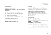
... its accuracy specifications, Fluke recommends that you or follow the calibration procedure in the service manual listed in Table 1 before replacing the batteries. 1. To calibrate the thermometer, contact Fluke for the Service Center nearest you calibrate the thermometer annually, starting one year after purchase. Loosen the screw and remove the battery door. 3. Turn off the thermometer if necessary. 2. Cleaning the Case and Holster Use soap and...
... its accuracy specifications, Fluke recommends that you or follow the calibration procedure in the service manual listed in Table 1 before replacing the batteries. 1. To calibrate the thermometer, contact Fluke for the Service Center nearest you calibrate the thermometer annually, starting one year after purchase. Loosen the screw and remove the battery door. 3. Turn off the thermometer if necessary. 2. Cleaning the Case and Holster Use soap and...
FE 51 & 52 II Users Manual
Page 18
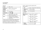
...connection to circuits in ) Battery Certification 3 AA batteries P, ) s Safety CSA C22.2 No. 1010.1 1992 EN 61010 Amendments 1, 2 CAT I OVERVOLTAGE (Installation) CATEGORY I, Pollution Degree 2 per IEC1010-1* * Refers to the level of Impulse Withstand Voltage protection provided. Example include protect electronic circuits. 80 PK-1 Thermocouple (supplied with thermometer) Type Temperature Range...+1832 oF) 0.1 oC / oF / K < 1000o 1.0 oC / oF / K ≥ 1000o 14 51 & 52 Series II Users Manual General Weight 280 g (10 oz) Dimensions (without holster) 2.8 cm × 7.8 cm × 16.2...
...connection to circuits in ) Battery Certification 3 AA batteries P, ) s Safety CSA C22.2 No. 1010.1 1992 EN 61010 Amendments 1, 2 CAT I OVERVOLTAGE (Installation) CATEGORY I, Pollution Degree 2 per IEC1010-1* * Refers to the level of Impulse Withstand Voltage protection provided. Example include protect electronic circuits. 80 PK-1 Thermocouple (supplied with thermometer) Type Temperature Range...+1832 oF) 0.1 oC / oF / K < 1000o 1.0 oC / oF / K ≥ 1000o 14 51 & 52 Series II Users Manual General Weight 280 g (10 oz) Dimensions (without holster) 2.8 cm × 7.8 cm × 16.2...
FE 51 & 52 II Users Manual
Page 19
...-t(y0p.5e:o±F[)0] .05 % of [below −100 oC (−148 oF): add 0.15 % of 1 year. The above specifications do not include thermocouple error. 51 & 52 Series II Replacement Parts and Accessories Replacement Parts and Accessories Accessory Part Number Holster and Flex Stand™ Assembly 1272438 AA NEDA 15A IEC LR6 batteries 376756 80PK-1 K-Type Bead Thermocouple 773135 CD-ROM 1276106 Service Manual 1276123 15
...-t(y0p.5e:o±F[)0] .05 % of [below −100 oC (−148 oF): add 0.15 % of 1 year. The above specifications do not include thermocouple error. 51 & 52 Series II Replacement Parts and Accessories Replacement Parts and Accessories Accessory Part Number Holster and Flex Stand™ Assembly 1272438 AA NEDA 15A IEC LR6 batteries 376756 80PK-1 K-Type Bead Thermocouple 773135 CD-ROM 1276106 Service Manual 1276123 15


