Technical Reference
Page 26
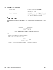
...signal Output signal: Output waveform: Voltage = Approximately 24V DC Current = 1 A or less Outputs the waveforms in Figure 1-8 to use the printer power supply (connector pin 4) for the drawer power source. 1-14 Features and General Specifications Rev.B CAUTION: To avoid an overcurrent, the resistance ...of the connector. t1 x 2 ms t2 x 2 ms Figure 1-9 Drawer kick-out drive signal output waveform NOTES: t Two driver transistors cannot be 24 Ω or more. t The drawer drive duty must be as shown below: ON time (ON time + OFF time) ≤...
...signal Output signal: Output waveform: Voltage = Approximately 24V DC Current = 1 A or less Outputs the waveforms in Figure 1-8 to use the printer power supply (connector pin 4) for the drawer power source. 1-14 Features and General Specifications Rev.B CAUTION: To avoid an overcurrent, the resistance ...of the connector. t1 x 2 ms t2 x 2 ms Figure 1-9 Drawer kick-out drive signal output waveform NOTES: t Two driver transistors cannot be 24 Ω or more. t The drawer drive duty must be as shown below: ON time (ON time + OFF time) ≤...
Technical Reference
Page 58
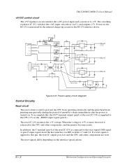
...and the CPU and other components, and the printer becomes ready. C 33 F . The reset IC (U9) monitors the +5V voltage. If a reset signal is applied to this , the OUT terminal output (pin5) of the reset IC (U9) is connected to +5V. TM-U200D/U200PD Technical Manual +5V DC control circuit The...addition, the C terminal (pin 4) of unstable voltage immediately after the power is generated by the internal charge-up circuit on the RS-232 interface driver. The switching regulator IC (U1) switches the +24V input, smooths it to the reset signal (DSR signal or pin 25 input signal) from ...
...and the CPU and other components, and the printer becomes ready. C 33 F . The reset IC (U9) monitors the +5V voltage. If a reset signal is applied to this , the OUT terminal output (pin5) of the reset IC (U9) is connected to +5V. TM-U200D/U200PD Technical Manual +5V DC control circuit The...addition, the C terminal (pin 4) of unstable voltage immediately after the power is generated by the internal charge-up circuit on the RS-232 interface driver. The switching regulator IC (U1) switches the +24V input, smooths it to the reset signal (DSR signal or pin 25 input signal) from ...
Technical Reference
Page 153
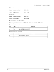
Printer reception data level RD1 RD2 Read data H L Receiving data line is low level L H Receiving data line is high level Printer transmission data level SD1 SD2 H L L H Sending data line is low level Sending data line is connected to the RS-485 driver. TM-U200D/U200PD Technical Manual "H" indicates: SD1 < SD2 RD1 < RD2 "L" indicates: SD1 > SD2 RD1 > RD2 The transmission data is H = 1, L = 0 Note: This format is used when the UART for RS-232 is high level Send data Rev. B Appendix A-5
Printer reception data level RD1 RD2 Read data H L Receiving data line is low level L H Receiving data line is high level Printer transmission data level SD1 SD2 H L L H Sending data line is low level Sending data line is connected to the RS-485 driver. TM-U200D/U200PD Technical Manual "H" indicates: SD1 < SD2 RD1 < RD2 "L" indicates: SD1 > SD2 RD1 > RD2 The transmission data is H = 1, L = 0 Note: This format is used when the UART for RS-232 is high level Send data Rev. B Appendix A-5


