User Manual
Page 3
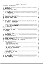
...steps 17 1.2 Repacking steps 17 2. Power Connection 16 INSTALLATION OF MX-82 F/T 17 1. Cartridge Ribbon Setting 22 5. Power Connection 34 Introduction 1 2. Counting the Parts 18 3. Mounting and Dismounting of the Printer 19 4. Unpacking 3 1.1 Unpacking steps 3 1.2 Repacking steps 3 2. Cartridge Ribbon Setting 8 5. Gap Adjustment 34 9. TABLE OF CONTENTS GENERAL DESCRIPTION 1 1. Installation of Tractor Unit 24 7. Paper Loading 25 7.1 Fanfold paper 25 7.1.1 Loading of fanfold paper 25 7.1.2 Removal of fanfold paper 27 7.1.3 Column layout on fanfold...
...steps 17 1.2 Repacking steps 17 2. Power Connection 16 INSTALLATION OF MX-82 F/T 17 1. Cartridge Ribbon Setting 22 5. Power Connection 34 Introduction 1 2. Counting the Parts 18 3. Mounting and Dismounting of the Printer 19 4. Unpacking 3 1.1 Unpacking steps 3 1.2 Repacking steps 3 2. Cartridge Ribbon Setting 8 5. Gap Adjustment 34 9. TABLE OF CONTENTS GENERAL DESCRIPTION 1 1. Installation of Tractor Unit 24 7. Paper Loading 25 7.1 Fanfold paper 25 7.1.1 Loading of fanfold paper 25 7.1.2 Removal of fanfold paper 27 7.1.3 Column layout on fanfold...
User Manual
Page 4
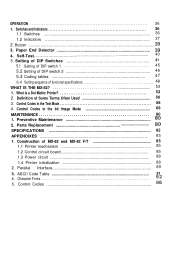
... Maintenance i3 2. Control Codes Parallel Interface 89 3. ASCII Code Table 91 4. Parts Replacement SPECIFICATIONS 82 APPENDIXES ...85 1. Construction of funcional specifications 48 WHAT IS THE MX-82 53 1. Paper End Detector 4. Control Codes in the bit Image Mode 69 MAINTENANCE 80 1. Character Fonts 96' 5. Setting of DIP Switches 41 5.1 Setting of DIP switch 1 45 5.2 Setting of DIP switch 2 46 5.3 Coding tables 47 6.4 Setting sequence of MX-82 and MX-82 F/T 85 1.1 Printer mechanism 85 1.2 Control circuit board 85 1.3 Power circuit 88 1.4 Printer initialization...
... Maintenance i3 2. Control Codes Parallel Interface 89 3. ASCII Code Table 91 4. Parts Replacement SPECIFICATIONS 82 APPENDIXES ...85 1. Construction of funcional specifications 48 WHAT IS THE MX-82 53 1. Paper End Detector 4. Control Codes in the bit Image Mode 69 MAINTENANCE 80 1. Character Fonts 96' 5. Setting of DIP Switches 41 5.1 Setting of DIP switch 1 45 5.2 Setting of DIP switch 2 46 5.3 Coding tables 47 6.4 Setting sequence of MX-82 and MX-82 F/T 85 1.1 Printer mechanism 85 1.2 Control circuit board 85 1.3 Power circuit 88 1.4 Printer initialization...
User Manual
Page 5
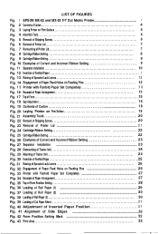
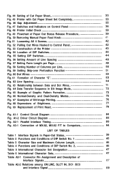
LIST OF FIGURES Fig. 1 EPSON MX-82 and MX-82 F/T Dot Matrix Printer 1 Fig. 2 Contents of Carton 4 Fig. 3 Laying Printer on Firm Surface 5 Fig. 4 Assembly Tools 6 Fig. 5 Removal of Shipping Screws 6 Fig. 6 Removal of Printer Lid 7 Fig. 7 Remounting of Printer Lid 7 Fig. 8 Cartridge Ribbon Setting 8 Fig. 9 Cartridge Ribbon Setting 9 Fig. 10 Examples of Correct and Incorrect Ribbon Setting 9 Fig. 11 Separator Installation 10 Fig. 12 Insertion of Fanfold Paper 11...
LIST OF FIGURES Fig. 1 EPSON MX-82 and MX-82 F/T Dot Matrix Printer 1 Fig. 2 Contents of Carton 4 Fig. 3 Laying Printer on Firm Surface 5 Fig. 4 Assembly Tools 6 Fig. 5 Removal of Shipping Screws 6 Fig. 6 Removal of Printer Lid 7 Fig. 7 Remounting of Printer Lid 7 Fig. 8 Cartridge Ribbon Setting 8 Fig. 9 Cartridge Ribbon Setting 9 Fig. 10 Examples of Correct and Incorrect Ribbon Setting 9 Fig. 11 Separator Installation 10 Fig. 12 Insertion of Fanfold Paper 11...
User Manual
Page 6
... Paper Sheet Set Completely 33 Fig. 46 Gap Adjustment 35 Fig. 47 Switches and Indicators on Control Panel 36 Fig. 48 Printer Initial Check 38 Fig. 49 Flowchart of Paper Out Status Release Procedure 39 Fig. 50 Removing Manual Paper Feed Knob 41 Fig. 51 Loosening All 4 Screws 42 Fig. 52 Pulling Out Wires Hooked to Computers 94 LIST OF TABLES Table 1 Interface Signals in Bit Image Mode...
... Paper Sheet Set Completely 33 Fig. 46 Gap Adjustment 35 Fig. 47 Switches and Indicators on Control Panel 36 Fig. 48 Printer Initial Check 38 Fig. 49 Flowchart of Paper Out Status Release Procedure 39 Fig. 50 Removing Manual Paper Feed Knob 41 Fig. 51 Loosening All 4 Screws 42 Fig. 52 Pulling Out Wires Hooked to Computers 94 LIST OF TABLES Table 1 Interface Signals in Bit Image Mode...
User Manual
Page 7
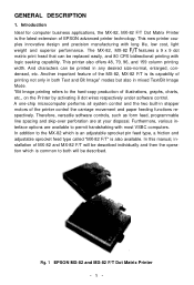
...-chip microcomputer performs all system control and the two built-in any desired size-normal, enlarged, condensed, etc. Furthermore, various interface options are at your disposal. In this manual, installation of MX-82 and MX-82 F/T will be replaced easily, and 80 CPS bidirectional printing with long life, low cost, light weight and superior performance. This new printer couples innovative design and precision manufacturing...
...-chip microcomputer performs all system control and the two built-in any desired size-normal, enlarged, condensed, etc. Furthermore, various interface options are at your disposal. In this manual, installation of MX-82 and MX-82 F/T will be replaced easily, and 80 CPS bidirectional printing with long life, low cost, light weight and superior performance. This new printer couples innovative design and precision manufacturing...
User Manual
Page 8
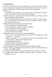
... by DIP switch setting or variable under software control. (3) Wide variation of CRT screen could be printed out onto the paper. (2) Both text printing for general data processing and Bit Image printing for hobbies. In the Bit Image printing, both normal density (576 dots/line in horizontal direction) and dual density (1152 dots/line in propotion to that of printing widths and character sizes. (a) 48 characters/line (enlarged...
... by DIP switch setting or variable under software control. (3) Wide variation of CRT screen could be printed out onto the paper. (2) Both text printing for general data processing and Bit Image printing for hobbies. In the Bit Image printing, both normal density (576 dots/line in horizontal direction) and dual density (1152 dots/line in propotion to that of printing widths and character sizes. (a) 48 characters/line (enlarged...
User Manual
Page 11
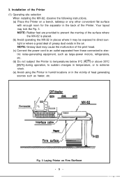
... dust may cause the malfunction of the print head. (c) Connect the power cord to an outlet separated from those connected to electric noise-generating equipment, such as heater, etc. ,i , CRT displav iFloppy disk unit MX-82 / I 2i!!J Interface cable / I Paper / III II Firm surface / - Installation of the Printer (1) Operating site selection When installing the MX-82, observe the following instructions. (a) Place the Printer on Firm Surface -5- Fig. 3 Laying...
... dust may cause the malfunction of the print head. (c) Connect the power cord to an outlet separated from those connected to electric noise-generating equipment, such as heater, etc. ,i , CRT displav iFloppy disk unit MX-82 / I 2i!!J Interface cable / I Paper / III II Firm surface / - Installation of the Printer (1) Operating site selection When installing the MX-82, observe the following instructions. (a) Place the Printer on Firm Surface -5- Fig. 3 Laying...
User Manual
Page 16
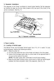
... paper The MX-82 Printer accommodates fanfold paper from the platen. 3. STEP 1. Loading of the printer mechanism. (See Fig. 11) Paper Fig. 11 Separator installation 6. If not, set it from 4" to 10" in width. NOTE: The paper guide roller contributes to smooth paper feeding. Raise the two paper holding covers, and be sure to insert the fanfold paper between the frame and plastic roller of the Printer contributes to smooth paper feeding. 4. Turn...
... paper The MX-82 Printer accommodates fanfold paper from the platen. 3. STEP 1. Loading of the printer mechanism. (See Fig. 11) Paper Fig. 11 Separator installation 6. If not, set it from 4" to 10" in width. NOTE: The paper guide roller contributes to smooth paper feeding. Raise the two paper holding covers, and be sure to insert the fanfold paper between the frame and plastic roller of the Printer contributes to smooth paper feeding. 4. Turn...
User Manual
Page 20
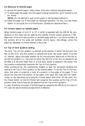
... the fanfold paper. Alignment of the print start position on . 6.2 Removal of fanfold paper To remove the fanfold paper, follow either of the two methods described below. (1) To disengage the paper from the Top of Form position. Now, the printing can be used as the indexes of print column positions (1-96). In case of feeding one page of fanfold paper by operating the MX-82 by adjusting it...
... the fanfold paper. Alignment of the print start position on . 6.2 Removal of fanfold paper To remove the fanfold paper, follow either of the two methods described below. (1) To disengage the paper from the Top of Form position. Now, the printing can be used as the indexes of print column positions (1-96). In case of feeding one page of fanfold paper by operating the MX-82 by adjusting it...
User Manual
Page 22
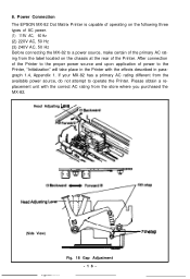
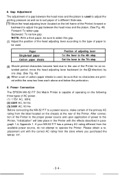
After connection of the Printer to operate the Printer. Head Adjusting Leve (Side View) \@ F--- -w ) 7th step Fig. 18 Gap Adjustment -16- Please obtain a replacement unit with the effects described in paragraph 1.4, Appendix 1. Power Connection The EPSON MX-82 Dot Matrix Printer is capable of operating on the following three types of AC power. (1) 115V AC, 60 Hz (2) 220V AC, 50 Hz (3) 240V AC, 50 Hz Before connecting the MX-82 to a power source, make certain...
After connection of the Printer to operate the Printer. Head Adjusting Leve (Side View) \@ F--- -w ) 7th step Fig. 18 Gap Adjustment -16- Please obtain a replacement unit with the effects described in paragraph 1.4, Appendix 1. Power Connection The EPSON MX-82 Dot Matrix Printer is capable of operating on the following three types of AC power. (1) 115V AC, 60 Hz (2) 220V AC, 50 Hz (3) 240V AC, 50 Hz Before connecting the MX-82 to a power source, make certain...
User Manual
Page 36
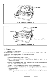
... the paper guide roller is at the center of the shaft. Pull the scale toward the front of the Printer to smooth paper feeding. 5. STEP 1. Insert the cut paper sheet can be installed without removing the separa- r Fig. 37 Loading of Roll Paper (2) Release Lever Manual Paper Feed Knob Fig. 38 Loading of Roll Paper (3) 7.3 Cut paper sheet 7.3.1 Loading of cut paper sheet The MX-82 F/T accommodates cut paper sheet, observe the following procedure. To load a cut paper sheets...
... the paper guide roller is at the center of the shaft. Pull the scale toward the front of the Printer to smooth paper feeding. 5. STEP 1. Insert the cut paper sheet can be installed without removing the separa- r Fig. 37 Loading of Roll Paper (2) Release Lever Manual Paper Feed Knob Fig. 38 Loading of Roll Paper (3) 7.3 Cut paper sheet 7.3.1 Loading of cut paper sheet The MX-82 F/T accommodates cut paper sheet, observe the following procedure. To load a cut paper sheets...
User Manual
Page 40
... printed within the area two lines each above and below the perforation. 8. Paper Single-leaf paper Carbon paper sheets Position of adjusting lever Set the lever to a power source, make certain of the primary AC rating from the store where you purchased the MX-82 F/T. -34- Power Connection The EPSON MX-82 F/T Dot Matrix Printer is used . Backward: To narrow gap. Please obtain a replacement unit with the effects described in the 0 direction...
... printed within the area two lines each above and below the perforation. 8. Paper Single-leaf paper Carbon paper sheets Position of adjusting lever Set the lever to a power source, make certain of the primary AC rating from the store where you purchased the MX-82 F/T. -34- Power Connection The EPSON MX-82 F/T Dot Matrix Printer is used . Backward: To narrow gap. Please obtain a replacement unit with the effects described in the 0 direction...
User Manual
Page 42
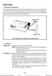
... set the Printer in the OFFLINE mode, The switch does not function while the Printer is exhausted or if a mechanical error occurs in printing. Depressing the ON-LINE switch will set in the printer. The Printer is automatically placed OFF-LINE if the paper supply is actively engaged in the Printer. NOTE: Before turning this section, panel operating procedures are covered in conjunction with the Printer. (See Fig. 47 for the control panel.) I Control Panel...
... set the Printer in the OFFLINE mode, The switch does not function while the Printer is exhausted or if a mechanical error occurs in printing. Depressing the ON-LINE switch will set in the printer. The Printer is automatically placed OFF-LINE if the paper supply is actively engaged in the Printer. NOTE: Before turning this section, panel operating procedures are covered in conjunction with the Printer. (See Fig. 47 for the control panel.) I Control Panel...
User Manual
Page 47
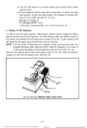
... auto-line feed. NOTE: Turn the power off whenever you attempt to be printed. To gain access to pin No. 33. 5. equately discharge static electricity which might be removed. The DIP switches (SW1 and SW2) located on the control circuit board of the Printer must be charged in Fig. 54. Ad- c) Set the adequate ASCII code data to open up the printer case. Remove the manual paper feed knob (black knob on the control...
... auto-line feed. NOTE: Turn the power off whenever you attempt to be printed. To gain access to pin No. 33. 5. equately discharge static electricity which might be removed. The DIP switches (SW1 and SW2) located on the control circuit board of the Printer must be charged in Fig. 54. Ad- c) Set the adequate ASCII code data to open up the printer case. Remove the manual paper feed knob (black knob on the control...

User Manual
Page 58
... printer? 2. Definitions of printers are ; 1. Broadly speaking, the EPSON MX-82 belongs to the following categories. * Impact printer * Dot matrix printer * Serial printer with the text mode because an ordinary printer has it cannot print data at almost the same time. This chapter describes the MX-82, MX-82 F/T (hereinafter refered to as "Bit Image". 1. As you want. The receive only printer means that it . But if the printer has buffer memory...
... printer? 2. Definitions of printers are ; 1. Broadly speaking, the EPSON MX-82 belongs to the following categories. * Impact printer * Dot matrix printer * Serial printer with the text mode because an ordinary printer has it cannot print data at almost the same time. This chapter describes the MX-82, MX-82 F/T (hereinafter refered to as "Bit Image". 1. As you want. The receive only printer means that it . But if the printer has buffer memory...
User Manual
Page 64
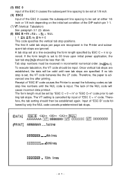
NOTES: 1. When power is applied, the amount of line spacing is set , one line after printing. (4) FF (Form Feed) The FF code causes the Printer to execute the printing of all data preceding this code will cause incorrect data printout. -58- tion where the print head stops. The first 12 tab stops per page is not set at that time. The excess tab positions, if specified, will not be ignored...
NOTES: 1. When power is applied, the amount of line spacing is set , one line after printing. (4) FF (Form Feed) The FF code causes the Printer to execute the printing of all data preceding this code will cause incorrect data printout. -58- tion where the print head stops. The first 12 tab stops per page is not set at that time. The excess tab positions, if specified, will not be ignored...
User Manual
Page 67
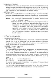
... Printer to 66 lines upon initial power application, the last tab stop line numbers until new tab stops are recognized in incremental numerical order. (nk 5 nk+t). Input of "ESC B" code followed by input of "ESC C + n" code. A tab stop positions. Therefore, the tab setting should be less than 66. DATA] PRINT] AAAAAiiA .,... 1st line BBBbbBir . . . . . 4th lines CCCCCCC . . . . 6th lines DDDDDDD . 10th lines -61- If no tab stop is set at a line...
... Printer to 66 lines upon initial power application, the last tab stop line numbers until new tab stops are recognized in incremental numerical order. (nk 5 nk+t). Input of "ESC B" code followed by input of "ESC C + n" code. A tab stop positions. Therefore, the tab setting should be less than 66. DATA] PRINT] AAAAAiiA .,... 1st line BBBbbBir . . . . . 4th lines CCCCCCC . . . . 6th lines DDDDDDD . 10th lines -61- If no tab stop is set at a line...
User Manual
Page 71
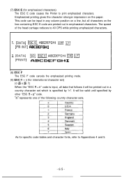
... for specific code tables and character fonts, refer to print emphasized characters. "n" represents one of the head carriage reduces to 40 CPS while printing emphasized characters. 1. [DATAI -E] ABCDEFGHI ICR] ILF] LPR INTI CIBCDEFGHI 2. [DATA] [PRINT] m (ESCE] ABCDEFGHI m m ABCDEFGH I (8) ESC F The ESC F code cancels the emphasized printing mode. (9) ESC R + n (for international character set which is input, all characters on the paper. This code can...
... for specific code tables and character fonts, refer to print emphasized characters. "n" represents one of the head carriage reduces to 40 CPS while printing emphasized characters. 1. [DATAI -E] ABCDEFGHI ICR] ILF] LPR INTI CIBCDEFGHI 2. [DATA] [PRINT] m (ESCE] ABCDEFGHI m m ABCDEFGH I (8) ESC F The ESC F code cancels the emphasized printing mode. (9) ESC R + n (for international character set which is input, all characters on the paper. This code can...
User Manual
Page 73
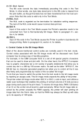
... BS code is cleared from the print buffer, as the latter "APPLE II", the MX-82 has no graphic characters but allow you to be discussed next. To do that data has not been transferred from Text to perform dual-density bit image printing. The printer enters bit image mode when ESC K or ESC L code is used in the Text Mode causes the Printer's operation mode to control all...
... BS code is cleared from the print buffer, as the latter "APPLE II", the MX-82 has no graphic characters but allow you to be discussed next. To do that data has not been transferred from Text to perform dual-density bit image printing. The printer enters bit image mode when ESC K or ESC L code is used in the Text Mode causes the Printer's operation mode to control all...
User Manual
Page 93
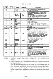
... time of this signal is set "LOW" for this signal being at signal ground level. As to the wiring for each other. To prevent noise effectively, these cables should be sure to use a twisted-pair cable for the interface, be shielded and connected to the printer is possible only when the level of shipment is "LOW". (Internal fixing can be connected at "LOW" level, the paper...
... time of this signal is set "LOW" for this signal being at signal ground level. As to the wiring for each other. To prevent noise effectively, these cables should be sure to use a twisted-pair cable for the interface, be shielded and connected to the printer is possible only when the level of shipment is "LOW". (Internal fixing can be connected at "LOW" level, the paper...


