
User Manual
Page 2
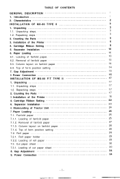
...of cut paper sheet 30 8. Unpacking steps 17 1.2. Dismounting of roll paper 29 7.3. Fanfold paper 25 7.1.1. Loading of Tractor Unit 24 7. Power Connection 34 -i- Introduction 1 2. Top of the Printer 5 4. Unpacking steps 3 1.2. Counting the Parts 3 3. Cartridge Ribbon Setting 22 6. Cut paper sheet 30 7.3.1. Installation of form position setting 14 7. Paper Loading 25 7.1. Repacking steps 3 2. Cartridge Ribbon Setting 8 5. Removal of fanfold paper 27 7.1.3. Column layout on fanfold paper 14 6.4. Power Connection 15 INSTALLATION OF MX-80 F/T TYPE II...
...of cut paper sheet 30 8. Unpacking steps 17 1.2. Dismounting of roll paper 29 7.3. Fanfold paper 25 7.1.1. Loading of Tractor Unit 24 7. Power Connection 34 -i- Introduction 1 2. Top of the Printer 5 4. Unpacking steps 3 1.2. Counting the Parts 3 3. Cartridge Ribbon Setting 22 6. Cut paper sheet 30 7.3.1. Installation of form position setting 14 7. Paper Loading 25 7.1. Repacking steps 3 2. Cartridge Ribbon Setting 8 5. Removal of fanfold paper 27 7.1.3. Column layout on fanfold paper 14 6.4. Power Connection 15 INSTALLATION OF MX-80 F/T TYPE II...
User Manual
Page 3
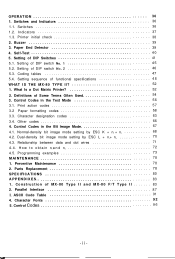
... 3. Setting of MX-80 Type II and MX-80 F/T Type II 83 2. Print action codes 57 3.2 Paper formatting codes 58 3.3. Normal-density bit image mode setting by ESC L + nl + n2 70 4.3. Parts Replacement 78 SPECIFICATIONS 80 APPENDIXES 83 1. Parallel Interface 87 3. Control Codes 9 6 -ii- Switches and Indicators 36 1.1. Printer initial check 38 2. Paper End Detector 39 4. Coding tables 47 5.4. Definitions of DIP switch No. 1 4 5 5.2. Other codes 66 4. Control Codes in the Bit Image Mode 67 4.1. Dual-density bit image mode setting...
... 3. Setting of MX-80 Type II and MX-80 F/T Type II 83 2. Print action codes 57 3.2 Paper formatting codes 58 3.3. Normal-density bit image mode setting by ESC L + nl + n2 70 4.3. Parts Replacement 78 SPECIFICATIONS 80 APPENDIXES 83 1. Parallel Interface 87 3. Control Codes 9 6 -ii- Switches and Indicators 36 1.1. Printer initial check 38 2. Paper End Detector 39 4. Coding tables 47 5.4. Definitions of DIP switch No. 1 4 5 5.2. Other codes 66 4. Control Codes in the Bit Image Mode 67 4.1. Dual-density bit image mode setting...
User Manual
Page 4
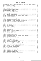
LIST OF FIGURES Fig. 1 EPSON MX-80 Type II and MX-80 F/T Type II Dot Matrix Printers ... 1 Fig. 2 Contents of Carton 4 Fig. 3 Laying Printer on Firm Surface 5 Fig. 4 Assembly Tools 6 Fig. 5 Removal of Shipping Screws 7 Fig. 6 Removal of Printer Lid 7 Fig. 7 Remounting of Printer Lid 8 Fig. 8 Cartridge Ribbon Setting 8 Fig. 9 Cartridge Ribbon Setting 9 Fig. 10 Examples of Correct and Incorrect Ribbon Setting 9 Fig. 11 Separator Installation 10 Fig. 12...
LIST OF FIGURES Fig. 1 EPSON MX-80 Type II and MX-80 F/T Type II Dot Matrix Printers ... 1 Fig. 2 Contents of Carton 4 Fig. 3 Laying Printer on Firm Surface 5 Fig. 4 Assembly Tools 6 Fig. 5 Removal of Shipping Screws 7 Fig. 6 Removal of Printer Lid 7 Fig. 7 Remounting of Printer Lid 8 Fig. 8 Cartridge Ribbon Setting 8 Fig. 9 Cartridge Ribbon Setting 9 Fig. 10 Examples of Correct and Incorrect Ribbon Setting 9 Fig. 11 Separator Installation 10 Fig. 12...
User Manual
Page 5
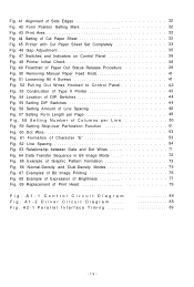
Fig. 41 Alignment of Side Edges 32 Fig. 42 Form Position Setting Mark 32 Fig. 43 Print Area 3 2 Fig. 44 Setting of Cut Paper Sheet 33 Fig. 45 Printer with Cut Paper Sheet Set Completely 33 Fig. 46 Gap Adjustment 35 Fig. 47 Switches and Indicators on Control Panel 36 Fig. 48 Printer Initial Check 38 Fig. 49 Flowchart of Paper Out Status Release Procedure 39 Fig. 50 Removing Manual Paper Feed Knob 41...
Fig. 41 Alignment of Side Edges 32 Fig. 42 Form Position Setting Mark 32 Fig. 43 Print Area 3 2 Fig. 44 Setting of Cut Paper Sheet 33 Fig. 45 Printer with Cut Paper Sheet Set Completely 33 Fig. 46 Gap Adjustment 35 Fig. 47 Switches and Indicators on Control Panel 36 Fig. 48 Printer Initial Check 38 Fig. 49 Flowchart of Paper Out Status Release Procedure 39 Fig. 50 Removing Manual Paper Feed Knob 41...
User Manual
Page 7
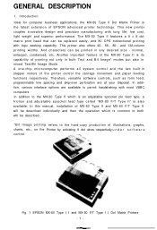
... Bit Image* modes but also in mixed Text/Bit Image Mode. Fig. 1 EPSON MX-80 Type I I and MX-80 F/T Type I I Dot Matrix Printers -1- A one-chip microcomputer performs all system control and the two built-in any desired size - The MX-80 Type II features a 9 x 9 dot matrix print head that can be replaced easily, and 80 CPS bidirectional printing with logic seeking capability. Therefore, versatile software controls, such as form feed, programmable line...
... Bit Image* modes but also in mixed Text/Bit Image Mode. Fig. 1 EPSON MX-80 Type I I and MX-80 F/T Type I I Dot Matrix Printers -1- A one-chip microcomputer performs all system control and the two built-in any desired size - The MX-80 Type II features a 9 x 9 dot matrix print head that can be replaced easily, and 80 CPS bidirectional printing with logic seeking capability. Therefore, versatile software controls, such as form feed, programmable line...
User Manual
Page 8
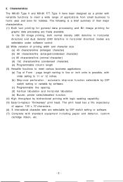
... MX-80 Type II and MX-80 F/T Type II have been designed as a printer with logic seeking capability. (5) Easy-to home uses and even for graphic data processing are selectable by bidirectional printing with versatile functions to 11 or 12 inches. (b) Skip-over perforation - page length setting in horizontal direction) modes are selectable under software control. (2) Wide variation of printing width and character size (a) 40 characters/line...
... MX-80 Type II and MX-80 F/T Type II have been designed as a printer with logic seeking capability. (5) Easy-to home uses and even for graphic data processing are selectable by bidirectional printing with versatile functions to 11 or 12 inches. (b) Skip-over perforation - page length setting in horizontal direction) modes are selectable under software control. (2) Wide variation of printing width and character size (a) 40 characters/line...
User Manual
Page 11
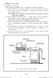
... of the print head. (c) Connect the power cord to an outlet separated from those connected to electric noise-generating equipment, such as heater, etc. CRT Display Fig. 3 Laying Printer on a bench, tabletop or any other convenient flat surface with enough room for the separator in the back of the Printer. NOTE: Rubber feet are provided to direct sunlight or...
... of the print head. (c) Connect the power cord to an outlet separated from those connected to electric noise-generating equipment, such as heater, etc. CRT Display Fig. 3 Laying Printer on a bench, tabletop or any other convenient flat surface with enough room for the separator in the back of the Printer. NOTE: Rubber feet are provided to direct sunlight or...
User Manual
Page 20
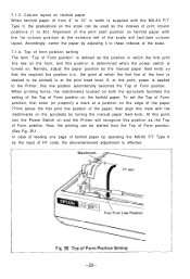
... case of feeding one page of fanfold paper by operating the MX-80 Type II by adjusting it to 10" in which the first line of the form is supplied with the MX-80 Type I I, the graduations on the sprockets by turning the manual paper feed knob. 6.3. If, at the print head level. At this line position automatically becomes the Top of Form position. Alignment of the print start position...
... case of feeding one page of fanfold paper by operating the MX-80 Type II by adjusting it to 10" in which the first line of the form is supplied with the MX-80 Type I I, the graduations on the sprockets by turning the manual paper feed knob. 6.3. If, at the print head level. At this line position automatically becomes the Top of Form position. Alignment of the print start position...
User Manual
Page 21
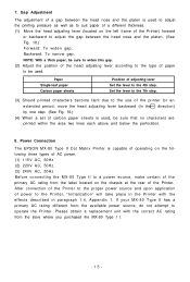
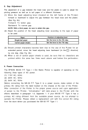
... obtain a replacement unit with the effects described in the direction) by one step. (See Fig. 18.) (4) When a set of the primary AC rating from the store where you purchased the MX-80 Type I I. -15- Power Connection The EPSON MX-80 Type II Dot Matrix Printer is used to adjust the printing pressure as well as to suit paper of a different thickness. (1) Move the head adjusting lever (located on the...
... obtain a replacement unit with the effects described in the direction) by one step. (See Fig. 18.) (4) When a set of the primary AC rating from the store where you purchased the MX-80 Type I I. -15- Power Connection The EPSON MX-80 Type II Dot Matrix Printer is used to adjust the printing pressure as well as to suit paper of a different thickness. (1) Move the head adjusting lever (located on the...
User Manual
Page 34
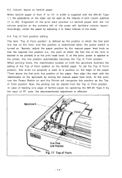
... is determined when the power switch is effective. Namely, adjust the paper position by adjusting it to 80). At this point, turn the Power Switch on . Accordingly, center the paper by the manual paper feed knob S O that the required line position (i.e., the point at the extreme left of fanfold paper by operating the MX-80 F/T Type II by turning the manual paper feed knob. Top of form position setting The term "Top...
... is determined when the power switch is effective. Namely, adjust the paper position by adjusting it to 80). At this point, turn the Power Switch on . Accordingly, center the paper by the manual paper feed knob S O that the required line position (i.e., the point at the extreme left of fanfold paper by operating the MX-80 F/T Type II by turning the manual paper feed knob. Top of form position setting The term "Top...
User Manual
Page 40
... gap. Please obtain a replacement unit with the correct AC rating from the available power source, do not attempt to adjust the gap between the head nose and the platen is used, be used to adjust the printing pressure as well as to the Printer, "Initialization" will take place in the Printer with the effects described in paragraph 1.4, Appendix 1. Power Connection The EPSON MX-80 F/T Type I I . -34...
... gap. Please obtain a replacement unit with the correct AC rating from the available power source, do not attempt to adjust the gap between the head nose and the platen is used, be used to adjust the printing pressure as well as to the Printer, "Initialization" will take place in the Printer with the effects described in paragraph 1.4, Appendix 1. Power Connection The EPSON MX-80 F/T Type I I . -34...
User Manual
Page 42
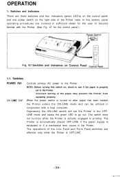
... the control panel and one power switch on , check to become familiar with a host computer. NOTE: Before turning this section, panel operating procedures are effective only while the Printer is turned on after paper has been loaded, the Printer enters the ON-LINE mode and can be utilized in the OFFLINE mode and cause the green LED to the Printer. Incorrect setting of the Line Feed and Form Feed switches are covered in the Printer...
... the control panel and one power switch on , check to become familiar with a host computer. NOTE: Before turning this section, panel operating procedures are effective only while the Printer is turned on after paper has been loaded, the Printer enters the ON-LINE mode and can be utilized in the OFFLINE mode and cause the green LED to the Printer. Incorrect setting of the Line Feed and Form Feed switches are covered in the Printer...
User Manual
Page 46
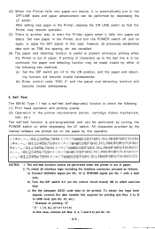
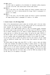
...: 1. Set new paper in the Printer, and turn the POWER switch off and on while depressing the LF switch. To obtain low logic level signals, connect the data transfer line required for printing (pin Nos. 2 to 9) to GND level (pin No. 33, etc.) * Example of printing "Z" " Z " = [ 5 , A ]H ( 0 1 0 1 1 0 1 0 ) In this operation. After setting new paper in the OFF-LINE state and paper advancement can be performed by this case, connect pin Nos. 2, 4, 7 and 9 to effect auto-line feed. The...
...: 1. Set new paper in the Printer, and turn the POWER switch off and on while depressing the LF switch. To obtain low logic level signals, connect the data transfer line required for printing (pin Nos. 2 to 9) to GND level (pin No. 33, etc.) * Example of printing "Z" " Z " = [ 5 , A ]H ( 0 1 0 1 1 0 1 0 ) In this operation. After setting new paper in the OFF-LINE state and paper advancement can be performed by this case, connect pin Nos. 2, 4, 7 and 9 to effect auto-line feed. The...

User Manual
Page 58
... image mode allows you know, many kinds of the needles called "dot wires" freely and programmably. Control codes in the text mode 4. The serial printer means that it does not have a keyboard. -52- This chapter describes the MX-80 Type II from the viewpoint of some special symbols. Definitions of hardware and software. In this mode a printer prints alphabets, numbers and some terms often used...
... image mode allows you know, many kinds of the needles called "dot wires" freely and programmably. Control codes in the text mode 4. The serial printer means that it does not have a keyboard. -52- This chapter describes the MX-80 Type II from the viewpoint of some special symbols. Definitions of hardware and software. In this mode a printer prints alphabets, numbers and some terms often used...
User Manual
Page 67
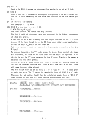
... stops per page are specified. Tab stop (nk)D should be less than 66. If no tab stop is set to 66 lines upon initial power application, the last tab stop numbers must be valid until the NUL code is advanced one line after printing. The form length must be received in the Printer; Input of "ESC B" code followed by input of "ESC C + n" code. Therefore, the paper...
... stops per page are specified. Tab stop (nk)D should be less than 66. If no tab stop is set to 66 lines upon initial power application, the last tab stop numbers must be valid until the NUL code is advanced one line after printing. The form length must be received in the Printer; Input of "ESC B" code followed by input of "ESC C + n" code. Therefore, the paper...
User Manual
Page 68
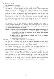
... N + n code or the DIP switch pin 2-4 on the control circuit board is OFF, skip-over perforation for setting skip-over perforation) The ESC N + n code is used to set the skip-over perforation function, which is determined by the number of lines where the value of "ESC C" code cancels the VT set by "ESC B" and the skip-over perforation is changed on the control...
... N + n code or the DIP switch pin 2-4 on the control circuit board is OFF, skip-over perforation for setting skip-over perforation) The ESC N + n code is used to set the skip-over perforation function, which is determined by the number of lines where the value of "ESC C" code cancels the VT set by "ESC B" and the skip-over perforation is changed on the control...
User Manual
Page 71
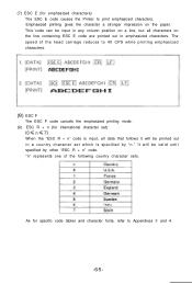
... head carriage reduces to 40 CPS while printing emphasized characters. (8) ESC F The ESC F code cancels the emphasized printing mode. (9) ESC R + n (for specific code tables and character fonts, refer to print emphasized characters. As for international character set which is input, all data that follows it will be printed out in emphasized characters. This code can be input in any column position on a line...
... head carriage reduces to 40 CPS while printing emphasized characters. (8) ESC F The ESC F code cancels the emphasized printing mode. (9) ESC R + n (for specific code tables and character fonts, refer to print emphasized characters. As for international character set which is input, all data that follows it will be printed out in emphasized characters. This code can be input in any column position on a line...
User Manual
Page 73
...," the MX-80 Type II has no graphic characters but allow you to perform dual-density bit image printing. The lack of the NUL code would cause incorrect data printout. (8) ESC K Input of this code in the Text Mode causes the Printer to control any dot in the CBM computer there is used in the Text Mode causes the Printer's operation mode to be used to...
...," the MX-80 Type II has no graphic characters but allow you to perform dual-density bit image printing. The lack of the NUL code would cause incorrect data printout. (8) ESC K Input of this code in the Text Mode causes the Printer to control any dot in the CBM computer there is used in the Text Mode causes the Printer's operation mode to be used to...
User Manual
Page 92
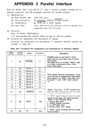
... are compatible with the TTL level. (2) Connector Plug: 57-30360 (AMPHENOL) It is out of paper. -87- Approx. 5µs pulse. During data entry 2. During printing operation 3. Connector pin assignment and descriptions of Interface Signals Description STROBE pulse to read data in the following cases: 1. The signal level is ready to 8th bits of signals. During printer error status. "LOW" indicates that data has...
... are compatible with the TTL level. (2) Connector Plug: 57-30360 (AMPHENOL) It is out of paper. -87- Approx. 5µs pulse. During data entry 2. During printing operation 3. Connector pin assignment and descriptions of Interface Signals Description STROBE pulse to read data in the following cases: 1. The signal level is ready to 8th bits of signals. During printer error status. "LOW" indicates that data has...
User Manual
Page 93
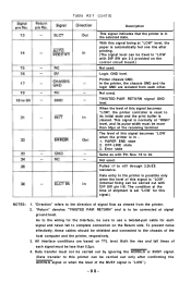
... print buffer is set "LOW' for each signal must be carried out by ignoring the ACKNLG or BUSY signal. (Data transfer to this signal becomes "LOW', the printer controller is reset to the chassis of shipment is cleared. Error state Same as viewed from each other. "Return" denotes "TWISTED PAIR RETURN" and is to the direction of this printer can be connected at "LOW" level, the paper...
... print buffer is set "LOW' for each signal must be carried out by ignoring the ACKNLG or BUSY signal. (Data transfer to this signal becomes "LOW', the printer controller is reset to the chassis of shipment is cleared. Error state Same as viewed from each other. "Return" denotes "TWISTED PAIR RETURN" and is to the direction of this printer can be connected at "LOW" level, the paper...


