
Operation Manual
Page 2
... Adjustment 34 9. Characteristics 2 INSTALLATION OF MX-80 TYPE II 3 1. Repacking steps 3 2. Removal of fanfold paper 27 7.1.3. Power Connection 15 INSTALLATION OF MX-80 F/T TYPE II 17 1. Dismounting of fanfold paper 25 7.1.2. Loading of Tractor Unit 24 7. Roll paper 29 7.2.1. Roll paper holder 29 7.2.2. Counting the Parts 3 3. Installation of the Printer 18 4. Installation of the Printer 5 4. Top of form position setting...
... Adjustment 34 9. Characteristics 2 INSTALLATION OF MX-80 TYPE II 3 1. Repacking steps 3 2. Removal of fanfold paper 27 7.1.3. Power Connection 15 INSTALLATION OF MX-80 F/T TYPE II 17 1. Dismounting of fanfold paper 25 7.1.2. Loading of Tractor Unit 24 7. Roll paper 29 7.2.1. Roll paper holder 29 7.2.2. Counting the Parts 3 3. Installation of the Printer 18 4. Installation of the Printer 5 4. Top of form position setting...
Operation Manual
Page 3
... 2. Preventive Maintenance 78 2. Parallel Interface 87 3. Setting of MX-80 Type II and MX-80 F/T Type II 83 2. Character designation codes 63 3.4. Dual-density bit image mode setting by ESC K + n1 + n2 68 4.2. Construction of DIP Switches 41 5.1. Printer initial check 38 2. Buzzer 39 3. Paper End Detector 39 4. Control Codes in the Bit Image Mode 67...
... 2. Preventive Maintenance 78 2. Parallel Interface 87 3. Setting of MX-80 Type II and MX-80 F/T Type II 83 2. Character designation codes 63 3.4. Dual-density bit image mode setting by ESC K + n1 + n2 68 4.2. Construction of DIP Switches 41 5.1. Printer initial check 38 2. Buzzer 39 3. Paper End Detector 39 4. Control Codes in the Bit Image Mode 67...

Operation Manual
Page 4
LIST OF FIGURES Fig. 1 EPSON MX-80 Type II and MX-80 F/T Type II Dot Matrix Printers ... 1 Fig. 2 Contents of Carton 4 Fig. 3 Laying Printer on Firm Surface 5 Fig. 4 Assembly Tools 6 Fig. 5 Removal of Shipping Screws 7 Fig. 6 Removal of Printer Lid 7 Fig. 7 Remounting of Printer Lid 8 Fig. 8 Cartridge Ribbon Setting 8 Fig. 9 Cartridge ... 10 Fig. 12 Insertion of Fanfold Paper 11 Fig. 13 Raising of Sprocket Lock Levers 12 Fig. 14 Engagement of Paper Feed Holes on Feeding Pins 12 Fig. 15 Printer with Fanfold Paper Set Completely 13 Fig. 16 Example of Paper Arrangement 13 Fig. 17 Top of...
LIST OF FIGURES Fig. 1 EPSON MX-80 Type II and MX-80 F/T Type II Dot Matrix Printers ... 1 Fig. 2 Contents of Carton 4 Fig. 3 Laying Printer on Firm Surface 5 Fig. 4 Assembly Tools 6 Fig. 5 Removal of Shipping Screws 7 Fig. 6 Removal of Printer Lid 7 Fig. 7 Remounting of Printer Lid 8 Fig. 8 Cartridge Ribbon Setting 8 Fig. 9 Cartridge ... 10 Fig. 12 Insertion of Fanfold Paper 11 Fig. 13 Raising of Sprocket Lock Levers 12 Fig. 14 Engagement of Paper Feed Holes on Feeding Pins 12 Fig. 15 Printer with Fanfold Paper Set Completely 13 Fig. 16 Example of Paper Arrangement 13 Fig. 17 Top of...

Operation Manual
Page 5
... Fig. Fig. 41 Alignment of Side Edges 32 Fig. 42 Form Position Setting Mark 32 Fig. 43 Print Area 3 2 Fig. 44 Setting of Cut Paper Sheet 33 Fig. 45 Printer with Cut Paper Sheet Set Completely 33 Fig. 46 Gap Adjustment 35 Fig. 47 Switches and Indicators on Control Panel 36 Fig. 48... Printer Initial Check 38 Fig. 49 Flowchart of Paper Out Status Release Procedure 39 Fig. 50 Removing Manual Paper Feed Knob 41 Fig. 51 Loosening All 4 Screws 41 Fig. 52 Pulling Out Wires Hooked to Control...
... Fig. Fig. 41 Alignment of Side Edges 32 Fig. 42 Form Position Setting Mark 32 Fig. 43 Print Area 3 2 Fig. 44 Setting of Cut Paper Sheet 33 Fig. 45 Printer with Cut Paper Sheet Set Completely 33 Fig. 46 Gap Adjustment 35 Fig. 47 Switches and Indicators on Control Panel 36 Fig. 48... Printer Initial Check 38 Fig. 49 Flowchart of Paper Out Status Release Procedure 39 Fig. 50 Removing Manual Paper Feed Knob 41 Fig. 51 Loosening All 4 Screws 41 Fig. 52 Pulling Out Wires Hooked to Control...
Operation Manual
Page 7
...In addition, various interface options are at your disposal. Fig. 1 EPSON MX-80 Type I I and MX-80 F/T Type I I Dot Matrix Printers -1- Introduction Ideal for computer business applications, the MX-80 Type II Dot Matrix Printer is common to the MX-80 Type II which is the latest extension of illustrations, graphs, charts, ...form feed, programmable line spacing and skip-over perforation are available to the hard-copy production of EPSON advanced printer technology. In this manual, installation of the printer control the carriage movement and paper feeding functions respectively.
...In addition, various interface options are at your disposal. Fig. 1 EPSON MX-80 Type I I and MX-80 F/T Type I I Dot Matrix Printers -1- Introduction Ideal for computer business applications, the MX-80 Type II Dot Matrix Printer is common to the MX-80 Type II which is the latest extension of illustrations, graphs, charts, ...form feed, programmable line spacing and skip-over perforation are available to the hard-copy production of EPSON advanced printer technology. In this manual, installation of the printer control the carriage movement and paper feeding functions respectively.

Operation Manual
Page 8
... from small business to home uses and even for graphic data processing are selectable by bidirectional printing with standard equipment including paper end detector, custom cartridge ribbon, etc. -2- page length setting in horizontal direction) modes are selectable under software control....x 106 characters. (6) 8 international character sets are freely available. automatic skip-over perforation - Characteristics The MX-80 Type II and MX-80 F/T Type II have been designed as a printer with initial setting to 11 or 12 inches. (b) Skip-over function selectable by DIP switch setting or ...
... from small business to home uses and even for graphic data processing are selectable by bidirectional printing with standard equipment including paper end detector, custom cartridge ribbon, etc. -2- page length setting in horizontal direction) modes are selectable under software control....x 106 characters. (6) 8 international character sets are freely available. automatic skip-over perforation - Characteristics The MX-80 Type II and MX-80 F/T Type II have been designed as a printer with initial setting to 11 or 12 inches. (b) Skip-over function selectable by DIP switch setting or ...

Operation Manual
Page 12
... the screws as described below. (See Fig. 5.) STEP 1. Before using the Printer, be sure to disassemble or assemble the printer. (1) Phillips type screwdriver 1 pc. (2) Round-blade type screwdriver 1 pc. Stand the printer on the underside of protective paper for paper end detector The MX-80 Type II is provided with a screwdriver, the two shipping screws visible on...
... the screws as described below. (See Fig. 5.) STEP 1. Before using the Printer, be sure to disassemble or assemble the printer. (1) Phillips type screwdriver 1 pc. (2) Round-blade type screwdriver 1 pc. Stand the printer on the underside of protective paper for paper end detector The MX-80 Type II is provided with a screwdriver, the two shipping screws visible on...
Operation Manual
Page 14
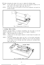
... onto the projection located at the center of the printer lid onto the left projection and push the printer lid down and set and remove. Cartridge Ribbon Setting EPSON's Cartridge Ribbon is touching. Open the printer lid (or remove it . Confirm that the scale (paper retainer) is turned toward the platen and is compact, long...
... onto the projection located at the center of the printer lid onto the left projection and push the printer lid down and set and remove. Cartridge Ribbon Setting EPSON's Cartridge Ribbon is touching. Open the printer lid (or remove it . Confirm that the scale (paper retainer) is turned toward the platen and is compact, long...
Operation Manual
Page 16
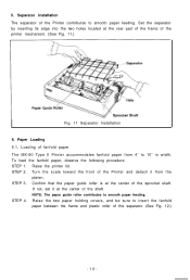
..., and be sure to 10" in width. Loading of fanfold paper The MX-80 Type II Printer accommodates fanfold paper from the platen. Confirm that the paper guide roller is at the center of the Printer contributes to smooth paper feeding. NOTE: The paper guide roller contributes to smooth paper feeding. Separator Installation The separator of the sprocket shaft. STEP...
..., and be sure to 10" in width. Loading of fanfold paper The MX-80 Type II Printer accommodates fanfold paper from the platen. Confirm that the paper guide roller is at the center of the Printer contributes to smooth paper feeding. NOTE: The paper guide roller contributes to smooth paper feeding. Separator Installation The separator of the sprocket shaft. STEP...
Operation Manual
Page 17
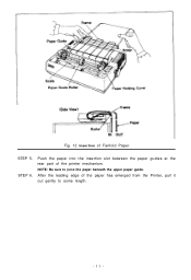
Push the paper into the insertion slot between the paper guides at the rear part of Fanfold Paper STEP 5. Fig. 12 Insertion of the printer mechanism. NOTE: Be sure to some length. -ll- After the leading edge of the paper has emerged from the Printer, pull it out gently to pass the paper beneath the upper paper guide. STEP 6.
Push the paper into the insertion slot between the paper guides at the rear part of Fanfold Paper STEP 5. Fig. 12 Insertion of the printer mechanism. NOTE: Be sure to some length. -ll- After the leading edge of the paper has emerged from the Printer, pull it out gently to pass the paper beneath the upper paper guide. STEP 6.

Operation Manual
Page 18
STEP 7. Fig. 14 Engagement of the paper. Then push the paper holding covers and the two sprocket lock levers down. (See Fig. 14.) NOTE: In this case, confirm that the feeding pins are centered in the respective paper feed holes of Paper Feed Holes on the feeding pins, push the scale back into position, and adjust the tension of Sprocket Lock Levers STEP 8. Raise the two sprocket lock levers to loosen, and adjust the sprocket pin position to the paper width. (See Fig. 13.) Fig. 13 Raising of the paper. Engage the paper feed holes of the paper on Feeding Pins -12-
STEP 7. Fig. 14 Engagement of the paper. Then push the paper holding covers and the two sprocket lock levers down. (See Fig. 14.) NOTE: In this case, confirm that the feeding pins are centered in the respective paper feed holes of Paper Feed Holes on the feeding pins, push the scale back into position, and adjust the tension of Sprocket Lock Levers STEP 8. Raise the two sprocket lock levers to loosen, and adjust the sprocket pin position to the paper width. (See Fig. 13.) Fig. 13 Raising of the paper. Engage the paper feed holes of the paper on Feeding Pins -12-

Operation Manual
Page 19
Fig. 15 Printer with the MX-80 Type II as shown below . (1) To disengage the paper from the paper holding mechanism, pull it forward out of the fanfold paper in parallel with Fanfold Paper Set Completely NOTE: When the MX-80 Type II is to be folded in the backward direction. (2) Feed the paper out of Paper Arrangement 6.2. NOTE: Do not attempt...
Fig. 15 Printer with the MX-80 Type II as shown below . (1) To disengage the paper from the paper holding mechanism, pull it forward out of the fanfold paper in parallel with Fanfold Paper Set Completely NOTE: When the MX-80 Type II is to be folded in the backward direction. (2) Feed the paper out of Paper Arrangement 6.2. NOTE: Do not attempt...
Operation Manual
Page 20
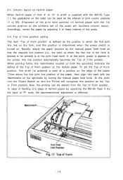
...be started from 4" to the printer, this point, turn the Power Switch on . To set the Top of Form position. If, at the extreme left of the print start position on fanfold paper with the MX-80 Type I I, the graduations on the fanfold paper. Alignment of the scale will recognize... this point, power is turned on and the Printer will facilitate column layout. 6.3.
...be started from 4" to the printer, this point, turn the Power Switch on . To set the Top of Form position. If, at the extreme left of the print start position on fanfold paper with the MX-80 Type I I, the graduations on the fanfold paper. Alignment of the scale will recognize... this point, power is turned on and the Printer will facilitate column layout. 6.3.

Operation Manual
Page 21
...primary AC rating different from the available power source, do not attempt to the 4th step. Paper Single-leaf paper Carbon paper sheets Position of the Printer. Power Connection The EPSON MX-80 Type II Dot Matrix Printer is capable of operating on the following three types of AC power. (1) 115V AC, 60Hz... (2) 220V AC, 50Hz (3) 240V AC, 50Hz Before connecting the MX-80 Type II to a power source...
...primary AC rating different from the available power source, do not attempt to the 4th step. Paper Single-leaf paper Carbon paper sheets Position of the Printer. Power Connection The EPSON MX-80 Type II Dot Matrix Printer is capable of operating on the following three types of AC power. (1) 115V AC, 60Hz... (2) 220V AC, 50Hz (3) 240V AC, 50Hz Before connecting the MX-80 Type II to a power source...
Operation Manual
Page 25
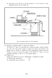
If the MX-80 F/T Type II is provided with a protective paper inserted between the inner and outer paper guides to protect the paper end detector from damage due to shocks or vibrations during transportation. Before using the Printer, be reshipped, remember to return it to the original position.... type screwdriver 1 pc. -19- (e) Avoid use of the Printer in humid locations or in the vicinity of protective paper for paper end detector The MX-80 F/T Type II is to be sure to remove this paper. Fig. 20 Laying Printer on Firm Surface (2) Removal of heat generating sources such as heater...
If the MX-80 F/T Type II is provided with a protective paper inserted between the inner and outer paper guides to protect the paper end detector from damage due to shocks or vibrations during transportation. Before using the Printer, be reshipped, remember to return it to the original position.... type screwdriver 1 pc. -19- (e) Avoid use of the Printer in humid locations or in the vicinity of protective paper for paper end detector The MX-80 F/T Type II is to be sure to remove this paper. Fig. 20 Laying Printer on Firm Surface (2) Removal of heat generating sources such as heater...
Operation Manual
Page 28
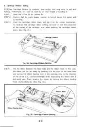
... (or remove it on the printer mechanism. STEP 2. Push the cartridge ribbon down . (See Fig. 24.) STEP 4. Put the ribbon between the head nose and the ribbon mask. Cartridge Ribbon Setting EPSON's Cartridge Ribbon is touching. STEP 1. Confirm that the scale (paper retainer) is turned toward the platen and is compact, long-lasting...
... (or remove it on the printer mechanism. STEP 2. Push the cartridge ribbon down . (See Fig. 24.) STEP 4. Put the ribbon between the head nose and the ribbon mask. Cartridge Ribbon Setting EPSON's Cartridge Ribbon is touching. STEP 1. Confirm that the scale (paper retainer) is turned toward the platen and is compact, long-lasting...

Operation Manual
Page 29
Set the separator by inserting its edge into the two holes located at the rear part of the frame of Correct and Incorrect Ribbon Setting 5. NOTES: 1. Fig. 26 Examples of the printer mechanism. (See Fig. 27.) I Fig. 27 Separator Installation -23- Incorrect setting of the Printer contributes to come off. (See Fig. 26.) 2. Separator Installation The separator of the ribbon may cause it to smooth paper feeding. Confirm that the ribbon is neither twisted nor creased and that the cartridge is set properly.
Set the separator by inserting its edge into the two holes located at the rear part of the frame of Correct and Incorrect Ribbon Setting 5. NOTES: 1. Fig. 26 Examples of the printer mechanism. (See Fig. 27.) I Fig. 27 Separator Installation -23- Incorrect setting of the Printer contributes to come off. (See Fig. 26.) 2. Separator Installation The separator of the ribbon may cause it to smooth paper feeding. Confirm that the ribbon is neither twisted nor creased and that the cartridge is set properly.

Operation Manual
Page 30
Release the lock levers of the tractor frames onto the shaft shown in Fig. 29 and then push down the tractor unit. Fig. 28 Dismounting of Tractor Unit To install the tractor unit, hook the notches of the tractor unit by pulling in Fig. 28. STEP 1. Keep pulling the levers and pull up the tractor unit. If it can be taken out as shown in the direction as follows; STEP 2. 6. Fig. 29 Mounting of the MX-80 F/T Type I I is an obstacle when using roll paper, it is detachable. Dismounting of Tractor Unit The tractor unit of Tractor Unit -24- .-
Release the lock levers of the tractor frames onto the shaft shown in Fig. 29 and then push down the tractor unit. Fig. 28 Dismounting of Tractor Unit To install the tractor unit, hook the notches of the tractor unit by pulling in Fig. 28. STEP 1. Keep pulling the levers and pull up the tractor unit. If it can be taken out as shown in the direction as follows; STEP 2. 6. Fig. 29 Mounting of the MX-80 F/T Type I I is an obstacle when using roll paper, it is detachable. Dismounting of Tractor Unit The tractor unit of Tractor Unit -24- .-

Operation Manual
Page 31
... fanfold paper The MX-80 F/T Type I I Printer accommodates fanfold paper from 4" to 10" in the direction of the arrow. (See Fig. 30.) STEP 3. Raise the printer lid. Unlock the release lever by pulling it in width. Raise the two paper holding covers, and be sure to some length. -25- STEP 5. NOTE: Be sure to smooth paper feeding. Adjust...
... fanfold paper The MX-80 F/T Type I I Printer accommodates fanfold paper from 4" to 10" in the direction of the arrow. (See Fig. 30.) STEP 3. Raise the printer lid. Unlock the release lever by pulling it in width. Raise the two paper holding covers, and be sure to some length. -25- STEP 5. NOTE: Be sure to smooth paper feeding. Adjust...

Operation Manual
Page 32
...the sprocket pin position to the paper width. (See Fig. 31.) STEP 6. Then push the paper holding covers and the two sprocket lock levers down. (See Fig. 32.) NOTE: In this case, confirm that the feeding pins are centered in the respective paper feed holes of Paper Feed Holes on the feeding ...pins, push the scale back into position, and adjust the tension of the paper. Do not lock the release lever. Engage the paper feed holes of the paper on Feeding Pins -26- STEP 8.
...the sprocket pin position to the paper width. (See Fig. 31.) STEP 6. Then push the paper holding covers and the two sprocket lock levers down. (See Fig. 32.) NOTE: In this case, confirm that the feeding pins are centered in the respective paper feed holes of Paper Feed Holes on the feeding ...pins, push the scale back into position, and adjust the tension of the paper. Do not lock the release lever. Engage the paper feed holes of the paper on Feeding Pins -26- STEP 8.
