
Operation Manual
Page 2
...Cut paper sheet 30 7.3.1. Power Connection 15 INSTALLATION OF MX-80 F/T TYPE II 17 1. Power Connection 34 -i- Installation of form position setting 14 7. Column layout on fanfold paper 28 7.1.4. Top of the Printer 5 4. Separator Installation 23 6. Loading of cut ...paper sheet 30 8. Column layout on fanfold paper 14 6.4. Gap Adjustment 34 9. Characteristics 2 INSTALLATION OF MX-80 TYPE II 3 1. Repacking steps 3 2. Unpacking steps 3 ...
...Cut paper sheet 30 7.3.1. Power Connection 15 INSTALLATION OF MX-80 F/T TYPE II 17 1. Power Connection 34 -i- Installation of form position setting 14 7. Column layout on fanfold paper 28 7.1.4. Top of the Printer 5 4. Separator Installation 23 6. Loading of cut ...paper sheet 30 8. Column layout on fanfold paper 14 6.4. Gap Adjustment 34 9. Characteristics 2 INSTALLATION OF MX-80 TYPE II 3 1. Repacking steps 3 2. Unpacking steps 3 ...
Operation Manual
Page 3
... n d n2 72 4.5. Construction of functional specifications 4 8 WHAT IS THE MX-80 TYPE II 52 1. Setting of DIP switch N O. 2 46 5.3. Setting of DIP Switches 41 5.1. Coding tables 47 5.4. What Is a Dot Matrix Printer 52 2. Control Codes in the Text Mode 56 3.1. Programming examples 73 MAINTENANCE ...78 1. Character Fonts 9 2 5. Printer initial check 38 2. Character designation codes 63 3.4. Normal-density bit ...
... n d n2 72 4.5. Construction of functional specifications 4 8 WHAT IS THE MX-80 TYPE II 52 1. Setting of DIP switch N O. 2 46 5.3. Setting of DIP Switches 41 5.1. Coding tables 47 5.4. What Is a Dot Matrix Printer 52 2. Control Codes in the Text Mode 56 3.1. Programming examples 73 MAINTENANCE ...78 1. Character Fonts 9 2 5. Printer initial check 38 2. Character designation codes 63 3.4. Normal-density bit ...

Operation Manual
Page 4
LIST OF FIGURES Fig. 1 EPSON MX-80 Type II and MX-80 F/T Type II Dot Matrix Printers ... 1 Fig. 2 Contents of Carton 4 Fig. 3 Laying Printer on Firm Surface 5 Fig. 4 Assembly Tools 6 Fig. 5 Removal of Shipping Screws 7 Fig. 6 Removal of Printer Lid 7 Fig. 7 Remounting of Printer Lid 8 Fig. 8 Cartridge Ribbon Setting 8 Fig. 9 Cartridge Ribbon Setting ...Fig. 31 Raising of Sprocket Lock Levers 26 Fig. 32 Engagement of Paper Feed Holes on Feeding Pins 26 Fig. 33 Printer with Fanfold Paper Set Completely 27 Fig. 34 Example of Paper Arrangement 27 Fig. 35 Top of Form Position Setting 28 ...
LIST OF FIGURES Fig. 1 EPSON MX-80 Type II and MX-80 F/T Type II Dot Matrix Printers ... 1 Fig. 2 Contents of Carton 4 Fig. 3 Laying Printer on Firm Surface 5 Fig. 4 Assembly Tools 6 Fig. 5 Removal of Shipping Screws 7 Fig. 6 Removal of Printer Lid 7 Fig. 7 Remounting of Printer Lid 8 Fig. 8 Cartridge Ribbon Setting 8 Fig. 9 Cartridge Ribbon Setting ...Fig. 31 Raising of Sprocket Lock Levers 26 Fig. 32 Engagement of Paper Feed Holes on Feeding Pins 26 Fig. 33 Printer with Fanfold Paper Set Completely 27 Fig. 34 Example of Paper Arrangement 27 Fig. 35 Top of Form Position Setting 28 ...

Operation Manual
Page 5
...Fig. 43 Print Area 3 2 Fig. 44 Setting of Cut Paper Sheet 33 Fig. 45 Printer with Cut Paper Sheet Set Completely 33 Fig. 46 Gap Adjustment 35 Fig. 47 Switches and Indicators on Control ...Panel 36 Fig. 48 Printer Initial Check 38 Fig. 49 Flowchart of Paper Out Status Release Procedure 39 Fig. 50 Removing Manual... All 4 Screws 41 Fig. 52 Pulling Out Wires Hooked to Control Panel 42 Fig. 53 Construction of Type II Printer 43 Fig. 54 Location of DIP Switches 4 4 Fig. 55 Setting DIP Switches 4 4 Fig. 56 Setting Amount...
...Fig. 43 Print Area 3 2 Fig. 44 Setting of Cut Paper Sheet 33 Fig. 45 Printer with Cut Paper Sheet Set Completely 33 Fig. 46 Gap Adjustment 35 Fig. 47 Switches and Indicators on Control ...Panel 36 Fig. 48 Printer Initial Check 38 Fig. 49 Flowchart of Paper Out Status Release Procedure 39 Fig. 50 Removing Manual... All 4 Screws 41 Fig. 52 Pulling Out Wires Hooked to Control Panel 42 Fig. 53 Construction of Type II Printer 43 Fig. 54 Location of DIP Switches 4 4 Fig. 55 Setting DIP Switches 4 4 Fig. 56 Setting Amount...
Operation Manual
Page 7
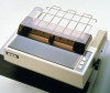
..., a friction and adjustable sprocket feed type called "MX-80 F/T Type II" is its capability of EPSON advanced printer technology. In addition, various interface options are at your disposal. This printer also offers 40-, 66-, 80-, and 132-column printing widths. Fig. 1 EPSON MX-80 Type I I and MX-80 F/T Type I I Dot Matrix Printers -1- Another important feature of the MX-80 Type II is also available.
..., a friction and adjustable sprocket feed type called "MX-80 F/T Type II" is its capability of EPSON advanced printer technology. In addition, various interface options are at your disposal. This printer also offers 40-, 66-, 80-, and 132-column printing widths. Fig. 1 EPSON MX-80 Type I I and MX-80 F/T Type I I Dot Matrix Printers -1- Another important feature of the MX-80 Type II is also available.

Operation Manual
Page 8
Characteristics The MX-80 Type II and MX-80 F/T Type II have been designed as a printer with standard equipment including paper end detector, custom cartridge ribbon, etc. -2- The following is possible, with logic seeking capability. (5) Easy... automatic skip-over function selectable by DIP switch setting or variable by software. (c) Programmable line spacing. (d) Vertical tabulation and horizontal tabulation (e) Buzzer, printer select/deselect function. (4) High throughput by DIP switch setting or software. (7) Complete with versatile functions to 11 or 12 inches. (b) Skip-over ...
Characteristics The MX-80 Type II and MX-80 F/T Type II have been designed as a printer with standard equipment including paper end detector, custom cartridge ribbon, etc. -2- The following is possible, with logic seeking capability. (5) Easy... automatic skip-over function selectable by DIP switch setting or variable by software. (c) Programmable line spacing. (d) Vertical tabulation and horizontal tabulation (e) Buzzer, printer select/deselect function. (4) High throughput by DIP switch setting or software. (7) Complete with versatile functions to 11 or 12 inches. (b) Skip-over ...
Operation Manual
Page 9
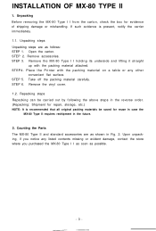
... by following the above steps in the future. 2. Remove accessories. STEP 3. Place the Printer with the packing material attached. Take off the packing material carefully. Unpacking Before removing the MX-80 Type I I as soon as follows: STEP 1. Remove the MX-80 Type I I holding its underside and lifting it straight up with the packing material on...
... by following the above steps in the future. 2. Remove accessories. STEP 3. Place the Printer with the packing material attached. Take off the packing material carefully. Unpacking Before removing the MX-80 Type I I as soon as follows: STEP 1. Remove the MX-80 Type I I holding its underside and lifting it straight up with the packing material on...
Operation Manual
Page 10
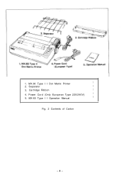
Power Cord (Only European Type 220/240V) 1 5. MX-80 Type I I Operation Manual 1 Fig. 2 Contents of Carton -4- Cartridge Ribbon 1 4. 1. Separator 1 3. MX-80 Type I I Dot Matrix Printer 1 2.
Power Cord (Only European Type 220/240V) 1 5. MX-80 Type I I Operation Manual 1 Fig. 2 Contents of Carton -4- Cartridge Ribbon 1 4. 1. Separator 1 3. MX-80 Type I I Dot Matrix Printer 1 2.

Operation Manual
Page 11
NOTE: Rubber feet are provided to prevent the marring of the surface on which the MX-80 Type I I is placed. (b) Avoid operating the MX-80 Type I I , observe the following instructions. (a) Place the Printer on Firm Surface 3. Your layout may cause the malfunction of the print head. (c) Connect the power ...enough room for the separator in the air. Installation of the Printer (1) Operating site selection When installing the MX-80 Type I I in places where it may be exposed to extreme shock. (e) Avoid use of the Printer in humid locations or in the vicinity of greasy dust exists in...
NOTE: Rubber feet are provided to prevent the marring of the surface on which the MX-80 Type I I is placed. (b) Avoid operating the MX-80 Type I I , observe the following instructions. (a) Place the Printer on Firm Surface 3. Your layout may cause the malfunction of the print head. (c) Connect the power ...enough room for the separator in the air. Installation of the Printer (1) Operating site selection When installing the MX-80 Type I I in places where it may be exposed to extreme shock. (e) Avoid use of the Printer in humid locations or in the vicinity of greasy dust exists in...

Operation Manual
Page 12
...of the shipping screws is to protect the MX-80 Type II against any damage that may be reshipped, remember to return it to the original position. (3) Prepare tools Prepare the following two tools to remove this paper. Stand the printer on the underside of the lower case. ...-6- STEP 2. Before using the Printer, be sure to disassemble or assemble the printer. (1) Phillips type screwdriver 1 pc. (2) Round-blade type screwdriver 1 pc. (2) Removal of protective paper for paper end detector The MX-80 Type II is provided with a screwdriver, the two shipping ...
...of the shipping screws is to protect the MX-80 Type II against any damage that may be reshipped, remember to return it to the original position. (3) Prepare tools Prepare the following two tools to remove this paper. Stand the printer on the underside of the lower case. ...-6- STEP 2. Before using the Printer, be sure to disassemble or assemble the printer. (1) Phillips type screwdriver 1 pc. (2) Round-blade type screwdriver 1 pc. (2) Removal of protective paper for paper end detector The MX-80 Type II is provided with a screwdriver, the two shipping ...
Operation Manual
Page 13
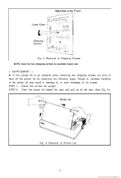
STEP 1. STEP 2. Push the printer lid toward the right and pull up its hinges. Stand the printer lid upright. Rough or careless handling of Printer Lid -7- Right Side of the Printer Fig. 5 Removal of Shipping Screws NOTE: Save the two shipping screws for possible future use. < SUPPLEMENT > l If the printer lid is an obstacle when removing the shipping screws, be sure to , or even breakage of, its left side. (See Fig. 6.) Fig. 6 Removal of the printer lid may result in damage to take off the printer lid by observing the following steps.
STEP 1. STEP 2. Push the printer lid toward the right and pull up its hinges. Stand the printer lid upright. Rough or careless handling of Printer Lid -7- Right Side of the Printer Fig. 5 Removal of Shipping Screws NOTE: Save the two shipping screws for possible future use. < SUPPLEMENT > l If the printer lid is an obstacle when removing the shipping screws, be sure to , or even breakage of, its left side. (See Fig. 6.) Fig. 6 Removal of the printer lid may result in damage to take off the printer lid by observing the following steps.
Operation Manual
Page 14
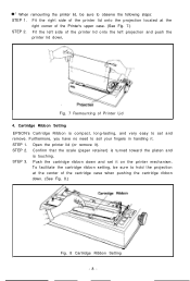
... STEP 3. Cartridge Ribbon Setting EPSON's Cartridge Ribbon is touching. Push the cartridge ribbon down , Fig. 7 Remounting of the printer lid onto the left projection and push the printer lid down and set and remove. STEP 1. Fit the left side of Printer Lid 4. When remounting the printer lid, be sure to set... it ). To facilitate the cartridge ribbon setting, be sure to soil your fingers in handling it. Open the printer lid (or remove it on the printer mechanism. Confirm that the scale (paper retainer) is turned toward the platen and is compact, long-lasting, and ...
... STEP 3. Cartridge Ribbon Setting EPSON's Cartridge Ribbon is touching. Push the cartridge ribbon down , Fig. 7 Remounting of the printer lid onto the left projection and push the printer lid down and set and remove. STEP 1. Fit the left side of Printer Lid 4. When remounting the printer lid, be sure to set... it ). To facilitate the cartridge ribbon setting, be sure to soil your fingers in handling it. Open the printer lid (or remove it on the printer mechanism. Confirm that the scale (paper retainer) is turned toward the platen and is compact, long-lasting, and ...
Operation Manual
Page 16
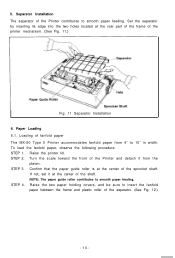
... to smooth paper feeding. Raise the two paper holding covers, and be sure to smooth paper feeding. Separator Installation The separator of the Printer contributes to insert the fanfold paper between the frame and plastic roller of the separator. (See Fig. 12.) -10- NOTE: The ... the front of the Printer and detach it at the center of the printer mechanism. (See Fig. 11.) Fig. 11 Separator Installation 6. STEP 1. Raise the printer lid. STEP 3. Confirm that the paper guide roller is at the center of fanfold paper The MX-80 Type II Printer accommodates fanfold paper from...
... to smooth paper feeding. Raise the two paper holding covers, and be sure to smooth paper feeding. Separator Installation The separator of the Printer contributes to insert the fanfold paper between the frame and plastic roller of the separator. (See Fig. 12.) -10- NOTE: The ... the front of the Printer and detach it at the center of the printer mechanism. (See Fig. 11.) Fig. 11 Separator Installation 6. STEP 1. Raise the printer lid. STEP 3. Confirm that the paper guide roller is at the center of fanfold paper The MX-80 Type II Printer accommodates fanfold paper from...
Operation Manual
Page 17
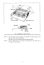
STEP 6. Fig. 12 Insertion of the paper has emerged from the Printer, pull it out gently to pass the paper beneath the upper paper guide. NOTE: Be sure to some length. -ll- After the leading edge of Fanfold Paper STEP 5. Push the paper into the insertion slot between the paper guides at the rear part of the printer mechanism.
STEP 6. Fig. 12 Insertion of the paper has emerged from the Printer, pull it out gently to pass the paper beneath the upper paper guide. NOTE: Be sure to some length. -ll- After the leading edge of Fanfold Paper STEP 5. Push the paper into the insertion slot between the paper guides at the rear part of the printer mechanism.

Operation Manual
Page 19
...in the backward direction. (2) Feed the paper out of the printer by electrical operation. Fig. 16 Example of the Printer. STEP 9. Fig. 15 Printer with Fanfold Paper Set Completely NOTE: When the MX-80 Type II is to be folded in parallel with the MX-80 Type II as shown below . (1) To disengage the paper ...from the paper holding mechanism, pull it forward out of Paper Arrangement 6.2. NOTE: Do not attempt to be used on a desk or a bench, arrangement of the fanfold paper in an accordion style. Put the printer lid on ...
...in the backward direction. (2) Feed the paper out of the printer by electrical operation. Fig. 16 Example of the Printer. STEP 9. Fig. 15 Printer with Fanfold Paper Set Completely NOTE: When the MX-80 Type II is to be folded in parallel with the MX-80 Type II as shown below . (1) To disengage the paper ...from the paper holding mechanism, pull it forward out of Paper Arrangement 6.2. NOTE: Do not attempt to be used on a desk or a bench, arrangement of the fanfold paper in an accordion style. Put the printer lid on ...
Operation Manual
Page 20
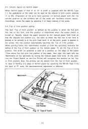
... the Top of the print start position on fanfold paper with the matchmarks on the sprockets by the input of Form position on and the Printer will facilitate column layout. Namely, adjust the paper position by adjusting it to 10" in which the first line of Form position. 6.3. When printing forms... on the scale can be started from 4" to these indexes of Form position. In case of feeding one page of fanfold paper by operating the MX-80 Type II by turning the manual paper feed knob. Top of form position setting The term "Top of Form position" is defined as the position...
... the Top of the print start position on fanfold paper with the matchmarks on the sprockets by the input of Form position on and the Printer will facilitate column layout. Namely, adjust the paper position by adjusting it to 10" in which the first line of Form position. 6.3. When printing forms... on the scale can be started from 4" to these indexes of Form position. In case of feeding one page of fanfold paper by operating the MX-80 Type II by turning the manual paper feed knob. Top of form position setting The term "Top of Form position" is defined as the position...

Operation Manual
Page 21
... within the area two lines each above and below the perforation. 8. If your MX-80 Type II has a primary AC rating different from the store where you purchased the MX-80 Type I I. -15- Power Connection The EPSON MX-80 Type II Dot Matrix Printer is used, be used to adjust the printing pressure as well as to adjust...
... within the area two lines each above and below the perforation. 8. If your MX-80 Type II has a primary AC rating different from the store where you purchased the MX-80 Type I I. -15- Power Connection The EPSON MX-80 Type II Dot Matrix Printer is used, be used to adjust the printing pressure as well as to adjust...
Operation Manual
Page 23
... storage, etc.) NOTE: It is present, notify the carrier immediately. 1.1. Place the Printer with the packing material attached. STEP 5. Repacking steps Repacking can be saved for reuse in case the MX-80 F/T Type I I by following the above steps in the reverse order. (Repacking: ...Shipment for evidence of shipping damage or mishandling. Unpacking steps Unpacking steps are as shown in the future. 2. Remove the MX-80 F/T Type I I requires reshipment in Fig. 19. STEP 4. STEP 2. STEP 6. Upon unpacking, if you notice any other convenient flat surface...
... storage, etc.) NOTE: It is present, notify the carrier immediately. 1.1. Place the Printer with the packing material attached. STEP 5. Repacking steps Repacking can be saved for reuse in case the MX-80 F/T Type I I by following the above steps in the reverse order. (Repacking: ...Shipment for evidence of shipping damage or mishandling. Unpacking steps Unpacking steps are as shown in the future. 2. Remove the MX-80 F/T Type I I requires reshipment in Fig. 19. STEP 4. STEP 2. STEP 6. Upon unpacking, if you notice any other convenient flat surface...

Operation Manual
Page 24
... I , observe the following instructions. (a) Place the Printer on which the MX-80 F/T Type I I Operation Manual 1 Fig. 19 Contents of greasy dust exists in the air. Installation of the Printer (1) Operating site selection When installing the MX-80 F/T Type I I in temperature, or to direct sunlight...operation, to sudden changes in places where it may be exposed to extreme shock. -18- 1. MX-80 F/T Type I I is placed. (b) Avoid operating the MX-80 F/T Type. MX-80 F/T Type II Dot Matrix Printer 1 2. Power Cord (Only European Type 220/24OV) 1 5. Separator 1 3. NOTE: Greasy ...
... I , observe the following instructions. (a) Place the Printer on which the MX-80 F/T Type I I Operation Manual 1 Fig. 19 Contents of greasy dust exists in the air. Installation of the Printer (1) Operating site selection When installing the MX-80 F/T Type I I in temperature, or to direct sunlight...operation, to sudden changes in places where it may be exposed to extreme shock. -18- 1. MX-80 F/T Type I I is placed. (b) Avoid operating the MX-80 F/T Type. MX-80 F/T Type II Dot Matrix Printer 1 2. Power Cord (Only European Type 220/24OV) 1 5. Separator 1 3. NOTE: Greasy ...
Operation Manual
Page 25
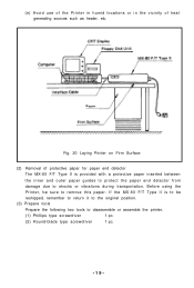
... of heat generating sources such as heater, etc. If the MX-80 F/T Type II is provided with a protective paper inserted between the inner and outer paper guides to protect the paper end detector from damage due to disassemble or assemble the printer. (1) Phillips type screwdriver 1 pc. (2) Round-blade type... position. (3) Prepare tools Prepare the following two tools to shocks or vibrations during transportation. (e) Avoid use of the Printer in humid locations or in the vicinity of protective paper for paper end detector The MX-80 F/T Type II is to be sure to remove this paper.
... of heat generating sources such as heater, etc. If the MX-80 F/T Type II is provided with a protective paper inserted between the inner and outer paper guides to protect the paper end detector from damage due to disassemble or assemble the printer. (1) Phillips type screwdriver 1 pc. (2) Round-blade type... position. (3) Prepare tools Prepare the following two tools to shocks or vibrations during transportation. (e) Avoid use of the Printer in humid locations or in the vicinity of protective paper for paper end detector The MX-80 F/T Type II is to be sure to remove this paper.


