Technical Brief (Impact Printers)
Page 1
... their respective owners. Impact printers are capable of printing. or a 24-pin printer, and whether it is a registered trademark of Seiko Epson Corporation. 1/00 Other trademarks are renowned for their reliability with LQ FX-980-Nine-pin narrow carriage Wide carriage printers have 4 number in their names Narrow carriage printers have finer printhead pins which : Hit the...
... their respective owners. Impact printers are capable of printing. or a 24-pin printer, and whether it is a registered trademark of Seiko Epson Corporation. 1/00 Other trademarks are renowned for their reliability with LQ FX-980-Nine-pin narrow carriage Wide carriage printers have 4 number in their names Narrow carriage printers have finer printhead pins which : Hit the...
Product Support Bulletin(s)
Page 1
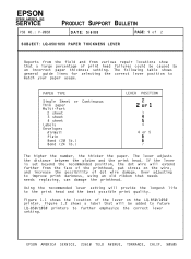
... a .1 second pause between beeps. Carriage will stop until the printhead cools down. LQ-500, LQ-510, LQ-1010, LQ-850, LQ-950, LQ-1050, L1000, AP-4000, AP-4500 1 beep: BEL code (.5 sec beep) 1 beep: A Control Panel setting is over heated. EPSON AMERICA, INC. LQ-200/AP-3000 1 beep: BEL code 1 beep: A Control...tones when certain error conditions exist. The following error codes are of the beeps issued by the printers are listed by product name. EPSON Product Support Bulletin Subject: 24 Pin Printer Error and Beep Codes Date: 4/3/91 Page(s): 1 of three beeps. Where the beeps or ...
... a .1 second pause between beeps. Carriage will stop until the printhead cools down. LQ-500, LQ-510, LQ-1010, LQ-850, LQ-950, LQ-1050, L1000, AP-4000, AP-4500 1 beep: BEL code (.5 sec beep) 1 beep: A Control Panel setting is over heated. EPSON AMERICA, INC. LQ-200/AP-3000 1 beep: BEL code 1 beep: A Control...tones when certain error conditions exist. The following error codes are of the beeps issued by the printers are listed by product name. EPSON Product Support Bulletin Subject: 24 Pin Printer Error and Beep Codes Date: 4/3/91 Page(s): 1 of three beeps. Where the beeps or ...
Product Support Bulletin(s)
Page 4
...upon loading a single sheet paper, the paper has skewed. NOTES: Error codes 11 and 12 are usually caused by turning the printer off, taking out the paper and turning the printer back on. Both features were added to the SRAM has failed. Errors 0,2, 3, 10, and 20 may cause errors 10 or...not detected at power up b. Both of 4 LQ-2550 cont. 03 A 'Verify After Write" check to ensure proper paper handling and prevent paper jams, which can result in the Service Manual (page A-54, figure A-52) and on TIB LQ2550-005. This is a printhead wire protection feature. (2) PE sensor may have failed...
...upon loading a single sheet paper, the paper has skewed. NOTES: Error codes 11 and 12 are usually caused by turning the printer off, taking out the paper and turning the printer back on. Both features were added to the SRAM has failed. Errors 0,2, 3, 10, and 20 may cause errors 10 or...not detected at power up b. Both of 4 LQ-2550 cont. 03 A 'Verify After Write" check to ensure proper paper handling and prevent paper jams, which can result in the Service Manual (page A-54, figure A-52) and on TIB LQ2550-005. This is a printhead wire protection feature. (2) PE sensor may have failed...
Product Support Bulletin(s)
Page 12
... locations show that a large percentage of the lever on the wire, and increase the possibility of dot wire damage. If the lever is set beyond the recommended position, the dot wire will provide the longest life to the print head and the best possible print quality. Figure...label that needs needs replacing, can damage the printhead. The lever adjusts the distance between the platen and the print head. Figure 1.1 shows the location of print head failures could be added to future LQ-850/1050 printers to match your paper usage. EPSON AMERICA SERVICE, 23610 TELO AVENUE, TORRANCE, CALIF...
... locations show that a large percentage of the lever on the wire, and increase the possibility of dot wire damage. If the lever is set beyond the recommended position, the dot wire will provide the longest life to the print head and the best possible print quality. Figure...label that needs needs replacing, can damage the printhead. The lever adjusts the distance between the platen and the print head. Figure 1.1 shows the location of print head failures could be added to future LQ-850/1050 printers to match your paper usage. EPSON AMERICA SERVICE, 23610 TELO AVENUE, TORRANCE, CALIF...

Technical Manual
Page 7
...Tear-Off Function 1. -23 1.9.3 Micro-Adjustment Top-of the FX-850/1050 1-1 Figure 1-2. Exterior Views of -Form (TOF) Set Function . . 1-23 1.10 PAPER END DETECTION 1. -24 1.11 MAIN COMPONENTS 1. . -25 1.11.1 Printer Mechanism 1. -26 1.11.2 PEGX Board (Main Board 1-27 1.11.3... PEBFIL-11 Board (Filter Board) and Power Transformer 1. -28 1.11.4 PGPNL Board (Control Panel 1-29 1.11.5 Housing 1. .-31 LIST OF FIGURES Figure 1-1. Printhead Pin Configuration 1-3 l-i
...Tear-Off Function 1. -23 1.9.3 Micro-Adjustment Top-of the FX-850/1050 1-1 Figure 1-2. Exterior Views of -Form (TOF) Set Function . . 1-23 1.10 PAPER END DETECTION 1. -24 1.11 MAIN COMPONENTS 1. . -25 1.11.1 Printer Mechanism 1. -26 1.11.2 PEGX Board (Main Board 1-27 1.11.3... PEBFIL-11 Board (Filter Board) and Power Transformer 1. -28 1.11.4 PGPNL Board (Control Panel 1-29 1.11.5 Housing 1. .-31 LIST OF FIGURES Figure 1-1. Printhead Pin Configuration 1-3 l-i
Technical Manual
Page 12
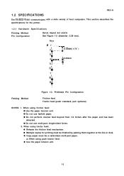
... - -- - - 0.35mm ( 1/72" ) - ~1 T 4 4 --- -- -- --0.29mm 51 ' - - Printhead Pin Configuration Feeding Method Friction feed Tractor feed (push: standard, pull: optional) NOTES: 1. q Do not perform reverse feed beyond than 1/6 inches after the paper end has been detected. q Multiple copies for the printer. 1.2.1 Hardware Specifications Printing Method Pin Configuration Serial, impact dot matrix See Figure 1-2 (diameter: 0.29 mm... carbonless multi-part paper. This section describes the specifications for printing must be finished by pasting them together at the line or dots.
... - -- - - 0.35mm ( 1/72" ) - ~1 T 4 4 --- -- -- --0.29mm 51 ' - - Printhead Pin Configuration Feeding Method Friction feed Tractor feed (push: standard, pull: optional) NOTES: 1. q Do not perform reverse feed beyond than 1/6 inches after the paper end has been detected. q Multiple copies for the printer. 1.2.1 Hardware Specifications Printing Method Pin Configuration Serial, impact dot matrix See Figure 1-2 (diameter: 0.29 mm... carbonless multi-part paper. This section describes the specifications for printing must be finished by pasting them together at the line or dots.

Technical Manual
Page 18
... POH (duty 25%) FX-105O: 6000 POH (duty 25%) 100 million characters (14 dots/character) 1-9 Table 1-11. Electrical Specifications See Table 1-12. Table 1-12. Table 1-13. Dimensions Weight FX-850 FX-I Reliability MCBF MTBF Printhead life 5 million lines (excluding printhead) (MCBF . . . Electrical Specifications - 120 V Version 220/240 V Version Voltage [V AC] 120V * 10YO 220...
... POH (duty 25%) FX-105O: 6000 POH (duty 25%) 100 million characters (14 dots/character) 1-9 Table 1-11. Electrical Specifications See Table 1-12. Table 1-12. Table 1-13. Dimensions Weight FX-850 FX-I Reliability MCBF MTBF Printhead life 5 million lines (excluding printhead) (MCBF . . . Electrical Specifications - 120 V Version 220/240 V Version Voltage [V AC] 120V * 10YO 220...

Technical Manual
Page 31
.... q An internal DC voltage drop is detected (abnormal voltage is shorted. Upper Address RAM (IC) Short circuited printhead drive transistor Beeps 10 times, pausing after the printer mechanism has been initialized (carriage error). q The carriage home signal is not detected after every beep. q During ... set OFF LINE using the ON LINE switch. q The printer is detected during printing (carriage error). q The carriage home position is set and paper loading has been completed (paper end state). 1-22 q The printhead is moved outside of the printable area by a READ/WRITE...
.... q An internal DC voltage drop is detected (abnormal voltage is shorted. Upper Address RAM (IC) Short circuited printhead drive transistor Beeps 10 times, pausing after the printer mechanism has been initialized (carriage error). q The carriage home signal is not detected after every beep. q During ... set OFF LINE using the ON LINE switch. q The printer is detected during printing (carriage error). q The carriage home position is set and paper loading has been completed (paper end state). 1-22 q The printhead is moved outside of the printable area by a READ/WRITE...

Technical Manual
Page 34
PEGX Board Paper Feed Motor Carriage Motor FX-850 FX-1 050 NOTE: In FX-850, the paper tension unit and push tractor unit are excluded. 1.11 MAIN COMPONENTS The FX-850/l 050 printer includes the following major subassemblies: q Model-3B 10\3B60 printer mechanism q PEGX board (main board) q PGPNL board (control panel) q PEBFIL-11 board (filter board) and power transformer q Housing Figure 1-11 shows the FX-850/l 050 component locations. - Board Paper T e n s i o n= Unit Plunger- Component Locations 1-25 Figure 1-11. Printhead - Power Transformer FIEV.-A PEBFIL-ll-
PEGX Board Paper Feed Motor Carriage Motor FX-850 FX-1 050 NOTE: In FX-850, the paper tension unit and push tractor unit are excluded. 1.11 MAIN COMPONENTS The FX-850/l 050 printer includes the following major subassemblies: q Model-3B 10\3B60 printer mechanism q PEGX board (main board) q PGPNL board (control panel) q PEBFIL-11 board (filter board) and power transformer q Housing Figure 1-11 shows the FX-850/l 050 component locations. - Board Paper T e n s i o n= Unit Plunger- Component Locations 1-25 Figure 1-11. Printhead - Power Transformer FIEV.-A PEBFIL-ll-

Technical Manual
Page 36
...board are: Universal IC q STK6722HZ (IC2A Carriage Motor Driver q NJM2355 (lCIA Switching Regulator IC Gate Array q E05A15HA (IC3A Paper Feed and Carriage Motors controller, and Printhead driver q E05A16GA (IC7A Host computer interface Memory IC q EP-ROM (IC4A Program ROM, 256 K-bit q S-RAM (IC5A and 6A Buffer and Back up memory... features very compact construction. Other main ICS on this board. Since the complicated logic circuit section is the main board, and interfaces the printer to the host computer, controls the printer mechanism and control panel, and supplies DC voltage.
...board are: Universal IC q STK6722HZ (IC2A Carriage Motor Driver q NJM2355 (lCIA Switching Regulator IC Gate Array q E05A15HA (IC3A Paper Feed and Carriage Motors controller, and Printhead driver q E05A16GA (IC7A Host computer interface Memory IC q EP-ROM (IC4A Program ROM, 256 K-bit q S-RAM (IC5A and 6A Buffer and Back up memory... features very compact construction. Other main ICS on this board. Since the complicated logic circuit section is the main board, and interfaces the printer to the host computer, controls the printer mechanism and control panel, and supplies DC voltage.

Technical Manual
Page 41
CHAPTER 2 OPERATING PRINCIPLES 2.1 GENERAL 2. .-.1 2.1.1 Cable Connections 2. -1 2.2 PRINTER MECHANISM OPERATION 2-3 2.2.1 Printhead 2. .-4 2.2.2 Carriage Mechanism 2-5 2.2.3 Home Position Sensor 2-5 2.2.4 Ribbon Feed Mechanism 2. -6 2.2.5 Paper Feed Mechanism 2. -7 2.2.5.1 Push Tractor Feeding Method 2-8 2.2.5.2 Friciton Feeding Method 2-9 2.3 CIRCUIT OPERATION 2. . -10 2.3.1 General Information 2. -1o 2.3.1.1 Power ...
CHAPTER 2 OPERATING PRINCIPLES 2.1 GENERAL 2. .-.1 2.1.1 Cable Connections 2. -1 2.2 PRINTER MECHANISM OPERATION 2-3 2.2.1 Printhead 2. .-4 2.2.2 Carriage Mechanism 2-5 2.2.3 Home Position Sensor 2-5 2.2.4 Ribbon Feed Mechanism 2. -6 2.2.5 Paper Feed Mechanism 2. -7 2.2.5.1 Push Tractor Feeding Method 2-8 2.2.5.2 Friciton Feeding Method 2-9 2.3 CIRCUIT OPERATION 2. . -10 2.3.1 General Information 2. -1o 2.3.1.1 Power ...

Technical Manual
Page 42
Cable Connections 2. -1 Print Mechanism Block Diagram 2-3 Printhead Mechanism 2. -4 Carriage Mechanism 2. -5 Ribbon Feed Mechanism 2. -6 Push Tractor Feeding Method 2-8 Friction Feeding Method 2. -9 ...Interface Control Circuit Block Diagram 2-34 Z.ii REV.-A 2.3.4.5 Printer Error Detection 2-39 2.3.5 Printer Mechanism Control 2-41 2.3.5.1 Carriage Control Circuit 2-41 2.3.5.2 Carriage Motor Software Control 2-49 2.3.5.3 Paper Feed Control Circuit 2-53 2.3.5.4 Plunger Drive Circuit 2-58 2.3.5.5 Printhead Control Circuit 2-60 LIST OF FIGURES Figure 2-1. Vx Voltage...
Cable Connections 2. -1 Print Mechanism Block Diagram 2-3 Printhead Mechanism 2. -4 Carriage Mechanism 2. -5 Ribbon Feed Mechanism 2. -6 Push Tractor Feeding Method 2-8 Friction Feeding Method 2. -9 ...Interface Control Circuit Block Diagram 2-34 Z.ii REV.-A 2.3.4.5 Printer Error Detection 2-39 2.3.5 Printer Mechanism Control 2-41 2.3.5.1 Carriage Control Circuit 2-41 2.3.5.2 Carriage Motor Software Control 2-49 2.3.5.3 Paper Feed Control Circuit 2-53 2.3.5.4 Plunger Drive Circuit 2-58 2.3.5.5 Printhead Control Circuit 2-60 LIST OF FIGURES Figure 2-1. Vx Voltage...

Technical Manual
Page 43
...-up Circuit 2. -38 Figure 2-33. Carriage Motor Drive Sequence 2-45 Figure 2-38. Home Position Seek Phase States 2-52 Figure 2-43. Half-dot Protection Circuit 2. -62 REV.-A LIST OF TABLES Table 2-1. ST-RAM Conditions 2. -38 Table 2-7. 2-2 phase Excitation 2. -46 Table 2-8. 1-2... phase Excitation 2.-4. 6 Table 2-9. Figure 2-29. High Speed Skip Operation 2-50 Figure 2-41. Printhead Central Circuit Block Diagram 2-60 Figure 2-51. Carriage Speed Modes 2. -49 Table 2-10. GA(E05A15HA) Operation Diagram 2-42 Figure 2-35. Home...
...-up Circuit 2. -38 Figure 2-33. Carriage Motor Drive Sequence 2-45 Figure 2-38. Home Position Seek Phase States 2-52 Figure 2-43. Half-dot Protection Circuit 2. -62 REV.-A LIST OF TABLES Table 2-1. ST-RAM Conditions 2. -38 Table 2-7. 2-2 phase Excitation 2. -46 Table 2-8. 1-2... phase Excitation 2.-4. 6 Table 2-9. Figure 2-29. High Speed Skip Operation 2-50 Figure 2-41. Printhead Central Circuit Block Diagram 2-60 Figure 2-51. Carriage Speed Modes 2. -49 Table 2-10. GA(E05A15HA) Operation Diagram 2-42 Figure 2-35. Home...

Technical Manual
Page 46
PEGX board CN4 Drives the printhead needles. 12 Table A-1 8 '(,.' Transfers the state of the connectors on 2 Table A-2 1 the PEGX... plunger that opens and shuts the 2 paper bail on the PEGX board. Used CN2 for data transfer from the printer mechanism to the con- 3 Table A-20 trol circuit on the 2 PEGX board. When 26 the optional interface ... paper feed motor. 6 Drives the carriage motor. 9 Transfers the state of the release lever from the printer mechanism to one of the paper end sensor from the host computer. Interface connector between the PEGX board 20...
PEGX board CN4 Drives the printhead needles. 12 Table A-1 8 '(,.' Transfers the state of the connectors on 2 Table A-2 1 the PEGX... plunger that opens and shuts the 2 paper bail on the PEGX board. Used CN2 for data transfer from the printer mechanism to the con- 3 Table A-20 trol circuit on the 2 PEGX board. When 26 the optional interface ... paper feed motor. 6 Drives the carriage motor. 9 Transfers the state of the release lever from the printer mechanism to one of the paper end sensor from the host computer. Interface connector between the PEGX board 20...
Technical Manual
Page 47
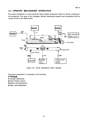
... the PEGX board. Platen v r I Cantrol Circuit Feed Motor Ribbon Feed I )Kl + + Home Position CN6 Printhead Drive Circuit ( O Carriage Motor Carriage Motor Control Circuit Figure 2-2. Printer Mechanism Block Diagram The printer mechanism is a 9-pin serial dot matrix impact mechanism. Figure 2-2 shows a drawing of the following: q Printhead q Carriage Mechanism q Home Position Sensor q Ribbon Feed Mechanism q Paper Feed Mechanism 2-3
... the PEGX board. Platen v r I Cantrol Circuit Feed Motor Ribbon Feed I )Kl + + Home Position CN6 Printhead Drive Circuit ( O Carriage Motor Carriage Motor Control Circuit Figure 2-2. Printer Mechanism Block Diagram The printer mechanism is a 9-pin serial dot matrix impact mechanism. Figure 2-2 shows a drawing of the following: q Printhead q Carriage Mechanism q Home Position Sensor q Ribbon Feed Mechanism q Paper Feed Mechanism 2-3

Technical Manual
Page 48
... is printed by the printhead drive circuit. Printhead Mechanism 2-4 REV.-A 2.2.1 Printhead *P*,.-~, The printhead is converted into dot-image data for one vertical row, and output to print a dot pattern on the PEGX board is an electromagnetic induction 9-pin serial dot head. Nine dot wires are driven individually to the printhead by serially printing the dot patterns for each vertical row...
... is printed by the printhead drive circuit. Printhead Mechanism 2-4 REV.-A 2.2.1 Printhead *P*,.-~, The printhead is converted into dot-image data for one vertical row, and output to print a dot pattern on the PEGX board is an electromagnetic induction 9-pin serial dot head. Nine dot wires are driven individually to the printhead by serially printing the dot patterns for each vertical row...

Technical Manual
Page 55
... and the smoothing circuit, and is converted to approximately 36 VDC by the transformer, and is divided into the DC voltage required to drive the printer mechanism and operate the control circuits. The +36 VDC and +5 VDC are supplied to the control circuit. This circuit converts the AC voltage from ...Paper feed motor holding voltage Signal pull-up voltage +36V (vu) Plunger solenoid driving voltage Paper feed motor driving voltage Carriage motor driving voltage +24V I Printhead driving voltage (Vp) Option interface voltage + 12V - 12V Option interface voltage 2-11 ,,
... and the smoothing circuit, and is converted to approximately 36 VDC by the transformer, and is divided into the DC voltage required to drive the printer mechanism and operate the control circuits. The +36 VDC and +5 VDC are supplied to the control circuit. This circuit converts the AC voltage from ...Paper feed motor holding voltage Signal pull-up voltage +36V (vu) Plunger solenoid driving voltage Paper feed motor driving voltage Carriage motor driving voltage +24V I Printhead driving voltage (Vp) Option interface voltage + 12V - 12V Option interface voltage 2-11 ,,
Technical Manual
Page 57
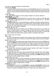
... circuit The printhead drive circuit drives the printhead after expanding the printhead data. The CPU begins executing the program from the host computer is processed and expanded so that the values will remain valid when the printer power is controlled by outputting the phase switching signal generated by ...and Super/subscript characters so that command processing speed is improved and the load on or when the I NIT signal is converted to dot data for parallel data (including the optional interface), the control panel, plunger, speed of the head data buffer, carriage home position sensor...
... circuit The printhead drive circuit drives the printhead after expanding the printhead data. The CPU begins executing the program from the host computer is processed and expanded so that the values will remain valid when the printer power is controlled by outputting the phase switching signal generated by ...and Super/subscript characters so that command processing speed is improved and the load on or when the I NIT signal is converted to dot data for parallel data (including the optional interface), the control panel, plunger, speed of the head data buffer, carriage home position sensor...

Technical Manual
Page 72
Table 2-3. FX-850/1050 : 14.74 MHz Ground Analog port ground Vp (+ 24VDC) monitor port Vu (+ 36VDC) monitor port Printhead short-circuit monitor port DIP switch 2-1 to 2-3 - IN - Main power sourse NOTE: "Direction" on the signal flow is as viewed from the CPU. 2-28 Pin ...
Table 2-3. FX-850/1050 : 14.74 MHz Ground Analog port ground Vp (+ 24VDC) monitor port Vu (+ 36VDC) monitor port Printhead short-circuit monitor port DIP switch 2-1 to 2-3 - IN - Main power sourse NOTE: "Direction" on the signal flow is as viewed from the CPU. 2-28 Pin ...

Technical Manual
Page 73
... driving signal I I (Head Data 1-8) 23 HD8 OUT 24 Vss - In addition, the gate array controls the carriage motor and paper feed motor, and drives the printhead and plunger solenoids. Logic Ground 25 Vss REV.-A 2.3.3.2 E05A15HA Gate Array Functions This gate array performs chip selection for the main components on the gate...
... driving signal I I (Head Data 1-8) 23 HD8 OUT 24 Vss - In addition, the gate array controls the carriage motor and paper feed motor, and drives the printhead and plunger solenoids. Logic Ground 25 Vss REV.-A 2.3.3.2 E05A15HA Gate Array Functions This gate array performs chip selection for the main components on the gate...


