Product Support Bulletin(s)
Page 1
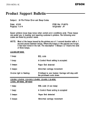
... and repairing customer's printers. Where the beeps or the pauses are of 4 PSB No: P-0076 Originator JV Epson printers issue beep tones when certain error conditions exist. The description "3 Beeps x 2" means two sets of three beeps. Carriage will stop until the printhead cools down. LQ-200/... carriage movement On-Line light is flashing: Printhead is accepted 3 beeps: Paper End detected 5 beeps: Abnormal carriage movement LQ-500, LQ-510, LQ-1010, LQ-850, LQ-950, LQ-1050, L1000, AP-4000, AP-4500 1 beep: BEL code (.5 sec beep) 1 beep: A Control Panel setting is over heated...
... and repairing customer's printers. Where the beeps or the pauses are of 4 PSB No: P-0076 Originator JV Epson printers issue beep tones when certain error conditions exist. The description "3 Beeps x 2" means two sets of three beeps. Carriage will stop until the printhead cools down. LQ-200/... carriage movement On-Line light is flashing: Printhead is accepted 3 beeps: Paper End detected 5 beeps: Abnormal carriage movement LQ-500, LQ-510, LQ-1010, LQ-850, LQ-950, LQ-1050, L1000, AP-4000, AP-4500 1 beep: BEL code (.5 sec beep) 1 beep: A Control Panel setting is over heated...
Product Support Bulletin(s)
Page 4
...is a motor control error. Both of these errors are documented in printhead failures. PSB No: P-0076 Page: 4 of 4 LQ-2550 cont. 03 A 'Verify After Write" check to ensure proper paper handling and prevent paper jams, which can result in ... switching error d. NOTES: Error codes 11 and 12 are usually caused by turning the printer off, taking out the paper and turning the printer back on the ROMA board may cause errors 10 or 20. The SRAM could be bad...and 20 may have failed or is a printhead wire protection feature. (2) PE sensor may require a repair, adjustment or replacement.
...is a motor control error. Both of these errors are documented in printhead failures. PSB No: P-0076 Page: 4 of 4 LQ-2550 cont. 03 A 'Verify After Write" check to ensure proper paper handling and prevent paper jams, which can result in ... switching error d. NOTES: Error codes 11 and 12 are usually caused by turning the printer off, taking out the paper and turning the printer back on the ROMA board may cause errors 10 or 20. The SRAM could be bad...and 20 may have failed or is a printhead wire protection feature. (2) PE sensor may require a repair, adjustment or replacement.
Product Support Bulletin(s)
Page 12
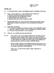
... the possibility of the lever on the LQ-850/1050 printer. Figure 1.1 shows the location of dot wire damage. If the lever is set beyond the recommended position, the dot wire will provide the longest life to match your paper usage. EPSON AMERICA SERVICE, 23610 TELO AVENUE, TORRANCE,...will extend further from various repair locations show that a large percentage of print head failures could be added to future LQ-850/1050 printers to improve print darkness, using an old ribbon that will be caused by an incorrect paper thickness setting. EPSON EPSON AMERICA, INC. The lever...
... the possibility of the lever on the LQ-850/1050 printer. Figure 1.1 shows the location of dot wire damage. If the lever is set beyond the recommended position, the dot wire will provide the longest life to match your paper usage. EPSON AMERICA SERVICE, 23610 TELO AVENUE, TORRANCE,...will extend further from various repair locations show that a large percentage of print head failures could be added to future LQ-850/1050 printers to improve print darkness, using an old ribbon that will be caused by an incorrect paper thickness setting. EPSON EPSON AMERICA, INC. The lever...

Technical Manual
Page 3
...components of the FX-850 and FX- 1050. q The contents of printer operation. Chapter 6 - REV.-A PREFACE This manual describes functions, theory of electrical and mechanical operations, maintenance, and repair of the printer. The chapters are subject to change without... notice. - Includes a step-by-step guide for troubleshooting. Provides Epson-approved techniques for product disassembly, assembly, and adjustment. Chapter 3 ...
...components of the FX-850 and FX- 1050. q The contents of printer operation. Chapter 6 - REV.-A PREFACE This manual describes functions, theory of electrical and mechanical operations, maintenance, and repair of the printer. The chapters are subject to change without... notice. - Includes a step-by-step guide for troubleshooting. Provides Epson-approved techniques for product disassembly, assembly, and adjustment. Chapter 3 ...

Technical Manual
Page 5
... AS ANTI-STATIC WRIST STRAPS, WHEN ACCESSING INTERNAL COMPONENTS. 5. The precautionary measures itemized below should be observed when performing repair/maintenance procedures. REPAIRS ON EPSON PRODUCT SHOULD BE PERFORMED ONLY BY AN EPSON CERTIFIED REPAIR TECHNICIAN. 2. MAKE CERTAIN THAT THE SOURCE VOLTAGE IS THE SAME AS THE RATED VOLTAGE, LISTED ON THE SERIAL NUMBERIRATING PLATE...
... AS ANTI-STATIC WRIST STRAPS, WHEN ACCESSING INTERNAL COMPONENTS. 5. The precautionary measures itemized below should be observed when performing repair/maintenance procedures. REPAIRS ON EPSON PRODUCT SHOULD BE PERFORMED ONLY BY AN EPSON CERTIFIED REPAIR TECHNICIAN. 2. MAKE CERTAIN THAT THE SOURCE VOLTAGE IS THE SAME AS THE RATED VOLTAGE, LISTED ON THE SERIAL NUMBERIRATING PLATE...
Technical Manual
Page 110
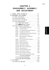
CHAPTER 4 DISASSEMBLY, ASSEMBLY, AND ADJUSTMENT 4.1 GENERAL REPAIR INFORMATION 4. -1 4.2 DISASSEMBLY AND ASSEMBLY 4. -5 4.2.1 Upper Case Removal 4. -7 4.2.2 Control Panel Removal 4. -8 4.2.3 Push Tractor Unit Removal 4. -8 4.2.4 Circuit Board Removal 4-9 4.2.4.1 PEGX Board Removal 4-9 4.2.4.2 PEBFIL-11 Board Removal 4-11 4.2.5 Printer Mechanism Disassembly 4-12 4.2.5.1 Printer Mechanism Removal 4-13 4.2.5.2 Printhead Removal 4-14 4.2.5.3 FPC (Flexible Printed Cable) Removal ......... 4-15 4.2.5.4 Carriage Motor Removal 4-16 4.2.5.5 Timing...
CHAPTER 4 DISASSEMBLY, ASSEMBLY, AND ADJUSTMENT 4.1 GENERAL REPAIR INFORMATION 4. -1 4.2 DISASSEMBLY AND ASSEMBLY 4. -5 4.2.1 Upper Case Removal 4. -7 4.2.2 Control Panel Removal 4. -8 4.2.3 Push Tractor Unit Removal 4. -8 4.2.4 Circuit Board Removal 4-9 4.2.4.1 PEGX Board Removal 4-9 4.2.4.2 PEBFIL-11 Board Removal 4-11 4.2.5 Printer Mechanism Disassembly 4-12 4.2.5.1 Printer Mechanism Removal 4-13 4.2.5.2 Printhead Removal 4-14 4.2.5.3 FPC (Flexible Printed Cable) Removal ......... 4-15 4.2.5.4 Carriage Motor Removal 4-16 4.2.5.5 Timing...
Technical Manual
Page 114
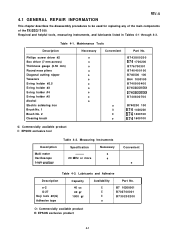
4.1 GENERAL REPAIR INFORMATION REV.-A This chapter describes the disassembly procedures to be used for replacing any of the main components of the FX-850\l 050. Table 4-1. ...No. B743800200 B74 1700200 B776700301 B740400100 B740500 100 B64 1000100 B740900400 B740800500 B740800600 B740800700 o B740200 100 0 B74 1400200 0 B74 1400100 o B74 1600100 o: Commercially available product E: EPSON exclusive tool Description Multi meter Oscilloscope Logic analizer Table 4-2. Maintenance Tools Description Philips screw driver #2 Box driver (7 mm across) Thickness gauge (0.50 mm) Round nose...
4.1 GENERAL REPAIR INFORMATION REV.-A This chapter describes the disassembly procedures to be used for replacing any of the main components of the FX-850\l 050. Table 4-1. ...No. B743800200 B74 1700200 B776700301 B740400100 B740500 100 B64 1000100 B740900400 B740800500 B740800600 B740800700 o B740200 100 0 B74 1400200 0 B74 1400100 o B74 1600100 o: Commercially available product E: EPSON exclusive tool Description Multi meter Oscilloscope Logic analizer Table 4-2. Maintenance Tools Description Philips screw driver #2 Box driver (7 mm across) Thickness gauge (0.50 mm) Round nose...
Technical Manual
Page 150
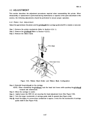
... (Refer to Section 4.2.5.2.). Step 5: Move the carriage to center. Step 7: Turn the larger countersink of the parts described in this printer. Ribbon Mask Holder and Ribbon Mask Configuration Step 4: Reinstall the printhead on the carriage. Step 6: Lighty loosen the HNO (4) nut securing the head adjustment lever (... B (See Figure 4-55). 4-37 Step 8: Insert the blade of a screw driver (a diameter is rotated or removed. When disassembly or replacement is performed during maintenance or repaires of carriage guide shaft B upward (See Figure 4-55). l.).
... (Refer to Section 4.2.5.2.). Step 5: Move the carriage to center. Step 7: Turn the larger countersink of the parts described in this printer. Ribbon Mask Holder and Ribbon Mask Configuration Step 4: Reinstall the printhead on the carriage. Step 6: Lighty loosen the HNO (4) nut securing the head adjustment lever (... B (See Figure 4-55). 4-37 Step 8: Insert the blade of a screw driver (a diameter is rotated or removed. When disassembly or replacement is performed during maintenance or repaires of carriage guide shaft B upward (See Figure 4-55). l.).

Technical Manual
Page 157
... 5-8 Unit Parts List 5. .-9 Symptom and Reference Pages 5-1o Power Supply Circuit Parts List 5-17 Power Supply Circuit Unit Repair 5-18 Control Circuit Parts List 5. -20 Electric Device List 5. -20 5-i Figure 5-6. Table 5-8. Figure 5-3. CHAPTER 5...Programmer Tips 5. . -8 5 . 3 U N I T REPLACEMENT 5. .-9 5 . 4 U N I T REPAIR 5. . -. 17 5.4.1 Power Supply Circuit 5. -17 5.4.2 Control Circuit 5. .-20 5.4.3 Model-3Bl O/3B60 Printer Mechanism 5-20 REV.-A LIST OF FIGURES Figure 5-1. Troubleshooting Procedure 5-1 System Overview 5. -2 Initial Screen 5. .-3 Menu Screen ...
... 5-8 Unit Parts List 5. .-9 Symptom and Reference Pages 5-1o Power Supply Circuit Parts List 5-17 Power Supply Circuit Unit Repair 5-18 Control Circuit Parts List 5. -20 Electric Device List 5. -20 5-i Figure 5-6. Table 5-8. Figure 5-3. CHAPTER 5...Programmer Tips 5. . -8 5 . 3 U N I T REPLACEMENT 5. .-9 5 . 4 U N I T REPAIR 5. . -. 17 5.4.1 Power Supply Circuit 5. -17 5.4.2 Control Circuit 5. .-20 5.4.3 Model-3Bl O/3B60 Printer Mechanism 5-20 REV.-A LIST OF FIGURES Figure 5-1. Troubleshooting Procedure 5-1 System Overview 5. -2 Initial Screen 5. .-3 Menu Screen ...

Technical Manual
Page 158
... to perform troubleshooting, as shown in the printer. Troubleshooting Tools Tool No. #648 Item Diagnostic Tool Description Use together with EPSON PC (EQUITY)\QX-16 Part No. Table... 5-1. B765 109701 5-1 Here, a simple procedure is not easy to section 5,3, 1 I =3 Refer to section 5,3 Unit Replacement Refer to perform. Troubleshooting Procedure Table 5-1 lists the troubleshooting tools contained in Figure 5-1. 1 Refer to section 5,2 Foult check using the diagnostic tool 1 I PEGX board component repair Printer Mechonism ports repair...
... to perform troubleshooting, as shown in the printer. Troubleshooting Tools Tool No. #648 Item Diagnostic Tool Description Use together with EPSON PC (EQUITY)\QX-16 Part No. Table... 5-1. B765 109701 5-1 Here, a simple procedure is not easy to section 5,3, 1 I =3 Refer to section 5,3 Unit Replacement Refer to perform. Troubleshooting Procedure Table 5-1 lists the troubleshooting tools contained in Figure 5-1. 1 Refer to section 5,2 Foult check using the diagnostic tool 1 I PEGX board component repair Printer Mechonism ports repair...
Technical Manual
Page 159
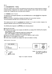
... uses ranging from repair and analysis to the complex nature of the printer. System Overview 5-2 B765 109701 PDOS For FX-850/1050 with IBM-PC/QX-l 6 Expertise with MS-DOS, one flexible disk containing the programs, and a diagnostics ROM. REV.-A 5.2 DIAGNOSTIC TOOL Due to testing. 5.2.2 System Overview HOST COMPUTER (MS-DOS) EPSON PC/QX...
... uses ranging from repair and analysis to the complex nature of the printer. System Overview 5-2 B765 109701 PDOS For FX-850/1050 with IBM-PC/QX-l 6 Expertise with MS-DOS, one flexible disk containing the programs, and a diagnostics ROM. REV.-A 5.2 DIAGNOSTIC TOOL Due to testing. 5.2.2 System Overview HOST COMPUTER (MS-DOS) EPSON PC/QX...

Technical Manual
Page 161
.... Manual Mode Menu Screen As shown in Figure 5-5, the menu mode displays all test file names in the diagnostics mode. DIAGNOSTICS PROGRAM FOR FX-850/1050 1. TEST PRINT MODE 5. HEX 02: TEMP. HEX 03: COLUMN. REV.-A Next, press any key to your needs. MANUAL MODE 2. Each mode is ...on the menu screen. AUTO MODE WITH OSCILLOSCOPE 4. In addition, since this mode enables the user to input a signal from which the level of repair or the type of diagnostics to be executed. AUTO FILE MODE 3. RETURN TO SYSTEM (MS-DOS) PLEASE SELECT MODE (1 TO 5)=? The results indicating...
.... Manual Mode Menu Screen As shown in Figure 5-5, the menu mode displays all test file names in the diagnostics mode. DIAGNOSTICS PROGRAM FOR FX-850/1050 1. TEST PRINT MODE 5. HEX 02: TEMP. HEX 03: COLUMN. REV.-A Next, press any key to your needs. MANUAL MODE 2. Each mode is ...on the menu screen. AUTO MODE WITH OSCILLOSCOPE 4. In addition, since this mode enables the user to input a signal from which the level of repair or the type of diagnostics to be executed. AUTO FILE MODE 3. RETURN TO SYSTEM (MS-DOS) PLEASE SELECT MODE (1 TO 5)=? The results indicating...

Technical Manual
Page 162
...displayed on the screen. All of the files shown in Figures 5-5 are finished, the suspected part is the question. q After the unit has been repaired. After the checks are executed. TO CHECK THE REFERENCE VOLTAGE OF A/D CONVERTER: IS THE VOLTAGE LEVEL OF IC7B (CPU) PIN42 ABOUT + 5V?=...results in conjunction with an oscilloscope. The user observes waveforms and voltages on the oscilloscope by following cases: q When the cause of the printer checks sequentially. To leave this part of the test press the 'ESC KEY' To return to find a malfunctioning part without electronic or ...
...displayed on the screen. All of the files shown in Figures 5-5 are finished, the suspected part is the question. q After the unit has been repaired. After the checks are executed. TO CHECK THE REFERENCE VOLTAGE OF A/D CONVERTER: IS THE VOLTAGE LEVEL OF IC7B (CPU) PIN42 ABOUT + 5V?=...results in conjunction with an oscilloscope. The user observes waveforms and voltages on the oscilloscope by following cases: q When the cause of the printer checks sequentially. To leave this part of the test press the 'ESC KEY' To return to find a malfunctioning part without electronic or ...

Technical Manual
Page 163
... Checks the height lag during actual printing. Bit Image Mode. This mode is useful for irregular printing or paper feeding. After repairing the printer, this mode can select the printer types, interface types, and mode of test print. Down Load Printing. Wire (Pin) Check. Etc. =CG Table check ...f=: This mode is used to check dot alignment. You can perform various test operations. Draft mode (10, 12, 15 Pitch) Roman Mode (10,...
... Checks the height lag during actual printing. Bit Image Mode. This mode is useful for irregular printing or paper feeding. After repairing the printer, this mode can select the printer types, interface types, and mode of test print. Down Load Printing. Wire (Pin) Check. Etc. =CG Table check ...f=: This mode is used to check dot alignment. You can perform various test operations. Draft mode (10, 12, 15 Pitch) Roman Mode (10,...

Technical Manual
Page 174
If (2) control circuit, or (3) printer mechanism need repair, use the diagnostic tool introduced in Section 5.2. 5.4.1 Power Supply Circuit This section indicates possible causes and checkpoints for different of the printer mechanism. Description Pulse width modulation control Diode Bridge 100V, 6A 80V, 500mA, 600mW 60V, 10A 60V, 5A Fuse 250V, 3 15A Fuse 125V, 2A Fuse...
If (2) control circuit, or (3) printer mechanism need repair, use the diagnostic tool introduced in Section 5.2. 5.4.1 Power Supply Circuit This section indicates possible causes and checkpoints for different of the printer mechanism. Description Pulse width modulation control Diode Bridge 100V, 6A 80V, 500mA, 600mW 60V, 10A 60V, 5A Fuse 250V, 3 15A Fuse 125V, 2A Fuse...

Technical Manual
Page 175
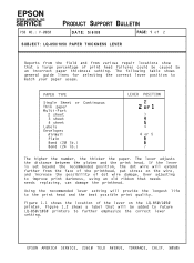
Cause IC 1A is defective. o U_u IOV/DIV, 20/.Ls/DlV Chopping Waveform (Emitter of IC 1A) Transistors Q 12 and Q 13 are defective. Solution Replace IC 1A o klllzk IV/DIV, 20@DlV Oscillation Waveform (pin 2 of IC 1A) obllu 10V/DIV, 20ps/DIV Switching Waveform (Pin 9 of Q13) 5-18 Power Supply Circuit Unit Repair Symptom The +5V dead. Observe the chopping waveform Replace Q12 or Q13. Check Point Observe the oscillation waveform and the switching waveform. REV.-A Table 5-6.
Cause IC 1A is defective. o U_u IOV/DIV, 20/.Ls/DlV Chopping Waveform (Emitter of IC 1A) Transistors Q 12 and Q 13 are defective. Solution Replace IC 1A o klllzk IV/DIV, 20@DlV Oscillation Waveform (pin 2 of IC 1A) obllu 10V/DIV, 20ps/DIV Switching Waveform (Pin 9 of Q13) 5-18 Power Supply Circuit Unit Repair Symptom The +5V dead. Observe the chopping waveform Replace Q12 or Q13. Check Point Observe the oscillation waveform and the switching waveform. REV.-A Table 5-6.

Technical Manual
Page 176
Power Supply Circuit Unit Repair (cent'd) Cause IC 1A is turned on. Switching Waveform (Pin 1.1 of IC 1A) Observe the chopping wave form Lnn_ll o Replace Q1O or al 1 IOV/DIV, ... or ZD1 O. T k!k!lzk o IV/DIV, 20/.Ls/DlV Oscillation Waveform (Pin 2 of Q1 O) Vx voltage is not Q23, Q30, and Observe the Vx voltage, when printer power is defective.
Power Supply Circuit Unit Repair (cent'd) Cause IC 1A is turned on. Switching Waveform (Pin 1.1 of IC 1A) Observe the chopping wave form Lnn_ll o Replace Q1O or al 1 IOV/DIV, ... or ZD1 O. T k!k!lzk o IV/DIV, 20/.Ls/DlV Oscillation Waveform (Pin 2 of Q1 O) Vx voltage is not Q23, Q30, and Observe the Vx voltage, when printer power is defective.

Technical Manual
Page 177
..., 1.5W 100V, 3A, 1.2W 120V, 5A, 1.5W 60V, 150mA, 400mW 50V, 150mA, 400mW 5.4.3 Model-3 B10/3B60 Printer Mechanism Use the diagnostic tooI to identify the problem. REV.-A 5.3.2 Control Circuit The control circuit can be repaired using the diagnostic tool to detect malfunctions among the carriage motor, paper-feed motor, and sensor, Table...
..., 1.5W 100V, 3A, 1.2W 120V, 5A, 1.5W 60V, 150mA, 400mW 50V, 150mA, 400mW 5.4.3 Model-3 B10/3B60 Printer Mechanism Use the diagnostic tooI to identify the problem. REV.-A 5.3.2 Control Circuit The control circuit can be repaired using the diagnostic tool to detect malfunctions among the carriage motor, paper-feed motor, and sensor, Table...
