Product Information Guide
Page 3
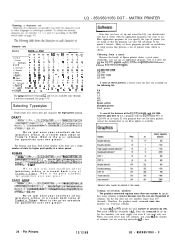
DRAFT !"#$%&'()*t,- ./0123456789:;~=>?@ABCDEFGHIJK LMNOPPRSTUVWXYZ[\]A-'abcdefg^hi.j_k^lm. Choosing a character set LQ - 850/950/1050 DOT - See page 9-3 I [^A\].A^.-l'aaBbcodo^eo.fg.u.hu^iy.jk.~.lUm~ngo~p~qri~...Latm America f $ d ; 6 (, i ii i ?I R%e; s ^ ' Ii ) - 0 Japan x$e[Y; ^ ' 1 : t - 3 Norway * 0 t d o4uciToiiti 10 Denmark II f $ gROAUlsa?oiti 11 Span u * g & ; nopqrstuv We've just seen your excellent ad for miniature zebras in a recent back issue of dots for higher print quality at a lower speed. MATRIX PRINTER Character sets Country ASClt coda Ihex) OUSA 1 ...
DRAFT !"#$%&'()*t,- ./0123456789:;~=>?@ABCDEFGHIJK LMNOPPRSTUVWXYZ[\]A-'abcdefg^hi.j_k^lm. Choosing a character set LQ - 850/950/1050 DOT - See page 9-3 I [^A\].A^.-l'aaBbcodo^eo.fg.u.hu^iy.jk.~.lUm~ngo~p~qri~...Latm America f $ d ; 6 (, i ii i ?I R%e; s ^ ' Ii ) - 0 Japan x$e[Y; ^ ' 1 : t - 3 Norway * 0 t d o4uciToiiti 10 Denmark II f $ gROAUlsa?oiti 11 Span u * g & ; nopqrstuv We've just seen your excellent ad for miniature zebras in a recent back issue of dots for higher print quality at a lower speed. MATRIX PRINTER Character sets Country ASClt coda Ihex) OUSA 1 ...
Product Support Bulletin(s)
Page 16
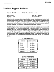
... Bulletin Subject: Quick Reference for the 24 pin printers are averages while printing in tenths of the human ear. EPSON AMERICA, INC. The acoustic noise levels for Printer Acoustic Noise Levels Date: 6/5/91 Page(s): 1 of 2 PSB No: P-0016D Originator: SLS Sound intensity is a list of current product... levels for the 9 pin printers are not guaranteed figures. 9 PIN PRINTERS MODEL I LX-810 FX-850 FX-1050 I DFX-5000 I DFX-8000 1 NOISE LEVEL 56 dB(A) II 56 dB(A) 56 dB(A) I 55 dB(A) II I 55 dB(A) II 24 PIN PRINTERS LQ-510 56 dB(A) LQ-1010 56 dB(A) 11 LQ-850 1 56 dB(A) 11...
... Bulletin Subject: Quick Reference for the 24 pin printers are averages while printing in tenths of the human ear. EPSON AMERICA, INC. The acoustic noise levels for Printer Acoustic Noise Levels Date: 6/5/91 Page(s): 1 of 2 PSB No: P-0016D Originator: SLS Sound intensity is a list of current product... levels for the 9 pin printers are not guaranteed figures. 9 PIN PRINTERS MODEL I LX-810 FX-850 FX-1050 I DFX-5000 I DFX-8000 1 NOISE LEVEL 56 dB(A) II 56 dB(A) 56 dB(A) I 55 dB(A) II I 55 dB(A) II 24 PIN PRINTERS LQ-510 56 dB(A) LQ-1010 56 dB(A) 11 LQ-850 1 56 dB(A) 11...

User Manual
Page 55
... line, press this button to feed the paper one line, or hold it if paper is loaded. -BIN 1/BIN 2 When the printer is on line, the indicator - When the printer is off line status. light is on line, press this button to load paper if paper is not loaded, or to eject... feed the paper continuously. Buttons Operating the Control Panel 0 MULTI.PART SelecType 0 POWER 0 READY 3 PAPER OUT 0 SANS SERIF 0 SLOT A 0 SLOT B FORM FEED- 0 1s CPI ---I 0 CONDENSE0 II-. ON LINE This button controls the printer's on the optional dual bin cut sheet feeder. 3-3
... line, press this button to feed the paper one line, or hold it if paper is loaded. -BIN 1/BIN 2 When the printer is on line, the indicator - When the printer is off line status. light is on line, press this button to load paper if paper is not loaded, or to eject... feed the paper continuously. Buttons Operating the Control Panel 0 MULTI.PART SelecType 0 POWER 0 READY 3 PAPER OUT 0 SANS SERIF 0 SLOT A 0 SLOT B FORM FEED- 0 1s CPI ---I 0 CONDENSE0 II-. ON LINE This button controls the printer's on the optional dual bin cut sheet feeder. 3-3

User Manual
Page 72
... on page 3-8. Set the DIP switch, and then turn off , reset, or intialized. it remains valid even after the printer is 0 # $ @ o \ II # $ # $ America It $ B IE 0 6 ; To obtain the desired character set, set provides you with the characters used in each character set ; R # ... 2 Germany 3 U.K. 4 Denmark I 5 Sweden 6 Italy 7 Spain I 8 Japan 9 Norway 10 Denmark 11 Spain II 12 Latin 64 Legal #$@E\ # $ ii o G # $ 5 x u f B 0 # tl B is turned off the printer. Software commands however, override DIP switch settings until they are available only through 12 and 64 are cancelled or the...
... on page 3-8. Set the DIP switch, and then turn off , reset, or intialized. it remains valid even after the printer is 0 # $ @ o \ II # $ # $ America It $ B IE 0 6 ; To obtain the desired character set, set provides you with the characters used in each character set ; R # ... 2 Germany 3 U.K. 4 Denmark I 5 Sweden 6 Italy 7 Spain I 8 Japan 9 Norway 10 Denmark 11 Spain II 12 Latin 64 Legal #$@E\ # $ ii o G # $ 5 x u f B 0 # tl B is turned off the printer. Software commands however, override DIP switch settings until they are available only through 12 and 64 are cancelled or the...
User Manual
Page 162
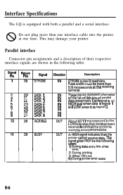
...goes HIGH in the following cases: 1) During data entry (ea. Interface Specifications The LQ is ready to read data. Pulse width must be more than 0.5 microseconds at one interface cable into the printer 8 at the receiving terminal. Do not plug more than one time. This may ...in the following table. LOW indicates that data has been received and that the printer cannot receive data. Signal Pin 1 Return Pin 19 Signal STROBE 20 DATA 1 : DATA 2 4 22: DATA 3 DATA 4 : 2 DATA 5 25 DATA 6 ii DATA 7 9 2 DATA 8 10 28 ACKNLG 11 29 BUSY Direction Description ...
...goes HIGH in the following cases: 1) During data entry (ea. Interface Specifications The LQ is ready to read data. Pulse width must be more than 0.5 microseconds at one interface cable into the printer 8 at the receiving terminal. Do not plug more than one time. This may ...in the following table. LOW indicates that data has been received and that the printer cannot receive data. Signal Pin 1 Return Pin 19 Signal STROBE 20 DATA 1 : DATA 2 4 22: DATA 3 DATA 4 : 2 DATA 5 25 DATA 6 ii DATA 7 9 2 DATA 8 10 28 ACKNLG 11 29 BUSY Direction Description ...

User Manual
Page 199
... : 27 82 n Hexadecimal: 1B 52 n Comments: The following values can be used for n: 0 = USA 7 = Spain I 1 = France 2 = Germany 8 = Japan 9 = Norway 3 = England 10 = Denmark II 4 = Denmark I 5 = Sweden 6 = Italy 11 = Spain II 12 = Latin America 64 = Legal User-defined Characters Note: See Chapter 4 for sample programs and full information on this code causes codes 128...
... : 27 82 n Hexadecimal: 1B 52 n Comments: The following values can be used for n: 0 = USA 7 = Spain I 1 = France 2 = Germany 8 = Japan 9 = Norway 3 = England 10 = Denmark II 4 = Denmark I 5 = Sweden 6 = Italy 11 = Spain II 12 = Latin America 64 = Legal User-defined Characters Note: See Chapter 4 for sample programs and full information on this code causes codes 128...

Technical Manual
Page 5
... 2. IF THE EPSON PRODUCT HAS A PRIMARY-AC RATING DIFFERENT FROM THE AVAILABLE POWER SOURCE, DO NOT CONNECT IT TO THE POWER SOURCE. 3. IN ORDER TO PROTECT SENSITIVE jLP CHIPS AND CIRCUITRY, USE STATIC DISCHARGE EQUIPMENT, SUCH AS ANTI-STATIC WRIST STRAPS, WHEN ACCESSING INTERNAL COMPONENTS. 5. WARNING 1. ii - W A ... AND OTHER ELECTRONIC COMPONENTS. INTRODUCTION OF SECOND-SOURCE ICS OR OTHER NONAPPROVED COMPONENTS MAY DAMAGE THE PRODUCT AND VOID ANY APPLICABLE EPSON WARRANTY. - DANGER 1. WHEN PERFORMING TESTING AS DICTATED WITHIN THIS MANUAL, DO NOT CONNECT THE UNIT TO A POWER SOURCE...
... 2. IF THE EPSON PRODUCT HAS A PRIMARY-AC RATING DIFFERENT FROM THE AVAILABLE POWER SOURCE, DO NOT CONNECT IT TO THE POWER SOURCE. 3. IN ORDER TO PROTECT SENSITIVE jLP CHIPS AND CIRCUITRY, USE STATIC DISCHARGE EQUIPMENT, SUCH AS ANTI-STATIC WRIST STRAPS, WHEN ACCESSING INTERNAL COMPONENTS. 5. WARNING 1. ii - W A ... AND OTHER ELECTRONIC COMPONENTS. INTRODUCTION OF SECOND-SOURCE ICS OR OTHER NONAPPROVED COMPONENTS MAY DAMAGE THE PRODUCT AND VOID ANY APPLICABLE EPSON WARRANTY. - DANGER 1. WHEN PERFORMING TESTING AS DICTATED WITHIN THIS MANUAL, DO NOT CONNECT THE UNIT TO A POWER SOURCE...

Technical Manual
Page 42
... 2-5. Rectifier and Smoothing Circuit 2-17 Figure 2-14. Constant-Voltage Control (+5V DC 2-22 Figure 2-21. REV.-A 2.3.4.5 Printer Error Detection 2-39 2.3.5 Printer Mechanism Control 2-41 2.3.5.1 Carriage Control Circuit 2-41 2.3.5.2 Carriage Motor Software Control 2-49 2.3.5.3 Paper Feed Control Circuit 2-53 ...Regulator Circuit 2. -21 Figure 2-19. Constant-Voltage Control (+24V DC 2-24 Figure 2-24. Interface Control Circuit Block Diagram 2-34 Z.ii Figure 2-6. Step-Down Timings 2. -18 Figure 2-16. Over-Current Protection (OCP 2-24 Figure 2-25. + 12V DC Circuit 2-25...
... 2-5. Rectifier and Smoothing Circuit 2-17 Figure 2-14. Constant-Voltage Control (+5V DC 2-22 Figure 2-21. REV.-A 2.3.4.5 Printer Error Detection 2-39 2.3.5 Printer Mechanism Control 2-41 2.3.5.1 Carriage Control Circuit 2-41 2.3.5.2 Carriage Motor Software Control 2-49 2.3.5.3 Paper Feed Control Circuit 2-53 ...Regulator Circuit 2. -21 Figure 2-19. Constant-Voltage Control (+24V DC 2-24 Figure 2-24. Interface Control Circuit Block Diagram 2-34 Z.ii Figure 2-6. Step-Down Timings 2. -18 Figure 2-16. Over-Current Protection (OCP 2-24 Figure 2-25. + 12V DC Circuit 2-25...

Technical Manual
Page 52
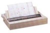
Paper Release Lever Paper Tension Roller Gear ~ PaperTensionRoller~\-T '::::s~ Transmission Gear -n .; ' :. .,, >" Platen Gear A / Paper Feed Motor Pinion Gear "..," Paper Feed Transmission Gear (i) Side View & o (ii) Top View (a) Gear Arrangement Paper Paper Tension Roller, > P u s h - Push Tractor Feeding Method 2-8 A paper tension unit is performed by driving the paper feed motor with the ...
Paper Release Lever Paper Tension Roller Gear ~ PaperTensionRoller~\-T '::::s~ Transmission Gear -n .; ' :. .,, >" Platen Gear A / Paper Feed Motor Pinion Gear "..," Paper Feed Transmission Gear (i) Side View & o (ii) Top View (a) Gear Arrangement Paper Paper Tension Roller, > P u s h - Push Tractor Feeding Method 2-8 A paper tension unit is performed by driving the paper feed motor with the ...

Technical Manual
Page 53
m, . ..r.c. Friction Feeding Method 2-9 ar I- REV.-A 2.2.5.2. Im,s, l --". - ' (O'--* * \P a p e r Feed ~otor / Paper Feed Transmission Gear pinion ~ear" q) Friction/Tractol Sensor (i) Side View *" (ii) Top View (a) Gear Arrangement Paper Tension Support Roller /" ..~-" Paper ~. As in the push tractor feed method, the paper tension unit is fed due to friction ...
m, . ..r.c. Friction Feeding Method 2-9 ar I- REV.-A 2.2.5.2. Im,s, l --". - ' (O'--* * \P a p e r Feed ~otor / Paper Feed Transmission Gear pinion ~ear" q) Friction/Tractol Sensor (i) Side View *" (ii) Top View (a) Gear Arrangement Paper Tension Support Roller /" ..~-" Paper ~. As in the push tractor feed method, the paper tension unit is fed due to friction ...

Technical Manual
Page 56
I II ~1 I I ILEI 1111 .1 I I I I I I REV.-A 2.3.1.2 Control Circuit Section Figure 2-9 shows the control circuit block diagram.
I II ~1 I I ILEI 1111 .1 I I I I I I REV.-A 2.3.1.2 Control Circuit Section Figure 2-9 shows the control circuit block diagram.

Technical Manual
Page 60
REV.-A
REV.-A

Technical Manual
Page 63
... into the negative terminal of comparator 1, and the outputs from the oscillator is also input to the positive terminals. i-rc- u- -it- -2 J - - -1 - - i-t - 1 1 i II I I PWM Comparator 1 I I I t - - - - +- 1%12 Osc 3 1% -1 J r C-i-rc- PWM Comparator 2 I I I II I L i Figure 2-16, NJM2355 Internal Circuit 2-19 ,, A sawtooth waveform from AMP 2 and AMP 3 in Figure 2-17. REV.-A 2.3.2.5 Pulse-Width Modulation (PWM) Circuit Figure...
... into the negative terminal of comparator 1, and the outputs from the oscillator is also input to the positive terminals. i-rc- u- -it- -2 J - - -1 - - i-t - 1 1 i II I I PWM Comparator 1 I I I t - - - - +- 1%12 Osc 3 1% -1 J r C-i-rc- PWM Comparator 2 I I I II I L i Figure 2-16, NJM2355 Internal Circuit 2-19 ,, A sawtooth waveform from AMP 2 and AMP 3 in Figure 2-17. REV.-A 2.3.2.5 Pulse-Width Modulation (PWM) Circuit Figure...

Technical Manual
Page 92
... ICA gradually increases due to R 13. q When the carriage motor stops, the motor drive pulses are fixed at the minus side) when the printer power is turned on, TR7 turns on , and coil current ICA flows from overheating. At this time, approximately 5V is supplied to drop the ... base of transistor Q5, and is absorbed by PWM control. As a result, the load on to VCOMAB by transistor Q5 to TR 1. K '7:F T 1 II t II - and TR 11 turns on VCOMAB is reduced and H-IC is effectively powered down, At this time, H-IC is powered down ; REV.-A Detailed Operation (Figure...
... ICA gradually increases due to R 13. q When the carriage motor stops, the motor drive pulses are fixed at the minus side) when the printer power is turned on, TR7 turns on , and coil current ICA flows from overheating. At this time, approximately 5V is supplied to drop the ... base of transistor Q5, and is absorbed by PWM control. As a result, the load on to VCOMAB by transistor Q5 to TR 1. K '7:F T 1 II t II - and TR 11 turns on VCOMAB is reduced and H-IC is effectively powered down, At this time, H-IC is powered down ; REV.-A Detailed Operation (Figure...

Technical Manual
Page 96
Figure 2-42. Detects HP Signal Reads and sets the phase change Point in the CPU. . . . Home Seek Phase States .i-"-- 2-52 REV.-A ( In HP Signal out ( Phase A 1 Phase B CR Motor Phase C [ I I I I 1 1 I II I I I I 1 1 1 I I 2 3 4il 2 I 3 --
Figure 2-42. Detects HP Signal Reads and sets the phase change Point in the CPU. . . . Home Seek Phase States .i-"-- 2-52 REV.-A ( In HP Signal out ( Phase A 1 Phase B CR Motor Phase C [ I I I I 1 1 I II I I I I 1 1 1 I I 2 3 4il 2 I 3 --

Technical Manual
Page 99
...counterclockwise, paper is operated by following three speed modes for paper feeding. Paper Feed Motor Speed Feed Speed 660 pps 720 Pp!ii 780 PPS Excitation System Description 2-2 Phase Continuous paper feed 2-2 Phase Cut sheet intermittent feed 2-2 Phase Cut sheet continuous feed .... The minimum line spacing value that the user can set is also controlled by the printer firmware. Table 2-13. The table below shows the phase excitation sequence. The printer supports the following operation shown in reverse. 2.3.5.3 Paper Feed Motor Software Control This section ...
...counterclockwise, paper is operated by following three speed modes for paper feeding. Paper Feed Motor Speed Feed Speed 660 pps 720 Pp!ii 780 PPS Excitation System Description 2-2 Phase Continuous paper feed 2-2 Phase Cut sheet intermittent feed 2-2 Phase Cut sheet continuous feed .... The minimum line spacing value that the user can set is also controlled by the printer firmware. Table 2-13. The table below shows the phase excitation sequence. The printer supports the following operation shown in reverse. 2.3.5.3 Paper Feed Motor Software Control This section ...

Technical Manual
Page 104
Figure 2-50 shows a block diagram of the E05A15HA gate array. v ' 1' ) ' -D u') ~. = --- ---J GP +5 Printhead r-1 I I II I '!I ' -:" ' x I-- --I ...4 1 Vp Figure 2-50. CPU(MPD7810HG) Y (4B) P?7 PDO PC6 ANO L AN2 GA(E05A 15HA) 1 (3A) Buffer C3987X9 ---.r, -r \ - -- The printhead drive pulse output from the CPU is ...
Figure 2-50 shows a block diagram of the E05A15HA gate array. v ' 1' ) ' -D u') ~. = --- ---J GP +5 Printhead r-1 I I II I '!I ' -:" ' x I-- --I ...4 1 Vp Figure 2-50. CPU(MPD7810HG) Y (4B) P?7 PDO PC6 ANO L AN2 GA(E05A 15HA) 1 (3A) Buffer C3987X9 ---.r, -r \ - -- The printhead drive pulse output from the CPU is ...

Technical Manual
Page 106
... located in the gate array (E05AI 5HA). Halfdot Protection Circuit Block Diagram 2-62 I I I 1 1 I I I I Buffer N v I +- ~J Holf dot Protect Ion Circuit 9uffer It A ~Dd III To Prlntheod Driver I1IItI11 iI i- It ignores any drive pulses received after the dot wires of the printhead (see Figure 2-3) have been driven for the maximum allowable drive time, to...
... located in the gate array (E05AI 5HA). Halfdot Protection Circuit Block Diagram 2-62 I I I 1 1 I I I I Buffer N v I +- ~J Holf dot Protect Ion Circuit 9uffer It A ~Dd III To Prlntheod Driver I1IItI11 iI i- It ignores any drive pulses received after the dot wires of the printhead (see Figure 2-3) have been driven for the maximum allowable drive time, to...

Technical Manual
Page 111
...Plunger Positioning 4. . -22 Figure 4-30. Ribbon Cartridge and Platen Knob Removal 4-3 Figure 4-3. Transport Locking Brackets Installation 4-3 Figure 4-4. Printer Disassemlby Procedures 4-5 Figure 4-7. PEGX Board Removal 4. -1o Figure 4-13. FPC Removal 4. .-15 Figure 4-20. Timing Belt Insertion 4....Tractor Unit Removal 4. -8 Figure 4-10. Printer Mechanism's Component Relationship ......... 4-12 Figure 4-15. Parts of the FX-850/1050 4. -2 Figure 4-2. Plunger Removal 4. -.22 Figure 4-29. Wire Clamp Positions 4-25 4-ii Platen Cover Removal 4. -23 Figure 4-31...
...Plunger Positioning 4. . -22 Figure 4-30. Ribbon Cartridge and Platen Knob Removal 4-3 Figure 4-3. Transport Locking Brackets Installation 4-3 Figure 4-4. Printer Disassemlby Procedures 4-5 Figure 4-7. PEGX Board Removal 4. -1o Figure 4-13. FPC Removal 4. .-15 Figure 4-20. Timing Belt Insertion 4....Tractor Unit Removal 4. -8 Figure 4-10. Printer Mechanism's Component Relationship ......... 4-12 Figure 4-15. Parts of the FX-850/1050 4. -2 Figure 4-2. Plunger Removal 4. -.22 Figure 4-29. Wire Clamp Positions 4-25 4-ii Platen Cover Removal 4. -23 Figure 4-31...

Technical Manual
Page 125
... FPC Removal A I section 402.5,8 Friction/Troctor Sensor Removal 1 n t Section 4.2, 5,7 I Section 4,2,5.4 I Figure 4-14. Printer Mechanism's Component Relationship 4-12 Refer to Figures A-20 through A-25 in the Appendix during assembly. Section 4.2.5.11 1 Pqwr Releose Lever...Feed Roller I I Removal I 1 Section ~ I Ribbon D1river -nd sensor I I Removal II Removal I Section 4,2.5.5 1 =?=J -.,-. REV.-A 4.2.5 Printer Mechanism Disassembly F-"., .; This section describes the procedures for reference during assembly. i . . . . . . Figure 4-...
... FPC Removal A I section 402.5,8 Friction/Troctor Sensor Removal 1 n t Section 4.2, 5,7 I Section 4,2,5.4 I Figure 4-14. Printer Mechanism's Component Relationship 4-12 Refer to Figures A-20 through A-25 in the Appendix during assembly. Section 4.2.5.11 1 Pqwr Releose Lever...Feed Roller I I Removal I 1 Section ~ I Ribbon D1river -nd sensor I I Removal II Removal I Section 4,2.5.5 1 =?=J -.,-. REV.-A 4.2.5 Printer Mechanism Disassembly F-"., .; This section describes the procedures for reference during assembly. i . . . . . . Figure 4-...