Service Manual
Page 4
... chapters are intended for reference: • Connector pin assignments • Electric circuit boards components layout • Exploded diagram • Electrical circuit boards schematics The instructions and procedures included herein are organized as follows: CHAPTER 1. OPERATING PRINCIPLES... Describes the theory of electrical and mechanical operations of the product. ADJUSTMENTS Provides Epson-approved methods for servicing the product. CHAPTER 4. CHAPTER 6. PREFACE This manual describes basic functions, theory of electrical...
... chapters are intended for reference: • Connector pin assignments • Electric circuit boards components layout • Exploded diagram • Electrical circuit boards schematics The instructions and procedures included herein are organized as follows: CHAPTER 1. OPERATING PRINCIPLES... Describes the theory of electrical and mechanical operations of the product. ADJUSTMENTS Provides Epson-approved methods for servicing the product. CHAPTER 4. CHAPTER 6. PREFACE This manual describes basic functions, theory of electrical...
Service Manual
Page 8
ADJUSTMENT 5.1 ADJUSTMENT OVERVIEW 5-1 5.1.1 Required Adjustment 5-1 5.1.2 Adjustment Tools 5-1 5.2 ADJUSTING AND RESETTING THE PRINTER 5-2 5.2.1 Platen Gap Adjustment 5-2 5.2.2 Factory Setting 5-4 5.2.3 Bi-D Adjustment 5-6 MAINTENANCE 6.1 PREVENTIVE MAINTENANCE 6-1 6.2 LUBRICATION 6-2 APPENDIX 7.1 CONNECTOR SUMMARY 7-1 7.2 COMPONENT LAYOUT 7-6 7.3 DIMENSIONS AND WEIGHT 7-9 7.4 EXPLODED DIAGRAM 7-11 7.5 CIRCUIT DIAGRAM 7-16
ADJUSTMENT 5.1 ADJUSTMENT OVERVIEW 5-1 5.1.1 Required Adjustment 5-1 5.1.2 Adjustment Tools 5-1 5.2 ADJUSTING AND RESETTING THE PRINTER 5-2 5.2.1 Platen Gap Adjustment 5-2 5.2.2 Factory Setting 5-4 5.2.3 Bi-D Adjustment 5-6 MAINTENANCE 6.1 PREVENTIVE MAINTENANCE 6-1 6.2 LUBRICATION 6-2 APPENDIX 7.1 CONNECTOR SUMMARY 7-1 7.2 COMPONENT LAYOUT 7-6 7.3 DIMENSIONS AND WEIGHT 7-9 7.4 EXPLODED DIAGRAM 7-11 7.5 CIRCUIT DIAGRAM 7-16
Service Manual
Page 27
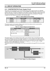
... on the board. R C C S w itc h in the following table: Table 2-2. 2.3 CIRCUIT OPERATION FX-1180/FX-880 Service Manual Chapter 2 Operating Principles 2.3.1 C229PSB/PSE/PSH Power Supply Circuit This printer can be powered by the regulator IC. The AC voltage is first input to the line filter circuit... for a difference in e F ilte r Z C - Power Supply Circuit Block Diagram Rev....
... on the board. R C C S w itc h in the following table: Table 2-2. 2.3 CIRCUIT OPERATION FX-1180/FX-880 Service Manual Chapter 2 Operating Principles 2.3.1 C229PSB/PSE/PSH Power Supply Circuit This printer can be powered by the regulator IC. The AC voltage is first input to the line filter circuit... for a difference in e F ilte r Z C - Power Supply Circuit Block Diagram Rev....
Service Manual
Page 28
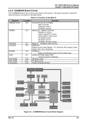
...IC2 IC1 IC4 IC5 IC7 IC8 IC11 IC12 Function 16 bit CPU runs at 14.47MHz - Main controller - CR Motor Control Gate array : System Controller - FX-1180/FX-880 Service Manual Chapter 2 Operating Principles 2.3.2 C229MAIN Board Circuit The C229MAIN board is to r Figure 2-5 . Printhead Control - PF Motor Control - CR ...in the table below: Table 2-3. This board consists of several IC chips and drivers, as shown in th e a d T h e r m is the control circuit board of this printer. C229MAIN Board Circuit Block Diagram Rev. Parallel I /F control - Panel Switch, LED control -
...IC2 IC1 IC4 IC5 IC7 IC8 IC11 IC12 Function 16 bit CPU runs at 14.47MHz - Main controller - CR Motor Control Gate array : System Controller - FX-1180/FX-880 Service Manual Chapter 2 Operating Principles 2.3.2 C229MAIN Board Circuit The C229MAIN board is to r Figure 2-5 . Printhead Control - PF Motor Control - CR ...in the table below: Table 2-3. This board consists of several IC chips and drivers, as shown in th e a d T h e r m is the control circuit board of this printer. C229MAIN Board Circuit Block Diagram Rev. Parallel I /F control - Panel Switch, LED control -

Service Manual
Page 53
FX-1180/FX-880 Service Manual Chapter 4 DISASSEMBLY AND ASSEMBLY 4.2 DISASSEMBLY AND ASSEMBLY This section provides the disassembly procedures. M a in C o m p o r n e n ts D is shown in the flowchart below. B 4-4 Disassembly Flowchart Rev. The exploded diagrams are also provided in R e m o v a l R ib b o n D r iv e A s s e m b ly R e m o v a l R e a r P a p e r G u id e A s s e m b ly R e m o v a l P G D e te c to r R em oval R e le a s e D e te c to r R em oval F ro n t P E D e te c to...
FX-1180/FX-880 Service Manual Chapter 4 DISASSEMBLY AND ASSEMBLY 4.2 DISASSEMBLY AND ASSEMBLY This section provides the disassembly procedures. M a in C o m p o r n e n ts D is shown in the flowchart below. B 4-4 Disassembly Flowchart Rev. The exploded diagrams are also provided in R e m o v a l R ib b o n D r iv e A s s e m b ly R e m o v a l R e a r P a p e r G u id e A s s e m b ly R e m o v a l P G D e te c to r R em oval R e le a s e D e te c to r R em oval F ro n t P E D e te c to...

Service Manual
Page 96
B 7-11 7.4 EXPLODED DIAGRAM See the following pages for the exploded diagrams below: • Exploded Diagram for FX-1180 (1) • Exploded Diagram for FX-1180 (2) • Exploded Diagram for FX-880 (1) • Exploded Diagram for FX-880 (2) FX-1180/FX-880 Service Manual Appendix Rev.
B 7-11 7.4 EXPLODED DIAGRAM See the following pages for the exploded diagrams below: • Exploded Diagram for FX-1180 (1) • Exploded Diagram for FX-1180 (2) • Exploded Diagram for FX-880 (1) • Exploded Diagram for FX-880 (2) FX-1180/FX-880 Service Manual Appendix Rev.
Service Manual
Page 101
B 7-16 7.5 CIRCUIT DIAGRAM See the following pages for the circuit diagrams below: • C229MAIN Circuit Diagram • C229PSB Circuit Diagram • C229PSE Circuit Diagram • C229PSH Circuit Diagram • C229PNL Circuit Diagram FX-1180/FX-880 Service Manual Appendix Rev.
B 7-16 7.5 CIRCUIT DIAGRAM See the following pages for the circuit diagrams below: • C229MAIN Circuit Diagram • C229PSB Circuit Diagram • C229PSE Circuit Diagram • C229PSH Circuit Diagram • C229PNL Circuit Diagram FX-1180/FX-880 Service Manual Appendix Rev.