User Manual
Page 10
... daily use of the major parts identified. This information is necessary for the day-to the illustrations when you are illustrations of the printer with all of the printer. Chapter 7 contains troubleshooting information, including a list of your printing, maintaining the printer, using the printer. Chapter 1 shows you '...the instructions in this manual are setting up and operating the DFX-5000 printer. Inside the back cover of this chapter first. Chapters 2 and 3 give you will need for setting up and operating the printer. You can unfold the cover and refer to -day ...
... daily use of the major parts identified. This information is necessary for the day-to the illustrations when you are illustrations of the printer with all of the printer. Chapter 7 contains troubleshooting information, including a list of your printing, maintaining the printer, using the printer. Chapter 1 shows you '...the instructions in this manual are setting up and operating the DFX-5000 printer. Inside the back cover of this chapter first. Chapters 2 and 3 give you will need for setting up and operating the printer. You can unfold the cover and refer to -day ...

User Manual
Page 33
...series of characters. To run in either draft,, high-speed draft, or near letter quality (NLQ) mode. A list of your printer's settings is part of the printer's DIP switches and the characters in the printer's memory. If the test results are satisfactory and you press the ON LINE button. After printing starts, release ... until the paper runs out or until you wish to stop the test, press the ON LINE button to take the printer off line, and then turn on the printer. Running the self test The self test prints out the settings of a typical self test printout in high-speed draft....
...series of characters. To run in either draft,, high-speed draft, or near letter quality (NLQ) mode. A list of your printer's settings is part of the printer's DIP switches and the characters in the printer's memory. If the test results are satisfactory and you press the ON LINE button. After printing starts, release ... until the paper runs out or until you wish to stop the test, press the ON LINE button to take the printer off line, and then turn on the printer. Running the self test The self test prints out the settings of a typical self test printout in high-speed draft....

User Manual
Page 109
l Proportional overrides 10 cpi, 12 cpi, and condensed. If other combinations are not part of the listed features that you try to use Master Select to set emphasized double-strike only, the character width is selected. Print quality and font are used, ... set 12 cpi, and you do not set separately using the ESC x and ESC k commands. l Only underlining can be set . Getting the Most from Your Printer 4-13 l Double-strike is ignored when combined with high-speed draft without slowing the print speed. Consider these things when you use the Master Select...
l Proportional overrides 10 cpi, 12 cpi, and condensed. If other combinations are not part of the listed features that you try to use Master Select to set emphasized double-strike only, the character width is selected. Print quality and font are used, ... set 12 cpi, and you do not set separately using the ESC x and ESC k commands. l Only underlining can be set . Getting the Most from Your Printer 4-13 l Double-strike is ignored when combined with high-speed draft without slowing the print speed. Consider these things when you use the Master Select...

User Manual
Page 149
...Printer operation Data control Vertical motion Horizontal motion Overall printing style Print size and character width Print enhancement Word processing Character sets User-defined characters Graphics Each command has a format section and a comment section. The Quick Reference card at the end of the book also contains a list... the one most suited to full explanations of this chapter lists and describes each is described. Note: Some application programs... lists and describes all commands in numerical order and gives the page number where each command separately; The first part of...
...Printer operation Data control Vertical motion Horizontal motion Overall printing style Print size and character width Print enhancement Word processing Character sets User-defined characters Graphics Each command has a format section and a comment section. The Quick Reference card at the end of the book also contains a list... the one most suited to full explanations of this chapter lists and describes each is described. Note: Some application programs... lists and describes all commands in numerical order and gives the page number where each command separately; The first part of...

Service Manual
Page 8
... Pin Assignments 1-15 Table 1-8. Pin Configuration 1-3 Figure 1-3. Sprocket Holes 1-7 Figure 1-11. Printable Area, Overlapping Multi-part Forms 1-8 Figure 1-14. Dotted Paste Positions 1-9 Figure 1-15. Control Panel 1-17 Figure 1-24. Main Components 1-26 Figure 1-27. Options and Consumables...1-25 Table 1-17. List of the DFX-5000 1-1 Figure 1-2. Acceptable Environmental Conditions 1-12 Table 1-6. Selecting the Paper Memory Area 1-20 Table 1-10. Printable Area for Labels 1-11 Figure 1-21. Stapled Area 2 1-9 Figure 1-17. M-3C11 Printer Mechanism 1-27 Figure 1-28...
... Pin Assignments 1-15 Table 1-8. Pin Configuration 1-3 Figure 1-3. Sprocket Holes 1-7 Figure 1-11. Printable Area, Overlapping Multi-part Forms 1-8 Figure 1-14. Dotted Paste Positions 1-9 Figure 1-15. Control Panel 1-17 Figure 1-24. Main Components 1-26 Figure 1-27. Options and Consumables...1-25 Table 1-17. List of the DFX-5000 1-1 Figure 1-2. Acceptable Environmental Conditions 1-12 Table 1-6. Selecting the Paper Memory Area 1-20 Table 1-10. Printable Area for Labels 1-11 Figure 1-21. Stapled Area 2 1-9 Figure 1-17. M-3C11 Printer Mechanism 1-27 Figure 1-28...

Service Manual
Page 68
...total number of next pulse is the largest, and Dutytil represents the minimum duty data for SP2.) The printer saves the values fir each section number. The number of the items listed above and uses it uses Deceleration driving mode 1. (Refer to the stopping point. 3. Figure 2-26 ...the eight most recent sections. 3. The time between the last 40 encoder pukes and the stopping point. 2. The printer uses Deceleration driving mode 2, based on part of the time and off part of carriage movements and saves this number. 2. SpeedO) takes effect. SP3 - This control method is 72.5 ms....
...total number of next pulse is the largest, and Dutytil represents the minimum duty data for SP2.) The printer saves the values fir each section number. The number of the items listed above and uses it uses Deceleration driving mode 1. (Refer to the stopping point. 3. Figure 2-26 ...the eight most recent sections. 3. The time between the last 40 encoder pukes and the stopping point. 2. The printer uses Deceleration driving mode 2, based on part of the time and off part of carriage movements and saves this number. 2. SpeedO) takes effect. SP3 - This control method is 72.5 ms....

Service Manual
Page 75
Packing the DFX-5000 3-2 Figure3-3. Removingthe FPC Cover and theConnectors 3-7 Figure ...-7. Replacing the ROM 3-9 Figure3-10. Removing the Interlock Switch Assembly 3-21 Figure 3-28. Removing the Left Part of Figures Figure 3-1. Removing the Pull Tractor Sensor 3-35 Figure 3-47. Dial Gauges 3-4 Figure3-4. Removing the...Assembly 3-18 Figure 3-23. Removing the Tractor Select Lever2 3-24 Figure 3-33. Lifting the Printer Mechanism 3-23 Figure 3-30. List of Lower Paper Guide 3-34 Figure 3-45. Removing the lnterfaceCover 3-15 Figure3-19. Removing...
Packing the DFX-5000 3-2 Figure3-3. Removingthe FPC Cover and theConnectors 3-7 Figure ...-7. Replacing the ROM 3-9 Figure3-10. Removing the Interlock Switch Assembly 3-21 Figure 3-28. Removing the Left Part of Figures Figure 3-1. Removing the Pull Tractor Sensor 3-35 Figure 3-47. Dial Gauges 3-4 Figure3-4. Removing the...Assembly 3-18 Figure 3-23. Removing the Tractor Select Lever2 3-24 Figure 3-33. Lifting the Printer Mechanism 3-23 Figure 3-30. List of Lower Paper Guide 3-34 Figure 3-45. Removing the lnterfaceCover 3-15 Figure3-19. Removing...

Service Manual
Page 76
... Motor 3-41 Figure 3-56. Removing the CR Sensor 3-42 Figure 3-57. Removing the Timing Belt Holder 3-41 Figure 3-55. Abbreviations for Small Parts 3-5 Table 3-3. Removing the Right Side Frame 3-44 List of Tables Table 3-1. Tools 3-3 Table 3-2. Removing the Front Carriage Guide Shaft 3-43 Figure 3-59. Screw Names and Illustrations 3-6 Removing the Belt...
... Motor 3-41 Figure 3-56. Removing the CR Sensor 3-42 Figure 3-57. Removing the Timing Belt Holder 3-41 Figure 3-55. Abbreviations for Small Parts 3-5 Table 3-3. Removing the Right Side Frame 3-44 List of Tables Table 3-1. Tools 3-3 Table 3-2. Removing the Front Carriage Guide Shaft 3-43 Figure 3-59. Screw Names and Illustrations 3-6 Removing the Belt...

Service Manual
Page 137
Error Codes 5-1 Table 5-2. Cl 17 PSB/PSE Board Assembly Main Parts List 5-13 Table 5-5. Printhead Coil Resistance 5-3 List of Figures Figure 5-1. Printer Mechanism Repair 5-24 Motor, Fan, Plunger, and Printhead Coil Resistance 5-3 Table 5-3. C117 PSBIPSE Board ... REPAIR BY UNIT REPLACEMENT 5-4 5.3 REPAIR OF THE POWER SUPPLY CIRCUIT 5-13 5.4 REPAIR OF THE C117 MAIN BOARD ASSEMBLY 5-17 5.5 PRINTER MECHANISM 5-24 List of Tables Table 5-1. Symptoms and Reference Pages 5-4 Table 5-4. Bypassing the Cover Open Sensor 5-2 Figure 5-3. C117 MAIN Board Assembly Component ...
Error Codes 5-1 Table 5-2. Cl 17 PSB/PSE Board Assembly Main Parts List 5-13 Table 5-5. Printhead Coil Resistance 5-3 List of Figures Figure 5-1. Printer Mechanism Repair 5-24 Motor, Fan, Plunger, and Printhead Coil Resistance 5-3 Table 5-3. C117 PSBIPSE Board ... REPAIR BY UNIT REPLACEMENT 5-4 5.3 REPAIR OF THE POWER SUPPLY CIRCUIT 5-13 5.4 REPAIR OF THE C117 MAIN BOARD ASSEMBLY 5-17 5.5 PRINTER MECHANISM 5-24 List of Tables Table 5-1. Symptoms and Reference Pages 5-4 Table 5-4. Bypassing the Cover Open Sensor 5-2 Figure 5-3. C117 MAIN Board Assembly Component ...
Service Manual
Page 150
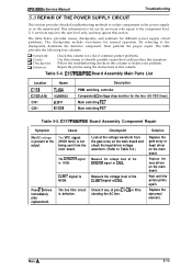
...unit level only, and may ignore this section. C117 PSB/PSE Board Assembly Main Parts List Location IC151 IC152 (A/B) Q101 Q201 Name TL494 NJM2903 K1 531 K1531 Description PWM switching... of common printer problems. Use this column to identify possible causes that could produce this column. Wait until the printer prints again. A 5-13 Repair the printer using the ...at the voltage waveform from the main board. This information is shorting the AC line. DFX-5000+ Service Manual Troubleshooting 5.3 REPAIR OF THE POWER SUPPLY CIRCUIT This section provides detailed troubleshooting...
...unit level only, and may ignore this section. C117 PSB/PSE Board Assembly Main Parts List Location IC151 IC152 (A/B) Q101 Q201 Name TL494 NJM2903 K1 531 K1531 Description PWM switching... of common printer problems. Use this column to identify possible causes that could produce this column. Wait until the printer prints again. A 5-13 Repair the printer using the ...at the voltage waveform from the main board. This information is shorting the AC line. DFX-5000+ Service Manual Troubleshooting 5.3 REPAIR OF THE POWER SUPPLY CIRCUIT This section provides detailed troubleshooting...

Service Manual
Page 166
... found to the points indicated in Figures 6-2,6-3, and 6-4. EPSON recommends Neji Lock #2 (G) adhesive be applied to comply with needs of the printer. After cleaning the printer, check that the printer be lubricated are disassembled or replaced. DFX-5000+ Service Manual Maintenance and Lubrication 6.1 PREVENTIVE MAINTENANCE To keep the printer in good condition, regularly clean the case exterior...
... found to the points indicated in Figures 6-2,6-3, and 6-4. EPSON recommends Neji Lock #2 (G) adhesive be applied to comply with needs of the printer. After cleaning the printer, check that the printer be lubricated are disassembled or replaced. DFX-5000+ Service Manual Maintenance and Lubrication 6.1 PREVENTIVE MAINTENANCE To keep the printer in good condition, regularly clean the case exterior...


