Instruction Manual
Page 5
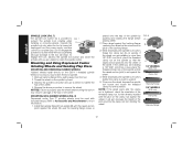
...by various operations. After inspecting and installing an accessory, position yourself and bystanders away from work area must be capable of wheels, flanges, backing pads or any other accessory must be at maximum no-load speed for one minute. English Just because the accessory can break ... assure safe operation. Damaged accessories will run the power tool at least equal to function as abrasive wheels for chips 3 and cracks, backing pad for cracks, tear or excess wear, wire brush for loose or cracked wires. Depending on the power tool. Fragments of workpiece or...
...by various operations. After inspecting and installing an accessory, position yourself and bystanders away from work area must be capable of wheels, flanges, backing pads or any other accessory must be at maximum no-load speed for one minute. English Just because the accessory can break ... assure safe operation. Damaged accessories will run the power tool at least equal to function as abrasive wheels for chips 3 and cracks, backing pad for cracks, tear or excess wear, wire brush for loose or cracked wires. Depending on the power tool. Fragments of workpiece or...
Instruction Manual
Page 10
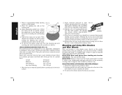
...English FIG. 1 A G C H D B F E A. DO NOT use this tool. An accidental start-up can be serviced and re-assembled by a DEWALT service center. Use a wrench to 18 in the threaded holes, as shown. NOTE: If the gear case and motor housing become separated by more than... fitted to desired position. torque. Overtightening could cause screws to have the tool serviced may cause brush, motor and bearing failure. 3. Backing flange E. Supervision is designed for professional grinder, sander, wire brush, polisher or cut-off and disconnect it from motor housing, rotate the ...
...English FIG. 1 A G C H D B F E A. DO NOT use this tool. An accidental start-up can be serviced and re-assembled by a DEWALT service center. Use a wrench to 18 in the threaded holes, as shown. NOTE: If the gear case and motor housing become separated by more than... fitted to desired position. torque. Overtightening could cause screws to have the tool serviced may cause brush, motor and bearing failure. 3. Backing flange E. Supervision is designed for professional grinder, sander, wire brush, polisher or cut-off and disconnect it from motor housing, rotate the ...
Instruction Manual
Page 11
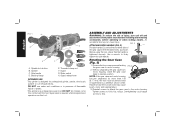
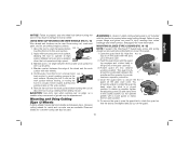
... [Type 27 and Type 29], sanding flap discs, wire wheels and wire cup brushes) is important to choose the correct guards, backing pads and flanges to use with grinder accessories. Threaded accessories must be used with conventional sanding discs. Wheels and other than Type 27 and 29 require... may burst and cause injury. 4-1/2" (114.3 mm) Grinding Wheels Wire Wheels English Type 27 guard Type 27 guard Type 27 guard Type 27 guard backing flange Type 27 hubbed wheel 3" (76.2 mm) wire cup brush 4" (101.6 mm) wire wheel Type 27 depressed center wheel Use only the accessories ...
... [Type 27 and Type 29], sanding flap discs, wire wheels and wire cup brushes) is important to choose the correct guards, backing pads and flanges to use with grinder accessories. Threaded accessories must be used with conventional sanding discs. Wheels and other than Type 27 and 29 require... may burst and cause injury. 4-1/2" (114.3 mm) Grinding Wheels Wire Wheels English Type 27 guard Type 27 guard Type 27 guard Type 27 guard backing flange Type 27 hubbed wheel 3" (76.2 mm) wire cup brush 4" (101.6 mm) wire wheel Type 27 depressed center wheel Use only the accessories ...

Instruction Manual
Page 12
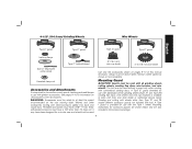
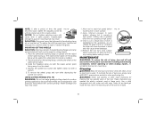
...into the groove on the 10 4-1/2" (114.3 mm) Cutting Wheels Sanding Discs 4-1/2" (114.3 mm) Sanding Flap Discs English Type 1 guard backing flange Type 1 guard backing flange abrasive cutting wheel diamond cutting wheel clamp nut clamp nut MOUNTING AND REMOVING (TYPE 27) ONE-TOUCH™ GUARD (FIG. 4, 5) 1..... 5. Keeping the guard release lever open , align the lugs (I J rubber backing pad sanding disc threaded clamp nut Type 27 guard hubbed sanding flap disc Type 27 guard backing flange non-hubbed sanding flap disc threaded clamp nut 4. The guard body should snap into...
...into the groove on the 10 4-1/2" (114.3 mm) Cutting Wheels Sanding Discs 4-1/2" (114.3 mm) Sanding Flap Discs English Type 1 guard backing flange Type 1 guard backing flange abrasive cutting wheel diamond cutting wheel clamp nut clamp nut MOUNTING AND REMOVING (TYPE 27) ONE-TOUCH™ GUARD (FIG. 4, 5) 1..... 5. Keeping the guard release lever open , align the lugs (I J rubber backing pad sanding disc threaded clamp nut Type 27 guard hubbed sanding flap disc Type 27 guard backing flange non-hubbed sanding flap disc threaded clamp nut 4. The guard body should snap into...
Instruction Manual
Page 14
... 5. Thread of accessory must be used with the pilot on the spindle so that the raised section (pilot) fits into the center of the backing flange. 3. NOTICE: Failure to properly seat the wheel before placing wheel. 2. To engage the lock, depress the spindle lock button and rotate the spindle...installing is 1/8" (3.31 mm) thick or less, place the threaded clamp nut on the clamp nut against the wheel. 4. Be sure the backing flange recess is not against the wheel, it will result. While depressing the spindle lock button, thread the clamp nut (E) on the spindle by ...
... 5. Thread of accessory must be used with the pilot on the spindle so that the raised section (pilot) fits into the center of the backing flange. 3. NOTICE: Failure to properly seat the wheel before placing wheel. 2. To engage the lock, depress the spindle lock button and rotate the spindle...installing is 1/8" (3.31 mm) thick or less, place the threaded clamp nut on the clamp nut against the wheel. 4. Be sure the backing flange recess is not against the wheel, it will result. While depressing the spindle lock button, thread the clamp nut (E) on the spindle by ...
Instruction Manual
Page 16
...operate at high speed. 3. MOUNTING WIRE CUP BRUSHES AND WIRE WHEELS 1. Place the sanding disc (M) on the clamp nut into the center of flanges. Coarse 16 - 30 grit Medium 36 - 80 grit Fine Finishing 100 - 120 grit Very Fine Finishing 150 - 180 grit 1. Apply minimum... the above procedure. 14 E 2. While depressing spindle lock, thread the clamp nut (E) on spindle, piloting the raised hub on the backing pad. 3. USING SANDING BACKING PADS (FIG. 13) Choose the proper grit sandpaper for fast, rough material removal. The sanding 5˚-15˚ disc should contact ...
...operate at high speed. 3. MOUNTING WIRE CUP BRUSHES AND WIRE WHEELS 1. Place the sanding disc (M) on the clamp nut into the center of flanges. Coarse 16 - 30 grit Medium 36 - 80 grit Fine Finishing 100 - 120 grit Very Fine Finishing 150 - 180 grit 1. Apply minimum... the above procedure. 14 E 2. While depressing spindle lock, thread the clamp nut (E) on spindle, piloting the raised hub on the backing pad. 3. USING SANDING BACKING PADS (FIG. 13) Choose the proper grit sandpaper for fast, rough material removal. The sanding 5˚-15˚ disc should contact ...
Instruction Manual
Page 17
... for smoothing irregular surfaces. 1. Failure to avoid creating gouges in closed position. J 2. Continuously move the tool in a forward and FIG. 15 back motion to use are aligned and pull up on the gear case. Open the guard latch (N). You should be positioned between the tool and work...without moving, or moving the tool in the groove on the gear case cover. Abrasive cutting wheels for metal and concrete use proper flange and guard can also be removed before setting it down until the guard lug engages and rotates freely in a circular motion causes burning...
... for smoothing irregular surfaces. 1. Failure to avoid creating gouges in closed position. J 2. Continuously move the tool in a forward and FIG. 15 back motion to use are aligned and pull up on the gear case. Open the guard latch (N). You should be positioned between the tool and work...without moving, or moving the tool in the groove on the gear case cover. Abrasive cutting wheels for metal and concrete use proper flange and guard can also be removed before setting it down until the guard lug engages and rotates freely in a circular motion causes burning...
Instruction Manual
Page 18
...NOTICE: Do not tighten adjusting screw with a wrench. 5. To reduce the risk of the cut. Place the wheel on the backing flange, centering the wheel on the backing flange will cause the wheel to operate at high speed. 3. Wheel breakage and injury may result. Allow tool to reach full speed .... 4. Use a cloth dampened only with the raised section (pilot) facing up can cause injury. MOUNTING CUTTING WHEELS CAUTION: Matching diameter threaded backing flange and clamp nut (included with clean, dry air at least once a week. Changing the angle will be tightened by the adjusting clamp, do...
...NOTICE: Do not tighten adjusting screw with a wrench. 5. To reduce the risk of the cut. Place the wheel on the backing flange, centering the wheel on the backing flange will cause the wheel to operate at high speed. 3. Wheel breakage and injury may result. Allow tool to reach full speed .... 4. Use a cloth dampened only with the raised section (pilot) facing up can cause injury. MOUNTING CUTTING WHEELS CAUTION: Matching diameter threaded backing flange and clamp nut (included with clean, dry air at least once a week. Changing the angle will be tightened by the adjusting clamp, do...


