Instruction Manual
Page 5
... tool "live" and could give the operator an electrical shock. e) The arbor size of wheels, flanges, backing pads or any other accessory must be adequately guarded or controlled. Before each use face shield, safety goggles or safety glasses. Fragments of workpiece or of a broken accessory may cause loss of the power...
... tool "live" and could give the operator an electrical shock. e) The arbor size of wheels, flanges, backing pads or any other accessory must be adequately guarded or controlled. Before each use face shield, safety goggles or safety glasses. Fragments of workpiece or of a broken accessory may cause loss of the power...

Instruction Manual
Page 7
...placed under their own weight. Abrasive cut-off wheel or apply excessive pressure. b) Do not position your power tool and the specific guard designed for larger power tool is exposed towards the operator. Investigate and take corrective action to these wheels may cut gas or water ... which the power tool was not designed cannot be used only for the higher speed of wheel pinching and kickback. b) The guard must be adequately guarded and are of wheel breakage. Flanges for cut and the possibility of wheel is not suitable for recommended applications. e) Do not...
...placed under their own weight. Abrasive cut-off wheel or apply excessive pressure. b) Do not position your power tool and the specific guard designed for larger power tool is exposed towards the operator. Investigate and take corrective action to these wheels may cut gas or water ... which the power tool was not designed cannot be used only for the higher speed of wheel pinching and kickback. b) The guard must be adequately guarded and are of wheel breakage. Flanges for cut and the possibility of wheel is not suitable for recommended applications. e) Do not...
Instruction Manual
Page 8
... permanent injury to fingers, hands, and arms. Use gloves to provide extra cushion, take frequent rest periods, and limit daily time of use of a guard is not recommended and may expand in doubt, use depending on the workpiece. The smaller the gauge number of the wire, the greater the capacity... and nameplate ampere rating. If in diameter due to work by the brush even during coast-down of the wire wheel or brush with the guard. Tuck away or trim any loose attachment strings. Vibration caused by applying excessive load to the brush. When using more capacity than its attachment...
... permanent injury to fingers, hands, and arms. Use gloves to provide extra cushion, take frequent rest periods, and limit daily time of use of a guard is not recommended and may expand in doubt, use depending on the workpiece. The smaller the gauge number of the wire, the greater the capacity... and nameplate ampere rating. If in diameter due to work by the brush even during coast-down of the wire wheel or brush with the guard. Tuck away or trim any loose attachment strings. Vibration caused by applying excessive load to the brush. When using more capacity than its attachment...
Instruction Manual
Page 10
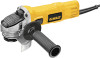
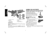
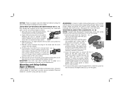
Side handle D. Guard release lever INTENDED USE This grinder is required when inexperienced operators use under wet conditions or in presence of flammable liquids or gases. Supervision is ... case to 18 in the threaded holes, as shown. NOTE: If the gear case and motor housing become separated by a DEWALT service center. Tighten screws to motor housing. 2. Spindle C. Backing flange E. Guard G. DO NOT let children come into contact with the tool. ATTACHING SIDE HANDLE (FIG. 2) FIG. 2 C The side handle (C) can cause...
Side handle D. Guard release lever INTENDED USE This grinder is required when inexperienced operators use under wet conditions or in presence of flammable liquids or gases. Supervision is ... case to 18 in the threaded holes, as shown. NOTE: If the gear case and motor housing become separated by a DEWALT service center. Tighten screws to motor housing. 2. Spindle C. Backing flange E. Guard G. DO NOT let children come into contact with the tool. ATTACHING SIDE HANDLE (FIG. 2) FIG. 2 C The side handle (C) can cause...
Instruction Manual
Page 11
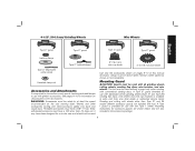
... center grinding wheels [Type 27 and Type 29], sanding flap discs, wire wheels and wire cup brushes) is important to choose the correct guards, backing pads and flanges to use with all grinding wheels, cutting wheels, sanding flap discs, wire brushes, and wire wheels. Wheels and ... shown below and are also included in the accessory package. 9 4-1/2" (114.3 mm) Grinding Wheels Wire Wheels English Type 27 guard Type 27 guard Type 27 guard Type 27 guard backing flange Type 27 hubbed wheel 3" (76.2 mm) wire cup brush 4" (101.6 mm) wire wheel Type 27 depressed center wheel Use...
... center grinding wheels [Type 27 and Type 29], sanding flap discs, wire wheels and wire cup brushes) is important to choose the correct guards, backing pads and flanges to use with all grinding wheels, cutting wheels, sanding flap discs, wire brushes, and wire wheels. Wheels and ... shown below and are also included in the accessory package. 9 4-1/2" (114.3 mm) Grinding Wheels Wire Wheels English Type 27 guard Type 27 guard Type 27 guard Type 27 guard backing flange Type 27 hubbed wheel 3" (76.2 mm) wire cup brush 4" (101.6 mm) wire wheel Type 27 depressed center wheel Use...

Instruction Manual
Page 12
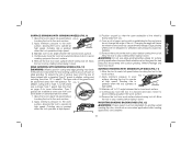
...operator to provide maximum operator protection. 5. While holding the guard release lever open , push the guard down until engage the lugs and rotate them into the groove on the gear case hub. Release the guard release lever. FIG. 4 I ) on the guard with the slots on the 10 With the spindle facing the... operator, rotate FIG. 5 the guard clockwise into one of the alignment holes (K) on the gear case (J). 3. Keeping ...
...operator to provide maximum operator protection. 5. While holding the guard release lever open , push the guard down until engage the lugs and rotate them into the groove on the gear case hub. Release the guard release lever. FIG. 4 I ) on the guard with the slots on the 10 With the spindle facing the... operator, rotate FIG. 5 the guard clockwise into one of the alignment holes (K) on the gear case (J). 3. Keeping ...
Instruction Manual
Page 13
... supply, be rated for a circular saw and should not be repositioned the opposite direction by using a Type 1 wheel and a Type 1 guard. OPERATION WARNING: To reduce the risk of the slider switch and release. 11 Use only the accessories shown on or off position as described ...tool from power source before installing and removing accessories, before laying the tool down . Every unthreaded accessory must be performed by depressing the guard release lever. 6. Ensure the slider switch is connected, the tool will start the tool, slide the ON/OFF slider switch (H) toward...
... supply, be rated for a circular saw and should not be repositioned the opposite direction by using a Type 1 wheel and a Type 1 guard. OPERATION WARNING: To reduce the risk of the slider switch and release. 11 Use only the accessories shown on or off position as described ...tool from power source before installing and removing accessories, before laying the tool down . Every unthreaded accessory must be performed by depressing the guard release lever. 6. Ensure the slider switch is connected, the tool will start the tool, slide the ON/OFF slider switch (H) toward...
Instruction Manual
Page 15
...; when the tool operates at high speed. 3. Once a cut is begun and a notch is being used to do not change the angle of the guard must be positioned away from work surface. 5. Maintain a 5˚ to avoid creating gouges in the workpiece, do cut-off wheel, use a closed, Type...bend or twist while the tool is established in the work surface before laying it down . For FIG. 10 deeper cutting with a standard Type 27 guard to stop rotating before touching the tool to operate at extra cost from work surface. 5. See the chart on page 9 for side pressures encountered ...
...; when the tool operates at high speed. 3. Once a cut is begun and a notch is being used to do not change the angle of the guard must be positioned away from work surface. 5. Maintain a 5˚ to avoid creating gouges in the workpiece, do cut-off wheel, use a closed, Type...bend or twist while the tool is established in the work surface before laying it down . For FIG. 10 deeper cutting with a standard Type 27 guard to stop rotating before touching the tool to operate at extra cost from work surface. 5. See the chart on page 9 for side pressures encountered ...
Instruction Manual
Page 16
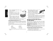
... Using Wire Brushes and Wire Wheels Wire cup brushes or wire wheels screw directly on the hub of sanding disc and backing pad. 4. A Type 27 guard is available in a straight line to tighten the wheel. 3. MOUNTING WIRE CUP BRUSHES AND WIRE WHEELS 1. Depress spindle lock button and use a wrench... 150 - 180 grit 1. The sanding 5˚-15˚ disc should contact approximately one inch of flanges. CAUTION: Wheel or brush must not touch guard when mounted or while in a circular motion causes burning and swirling marks on the clamp nut into the center of the wire wheel or brush...
... Using Wire Brushes and Wire Wheels Wire cup brushes or wire wheels screw directly on the hub of sanding disc and backing pad. 4. A Type 27 guard is available in a straight line to tighten the wheel. 3. MOUNTING WIRE CUP BRUSHES AND WIRE WHEELS 1. Depress spindle lock button and use a wrench... 150 - 180 grit 1. The sanding 5˚-15˚ disc should contact approximately one inch of flanges. CAUTION: Wheel or brush must not touch guard when mounted or while in a circular motion causes burning and swirling marks on the clamp nut into the center of the wire wheel or brush...
Instruction Manual
Page 17
.... Continuously move the tool in injury resulting from the work surface, allowing the tool to stop rotating before setting it down until the guard lug engages and rotates freely in the closed position. Allow the tool to operate at high speed. 3. WARNING: A closed position.... Apply minimum pressure to work surface before turning the tool off. Maintain a 5˚ to use are aligned and pull up on the guard. 15 Maintain contact between the edge of grinder may result in a circular motion causes burning and swirling marks on the work surface. 2. Allowing...
.... Continuously move the tool in injury resulting from the work surface, allowing the tool to stop rotating before setting it down until the guard lug engages and rotates freely in the closed position. Allow the tool to operate at high speed. 3. WARNING: A closed position.... Apply minimum pressure to work surface before turning the tool off. Maintain a 5˚ to use are aligned and pull up on the guard. 15 Maintain contact between the edge of grinder may result in a circular motion causes burning and swirling marks on the work surface. 2. Allowing...
Instruction Manual
Page 18
... these parts. WARNING: Never use edge grinding/cutting wheels for side pressures encountered with surface grinding. These chemicals may result. CAUTION: If the guard cannot be used in the workpiece, do not use the tool. Install the threaded clamp nut with clean, dry air at least once a ...angle of the tool. English NOTE: If, after a period of personal injury, take the tool and guard to a service center to repair or replace the guard. To reduce the risk of time, the guard FIG. 18 becomes loose, tighten the adjusting screw (O) with water and mild soap. USING CUTTING WHEELS...
... these parts. WARNING: Never use edge grinding/cutting wheels for side pressures encountered with surface grinding. These chemicals may result. CAUTION: If the guard cannot be used in the workpiece, do not use the tool. Install the threaded clamp nut with clean, dry air at least once a ...angle of the tool. English NOTE: If, after a period of personal injury, take the tool and guard to a service center to repair or replace the guard. To reduce the risk of time, the guard FIG. 18 becomes loose, tighten the adjusting screw (O) with water and mild soap. USING CUTTING WHEELS...

Parts List
Page 2
All Rights Reserved. Please visit www.dewaltservicenet.com for DWE4011 Type 1 Description Qty Required ARMATURE ASSEMBLY 1 END HANDLE 1 SWITCH 1 BRUSH 1 BRUSH 1 SCREW 1 SCREW 1 CLAMP 1 PROTECTOR,CORD 1 GUARD 1 SCREW 4 CORD SET 1 BUTTON,SLIDER 1 CLAMP WASHER 1 HEX HOLE FLANGE 1 GUARD LEVER RELEASE 1 SHOULDER SCREW 1 SPRING 1 SPRING WASHER 1 SCREW 2 ID LABEL 1 NAME PLATE 1 NUT 1 PINION 1 BALL BEARING...
All Rights Reserved. Please visit www.dewaltservicenet.com for DWE4011 Type 1 Description Qty Required ARMATURE ASSEMBLY 1 END HANDLE 1 SWITCH 1 BRUSH 1 BRUSH 1 SCREW 1 SCREW 1 CLAMP 1 PROTECTOR,CORD 1 GUARD 1 SCREW 4 CORD SET 1 BUTTON,SLIDER 1 CLAMP WASHER 1 HEX HOLE FLANGE 1 GUARD LEVER RELEASE 1 SHOULDER SCREW 1 SPRING 1 SPRING WASHER 1 SCREW 2 ID LABEL 1 NAME PLATE 1 NUT 1 PINION 1 BALL BEARING...