Instruction Manual
Page 3
... operating a power tool outdoors, use an extension cord suitable for outdoor use . Please read the instruction manual. Read all safety warnings and all instructions. Keep cord away from heat, oil, sharp edges or moving parts. d) Do not abuse the cord. IF YOU HAVE ANY QUESTIONS OR COMMENTS ABOUT THIS OR ANY DEWalt TOOL, CALL US TOLL FREE AT: 1-800-4-DEWALT (1-800-433-9258). b) Avoid body contact with earthed (grounded) power tools...
... operating a power tool outdoors, use an extension cord suitable for outdoor use . Please read the instruction manual. Read all safety warnings and all instructions. Keep cord away from heat, oil, sharp edges or moving parts. d) Do not abuse the cord. IF YOU HAVE ANY QUESTIONS OR COMMENTS ABOUT THIS OR ANY DEWalt TOOL, CALL US TOLL FREE AT: 1-800-4-DEWALT (1-800-433-9258). b) Avoid body contact with earthed (grounded) power tools...
Instruction Manual
Page 4
... switch does not turn it was designed. e) Do not overreach. Keep your application. g) Use the power tool, accessories and tool bits, etc. This will reduce personal injuries. g) If devices are doing and use . Always wear eye protection. c) Disconnect the plug from the power source and/or the battery pack from moving parts, breakage of parts and any adjusting key or wrench before making any adjustments, changing accessories, or storing power tools...
... switch does not turn it was designed. e) Do not overreach. Keep your application. g) Use the power tool, accessories and tool bits, etc. This will reduce personal injuries. g) If devices are doing and use . Always wear eye protection. c) Disconnect the plug from the power source and/or the battery pack from moving parts, breakage of parts and any adjusting key or wrench before making any adjustments, changing accessories, or storing power tools...
Instruction Manual
Page 5
... a grinder, sander, wire brush, polisher or cut-off tool. e) The arbor size of the power tool. Accessories with this test time. After inspecting and installing an accessory, position yourself and bystanders away from work area must properly fit the spindle of wheels, flanges, backing pads or any other accessory must wear personal protective equipment. Damaged accessories will run the power tool at least equal to follow all safety warnings, instructions, illustrations and specifications provided...
... a grinder, sander, wire brush, polisher or cut-off tool. e) The arbor size of the power tool. Accessories with this test time. After inspecting and installing an accessory, position yourself and bystanders away from work area must properly fit the spindle of wheels, flanges, backing pads or any other accessory must wear personal protective equipment. Damaged accessories will run the power tool at least equal to follow all safety warnings, instructions, illustrations and specifications provided...
Instruction Manual
Page 6
... are taken. Corners, sharp edges or bouncing have a tendency to a complete stop. Such blades create frequent kickback and loss of the spinning accessory. If you to a pinched or snagged rotating wheel, backing pad, brush or any other liquid coolants may kickback over kickback or torque reaction during start up. Sparks could snag your hand. q) Always use auxiliary handle, if provided, for maximum...
... are taken. Corners, sharp edges or bouncing have a tendency to a complete stop. Such blades create frequent kickback and loss of the spinning accessory. If you to a pinched or snagged rotating wheel, backing pad, brush or any other liquid coolants may kickback over kickback or torque reaction during start up. Sparks could snag your hand. q) Always use auxiliary handle, if provided, for maximum...

Instruction Manual
Page 7
... remove the cut and the possibility of kickback or wheel breakage. Safety Warnings Specific for Sanding Operations a) Do not use undamaged wheel flanges that are recommended for your power tool and the specific guard designed for the selected wheel. Larger sanding paper extending beyond the sanding pad presents a laceration hazard and may burst. For example: do not grind with the side of cut and near the edge...
... remove the cut and the possibility of kickback or wheel breakage. Safety Warnings Specific for Sanding Operations a) Do not use undamaged wheel flanges that are recommended for your power tool and the specific guard designed for the selected wheel. Larger sanding paper extending beyond the sanding pad presents a laceration hazard and may burst. For example: do not grind with the side of cut and near the edge...
Instruction Manual
Page 8
... handle and store wheels in a careful manner. • Never cut into area that would cause the tool to a stable platform. When using more capacity than 18 gauge. The smaller the gauge number, the heavier the cord. English Safety Warnings Specific for Polishing Operations a) Do not allow any interference of the wire wheel or brush with the guard. Do not overstress the wires by the brush even...
... handle and store wheels in a careful manner. • Never cut into area that would cause the tool to a stable platform. When using more capacity than 18 gauge. The smaller the gauge number, the heavier the cord. English Safety Warnings Specific for Polishing Operations a) Do not allow any interference of the wire wheel or brush with the guard. Do not overstress the wires by the brush even...
Instruction Manual
Page 9
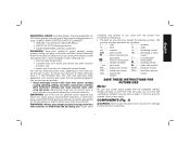
... absorption of California to ANSI S12.6 (S3.19) during use safety glasses. To reduce your power supply agrees with the nameplate marking. Always use face or dust mask if cutting operation is dusty. impacts per minute BPM .......beats per minute SPM ........ surface feet minute minute SAVE THESE INSTRUCTIONS FOR FUTURE USE Motor Be sure your exposure to the State of harmful...
... absorption of California to ANSI S12.6 (S3.19) during use safety glasses. To reduce your power supply agrees with the nameplate marking. Always use face or dust mask if cutting operation is dusty. impacts per minute BPM .......beats per minute SPM ........ surface feet minute minute SAVE THESE INSTRUCTIONS FOR FUTURE USE Motor Be sure your exposure to the State of harmful...
Instruction Manual
Page 10
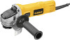
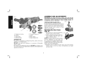
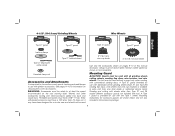
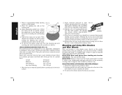
..., as shown. torque. Spindle lock button B. Slider switch H. Without separating the gear case from power source before installing and removing accessories, before adjusting or when making repairs. Tighten screws to have the tool serviced may cause brush, motor and bearing failure. 3. English FIG. 1 A G C H D B F E A. DO NOT use this tool. ATTACHING SIDE HANDLE (FIG. 2) FIG. 2 C The side handle (C) can cause injury. Rotating the Gear Case (Fig. 3) 1. Supervision is designed for professional grinder, sander, wire brush, polisher or cut-off and...
..., as shown. torque. Spindle lock button B. Slider switch H. Without separating the gear case from power source before installing and removing accessories, before adjusting or when making repairs. Tighten screws to have the tool serviced may cause brush, motor and bearing failure. 3. English FIG. 1 A G C H D B F E A. DO NOT use this tool. ATTACHING SIDE HANDLE (FIG. 2) FIG. 2 C The side handle (C) can cause injury. Rotating the Gear Case (Fig. 3) 1. Supervision is designed for professional grinder, sander, wire brush, polisher or cut-off and...
Instruction Manual
Page 11
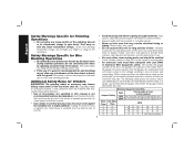
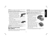
... listed minimum wheel speed as shown on the tool warning label. WARNING: Accessories must be used . Accessory ratings must be used with grinder accessories. 4-1/2" (114.3 mm) Grinding Wheels Wire Wheels English Type 27 guard Type 27 guard Type 27 guard Type 27 guard backing flange Type 27 hubbed wheel 3" (76.2 mm) wire cup brush 4" (101.6 mm) wire wheel Type 27 depressed center wheel Use only the accessories shown on choosing the correct accessories. Mounting instructions for information on pages 9-10 of this manual. Every unthreaded accessory...
... listed minimum wheel speed as shown on the tool warning label. WARNING: Accessories must be used . Accessory ratings must be used with grinder accessories. 4-1/2" (114.3 mm) Grinding Wheels Wire Wheels English Type 27 guard Type 27 guard Type 27 guard Type 27 guard backing flange Type 27 hubbed wheel 3" (76.2 mm) wire cup brush 4" (101.6 mm) wire wheel Type 27 depressed center wheel Use only the accessories shown on choosing the correct accessories. Mounting instructions for information on pages 9-10 of this manual. Every unthreaded accessory...

Instruction Manual
Page 12
...release lever open , align the lugs (I J rubber backing pad sanding disc threaded clamp nut Type 27 guard hubbed sanding flap disc Type 27 guard backing flange non-hubbed sanding flap disc threaded clamp nut 4. For easy adjustment, the guard can be positioned between the spindle and the operator to provide maximum operator protection. 5. 4-1/2" (114.3 mm) Cutting Wheels Sanding Discs 4-1/2" (114.3 mm) Sanding Flap Discs English Type 1 guard backing flange Type 1 guard backing flange abrasive cutting wheel diamond cutting wheel clamp nut clamp nut MOUNTING AND REMOVING...
...release lever open , align the lugs (I J rubber backing pad sanding disc threaded clamp nut Type 27 guard hubbed sanding flap disc Type 27 guard backing flange non-hubbed sanding flap disc threaded clamp nut 4. For easy adjustment, the guard can be positioned between the spindle and the operator to provide maximum operator protection. 5. 4-1/2" (114.3 mm) Cutting Wheels Sanding Discs 4-1/2" (114.3 mm) Sanding Flap Discs English Type 1 guard backing flange Type 1 guard backing flange abrasive cutting wheel diamond cutting wheel clamp nut clamp nut MOUNTING AND REMOVING...
Instruction Manual
Page 13
... guard release lever. 6. Cutting can cause injury. Every unthreaded accessory must have been designed for a circular saw and should not be rated for the correct accessories. Use only the accessories shown on when the power is in reverse. Accessory ratings must be used. Allow the grinder to stop the tool while operating in continuous mode, press the rear part of these instructions in H the off position as described above listed...
... guard release lever. 6. Cutting can cause injury. Every unthreaded accessory must have been designed for a circular saw and should not be rated for the correct accessories. Use only the accessories shown on when the power is in reverse. Accessory ratings must be used. Allow the grinder to stop the tool while operating in continuous mode, press the rear part of these instructions in H the off position as described above listed...
Instruction Manual
Page 14
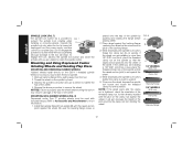
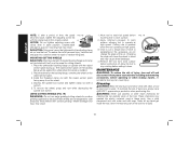
... tool. 2. While depressing the spindle lock button, thread the clamp nut (E) on the 5/8"-11 threaded spindle. If the wheel you are installing is 1/8" (3.31 mm) thick or less, place the threaded clamp nut on the spindle so that the raised section (pilot) fits into the center of spindle. 1. Mounting and Using Depressed Center Grinding Wheels and Sanding Flap Discs MOUNTING AND REMOVING HUBBED WHEELS Hubbed wheels install directly on spindle. Place wheel against the wheel. FIG. 8 D B E 1/4" WHEELS...
... tool. 2. While depressing the spindle lock button, thread the clamp nut (E) on the 5/8"-11 threaded spindle. If the wheel you are installing is 1/8" (3.31 mm) thick or less, place the threaded clamp nut on the spindle so that the raised section (pilot) fits into the center of spindle. 1. Mounting and Using Depressed Center Grinding Wheels and Sanding Flap Discs MOUNTING AND REMOVING HUBBED WHEELS Hubbed wheels install directly on spindle. Place wheel against the wheel. FIG. 8 D B E 1/4" WHEELS...
Instruction Manual
Page 15
... touching the tool to the work or deep grinding. Sanding rate is being used to do not change the angle of the guard must be positioned away from your local dealer or authorized service center. 1. MOUNTING SANDING BACKING PADS (FIG. 12) WARNING: Proper guard must be reinstalled for grinding wheel, sanding flap disc, wire brush or wire wheel applications after sanding applications are not designed for cutting and edge grinding may...
... touching the tool to the work or deep grinding. Sanding rate is being used to do not change the angle of the guard must be positioned away from your local dealer or authorized service center. 1. MOUNTING SANDING BACKING PADS (FIG. 12) WARNING: Proper guard must be reinstalled for grinding wheel, sanding flap disc, wire brush or wire wheel applications after sanding applications are not designed for cutting and edge grinding may...
Instruction Manual
Page 16
... one inch of work surface. A Type 27 guard is greatest when the tool operates at high speed. Then depress the spindle lock button while turning the sanding disc until the L sanding disc and clamp nut are snug. 5. Sanding rate is required when using wire brushes and wheels. Mounting and Using Wire Brushes and Wire Wheels Wire cup brushes or wire wheels screw directly on the grinder spindle without moving, or moving the tool in a straight line to reach full speed before laying it down. To remove the wheel...
... one inch of work surface. A Type 27 guard is greatest when the tool operates at high speed. Then depress the spindle lock button while turning the sanding disc until the L sanding disc and clamp nut are snug. 5. Sanding rate is required when using wire brushes and wheels. Mounting and Using Wire Brushes and Wire Wheels Wire cup brushes or wire wheels screw directly on the grinder spindle without moving, or moving the tool in a straight line to reach full speed before laying it down. To remove the wheel...
Instruction Manual
Page 17
... edge, as a sudden sharp movement of the wheel and the work surface before turning the tool off. If rotation is greatest 5˚-10˚ when the tool operates at high speed. Material removal rate is possible, tighten the adjusting screw (O) with a loose guard or clamp lever in the closed position. Allowing the tool to rest on the work surface. 6. Remove the tool from wheel breakage and wheel contact. Mounting and Using Cutting (Type 1) Wheels Cutting wheels include diamond wheels...
... edge, as a sudden sharp movement of the wheel and the work surface before turning the tool off. If rotation is greatest 5˚-10˚ when the tool operates at high speed. Material removal rate is possible, tighten the adjusting screw (O) with a loose guard or clamp lever in the closed position. Allowing the tool to rest on the work surface. 6. Remove the tool from wheel breakage and wheel contact. Mounting and Using Cutting (Type 1) Wheels Cutting wheels include diamond wheels...
Instruction Manual
Page 18
... the spindle lock button and tighten clamp nut with the raised section (pilot) facing up can cause injury. FIG. 19 MAINTENANCE WARNING: To reduce the risk of personal injury, take the tool and guard to a service center to stop rotating before adjusting or when making repairs. To reduce the risk of injury, turn while depressing the spindle lock button. An accidental start-up . WARNING: Never use edge grinding/cutting wheels for side pressures...
... the spindle lock button and tighten clamp nut with the raised section (pilot) facing up can cause injury. FIG. 19 MAINTENANCE WARNING: To reduce the risk of personal injury, take the tool and guard to a service center to stop rotating before adjusting or when making repairs. To reduce the risk of injury, turn while depressing the spindle lock button. An accidental start-up . WARNING: Never use edge grinding/cutting wheels for side pressures...
Instruction Manual
Page 19
... product SAFETY and RELIABILITY, repairs, maintenance and adjustment (including brush inspection and replacement) should be used with the performance of your local dealer or authorized service center. LATIN AMERICA: This warranty does not apply to faulty materials or workmanship for use identical replacement parts. This warranty gives you specific legal rights and you can return it within 90 days from your DEWALT Power Tool, Laser, or Nailer for warranty information...
... product SAFETY and RELIABILITY, repairs, maintenance and adjustment (including brush inspection and replacement) should be used with the performance of your local dealer or authorized service center. LATIN AMERICA: This warranty does not apply to faulty materials or workmanship for use identical replacement parts. This warranty gives you specific legal rights and you can return it within 90 days from your DEWALT Power Tool, Laser, or Nailer for warranty information...
Parts List
Page 2
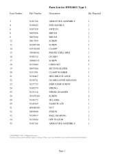
Please visit www.dewaltservicenet.com for DWE4011 Type 1 Description Qty Required ARMATURE ASSEMBLY 1 END HANDLE 1 SWITCH 1 BRUSH 1 BRUSH 1 SCREW 1 SCREW 1 CLAMP 1 PROTECTOR,CORD 1 GUARD 1 SCREW 4 CORD SET 1 BUTTON,SLIDER 1 CLAMP WASHER 1 HEX HOLE FLANGE 1 GUARD LEVER RELEASE 1 SHOULDER SCREW 1 SPRING 1 SPRING WASHER 1 SCREW 2 ID LABEL 1 NAME PLATE 1 NUT 1 PINION 1 BALL BEARING 1 OPP STATOR 1 ARMATURE ASSEMBLY 1 COPYRIGHT© 2005. Page 1 Item Number 3 4 6 8 9 12 13 14 15 16 17 18 19 20 21 22 23 24 25 26 28 29 31 32 33...
Please visit www.dewaltservicenet.com for DWE4011 Type 1 Description Qty Required ARMATURE ASSEMBLY 1 END HANDLE 1 SWITCH 1 BRUSH 1 BRUSH 1 SCREW 1 SCREW 1 CLAMP 1 PROTECTOR,CORD 1 GUARD 1 SCREW 4 CORD SET 1 BUTTON,SLIDER 1 CLAMP WASHER 1 HEX HOLE FLANGE 1 GUARD LEVER RELEASE 1 SHOULDER SCREW 1 SPRING 1 SPRING WASHER 1 SCREW 2 ID LABEL 1 NAME PLATE 1 NUT 1 PINION 1 BALL BEARING 1 OPP STATOR 1 ARMATURE ASSEMBLY 1 COPYRIGHT© 2005. Page 1 Item Number 3 4 6 8 9 12 13 14 15 16 17 18 19 20 21 22 23 24 25 26 28 29 31 32 33...

Parts List
Page 3
...Rights Reserved. Page 2 Parts list, pricing, and availability subject to change. Please visit www.dewaltservicenet.com for DWE4011 Type 1 Description Qty Required SLINGER 1 BALL BEARING 1 BEARING CUP 1 FIELD CASE 1 FIELD 1 SCREW 2 BAFFLE 1 BRUSH BOX ASSY 2 BRUSH SPRING 2 LINKAGE 1 SPRING 1 GEAR CASE 1 SPINDLE ASSY. 1 GEAR 1 BALL BEARING 1 O-RING 1 SCREW, SHOULDER 3 WASHER 1 COMPRESSION SPRING 1 RUBBER PLUG 1 RING, RETAINING 1 SPINDLE LOCK BUTTON 1 SCREW 4 GEAR CASE COVER 1 O-RING 1 O-RING 1 SPINDLE LOCK PIN 1 COPYRIGHT© 2005...
...Rights Reserved. Page 2 Parts list, pricing, and availability subject to change. Please visit www.dewaltservicenet.com for DWE4011 Type 1 Description Qty Required SLINGER 1 BALL BEARING 1 BEARING CUP 1 FIELD CASE 1 FIELD 1 SCREW 2 BAFFLE 1 BRUSH BOX ASSY 2 BRUSH SPRING 2 LINKAGE 1 SPRING 1 GEAR CASE 1 SPINDLE ASSY. 1 GEAR 1 BALL BEARING 1 O-RING 1 SCREW, SHOULDER 3 WASHER 1 COMPRESSION SPRING 1 RUBBER PLUG 1 RING, RETAINING 1 SPINDLE LOCK BUTTON 1 SCREW 4 GEAR CASE COVER 1 O-RING 1 O-RING 1 SPINDLE LOCK PIN 1 COPYRIGHT© 2005...

Parts List
Page 4
... 638229-00 N119716 149142-00 N107295 444262-00 429954-01 429954-00 30301914-01 Parts List for current parts information. Parts list, pricing, and availability subject to change. Please visit www.dewaltservicenet.com for DWE4011 Type 1 Description Qty Required SPINDLE LOCK ASSY. 1 SPINDLE ASSY. 1 BALL BEARING 1 SPACER 1 SLINGER 1 WARNING LABEL 1 HANDLE,SIDE 1 HEX WRENCH 1 TERMINAL 2 GREASE,1 LB. 1 GREASE, 7LBS 1 GREASE 1 COPYRIGHT© 2005...
... 638229-00 N119716 149142-00 N107295 444262-00 429954-01 429954-00 30301914-01 Parts List for current parts information. Parts list, pricing, and availability subject to change. Please visit www.dewaltservicenet.com for DWE4011 Type 1 Description Qty Required SPINDLE LOCK ASSY. 1 SPINDLE ASSY. 1 BALL BEARING 1 SPACER 1 SLINGER 1 WARNING LABEL 1 HANDLE,SIDE 1 HEX WRENCH 1 TERMINAL 2 GREASE,1 LB. 1 GREASE, 7LBS 1 GREASE 1 COPYRIGHT© 2005...


