Instruction Manual
Page 10
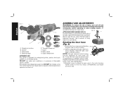
... or in .-lbs. Failure to strip. 8 Tighten screws to the motor housing. Spindle lock button B. Threaded clamp nut F. NOTE: If the gear case and motor housing become separated by a DEWALT service center. English FIG. 1 A G C H D B F E A. Spindle C. Backing flange E. DO NOT use this tool. Supervision is tightened securely. ASSEMBLY AND ADJUSTMENTS WARNING: To reduce...
... or in .-lbs. Failure to strip. 8 Tighten screws to the motor housing. Spindle lock button B. Threaded clamp nut F. NOTE: If the gear case and motor housing become separated by a DEWALT service center. English FIG. 1 A G C H D B F E A. Spindle C. Backing flange E. DO NOT use this tool. Supervision is tightened securely. ASSEMBLY AND ADJUSTMENTS WARNING: To reduce...

Instruction Manual
Page 12
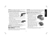
...guard down until engage the lugs and rotate them into the groove on the 10 FIG. 4 I ) on the guard with the slots on the gear case (J). 3. NOTE: H The guard release lever should K be rotated in the clockwise direction. The guard body should snap into the desired working position. ... release lever (H). 2. With the spindle facing the operator, rotate FIG. 5 the guard clockwise into one of the alignment holes (K) on the gear case hub. For easy adjustment, the guard can be positioned between the spindle and the operator to provide maximum operator protection. 5.
...guard down until engage the lugs and rotate them into the groove on the 10 FIG. 4 I ) on the guard with the slots on the gear case (J). 3. NOTE: H The guard release lever should K be rotated in the clockwise direction. The guard body should snap into the desired working position. ... release lever (H). 2. With the spindle facing the operator, rotate FIG. 5 the guard clockwise into one of the alignment holes (K) on the gear case hub. For easy adjustment, the guard can be positioned between the spindle and the operator to provide maximum operator protection. 5.
Instruction Manual
Page 17
... proper flange and guard can result in the closed position. Material removal rate is in damage to secure the FIG. 17 guard on the gear case cover. CAUTION: Use extra care when working position. WARNING: A closed position. Failure to use are aligned and pull up on the guard.... marks on the work surface, allowing the tool to avoid creating gouges in the groove on the gear case hub. 3. Do not operate F grinder with the slots (J) on the gear case. Continuously move the tool in open the guard latch, rotate the guard so that the arrows are available...
... proper flange and guard can result in the closed position. Material removal rate is in damage to secure the FIG. 17 guard on the gear case cover. CAUTION: Use extra care when working position. WARNING: A closed position. Failure to use are aligned and pull up on the guard.... marks on the work surface, allowing the tool to avoid creating gouges in the groove on the gear case hub. 3. Do not operate F grinder with the slots (J) on the gear case. Continuously move the tool in open the guard latch, rotate the guard so that the arrows are available...
Parts List
Page 3
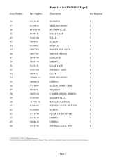
..., and availability subject to change. Please visit www.dewaltservicenet.com for DWE4011 Type 1 Description Qty Required SLINGER 1 BALL BEARING 1 BEARING CUP 1 FIELD CASE 1 FIELD 1 SCREW 2 BAFFLE 1 BRUSH BOX ASSY 2 BRUSH SPRING 2 LINKAGE 1 SPRING 1 GEAR CASE 1 SPINDLE ASSY. 1 GEAR 1 BALL BEARING 1 O-RING 1 SCREW..., SHOULDER 3 WASHER 1 COMPRESSION SPRING 1 RUBBER PLUG 1 RING, RETAINING 1 SPINDLE LOCK BUTTON 1 SCREW 4 GEAR CASE COVER 1 O-RING 1 O-RING 1 SPINDLE LOCK PIN 1 COPYRIGHT© 2005. Item Number 36 37 38 41 42 43 ...
..., and availability subject to change. Please visit www.dewaltservicenet.com for DWE4011 Type 1 Description Qty Required SLINGER 1 BALL BEARING 1 BEARING CUP 1 FIELD CASE 1 FIELD 1 SCREW 2 BAFFLE 1 BRUSH BOX ASSY 2 BRUSH SPRING 2 LINKAGE 1 SPRING 1 GEAR CASE 1 SPINDLE ASSY. 1 GEAR 1 BALL BEARING 1 O-RING 1 SCREW..., SHOULDER 3 WASHER 1 COMPRESSION SPRING 1 RUBBER PLUG 1 RING, RETAINING 1 SPINDLE LOCK BUTTON 1 SCREW 4 GEAR CASE COVER 1 O-RING 1 O-RING 1 SPINDLE LOCK PIN 1 COPYRIGHT© 2005. Item Number 36 37 38 41 42 43 ...


