
Instruction Manual
Page 12
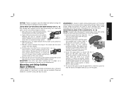
... flange abrasive cutting wheel diamond cutting wheel clamp nut clamp nut MOUNTING AND REMOVING (TYPE 27) ONE-TOUCH™ GUARD (FIG. 4, 5) 1. Release the guard release lever. While holding the guard release lever open , push the guard down until engage the lugs and rotate them into one of the alignment holes (K) on the gear case (J). 3. Keeping the...
... flange abrasive cutting wheel diamond cutting wheel clamp nut clamp nut MOUNTING AND REMOVING (TYPE 27) ONE-TOUCH™ GUARD (FIG. 4, 5) 1. Release the guard release lever. While holding the guard release lever open , push the guard down until engage the lugs and rotate them into one of the alignment holes (K) on the gear case (J). 3. Keeping the...
Instruction Manual
Page 13
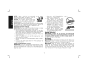
...remove the guard, follow steps 1-3 of these instructions in continuous mode, press the rear part of the tool at least the speed recommended on the tool warning label. Wheels and other accessories running over rated accessory speed may have a 7/8" arbor hole. Accessory ratings must be performed by using a Type 1 wheel and a Type 1 guard... switch toward the front of the tool firmly to a complete stop rotating before putting it from the surface before touching the work surface. An accidental start unexpectedly. Allow the grinder to a power supply, be sure the slider switch...
...remove the guard, follow steps 1-3 of these instructions in continuous mode, press the rear part of the tool at least the speed recommended on the tool warning label. Wheels and other accessories running over rated accessory speed may have a 7/8" arbor hole. Accessory ratings must be performed by using a Type 1 wheel and a Type 1 guard... switch toward the front of the tool firmly to a complete stop rotating before putting it from the surface before touching the work surface. An accidental start unexpectedly. Allow the grinder to a power supply, be sure the slider switch...
Instruction Manual
Page 15
...of serious injury, limit the use a closed, Type 1 guard. Grinding rate is greatest 20˚-30˚ when the tool operates at high speed. 3. Maintain a 5˚ to shallow cutting and notching (less than 1/2" in depth). Remove the tool from the work surface before turning tool off . ...before turning the tool off . Remove the tool from work surface before laying it down. Allow the tool to reach full speed before FIG. 9 touching the tool to the work surface. 2. MOUNTING SANDING BACKING PADS (FIG. 12) WARNING: Proper guard must be reinstalled for grinding wheel,...
...of serious injury, limit the use a closed, Type 1 guard. Grinding rate is greatest 20˚-30˚ when the tool operates at high speed. 3. Maintain a 5˚ to shallow cutting and notching (less than 1/2" in depth). Remove the tool from the work surface before turning tool off . ...before turning the tool off . Remove the tool from work surface before laying it down. Allow the tool to reach full speed before FIG. 9 touching the tool to the work surface. 2. MOUNTING SANDING BACKING PADS (FIG. 12) WARNING: Proper guard must be reinstalled for grinding wheel,...
Instruction Manual
Page 16
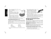
...and sanding pad while depressing the spindle lock button. USING SANDING BACKING PADS (FIG. 13) Choose the proper grit sandpaper for fast, rough material removal. Sandpaper is available in a straight line to reach full speed before laying it down. Coarse 16 - 30 grit Medium 36 - 80 grit ... greatest when the tool operates at high speed. CAUTION: Wear work surface. They can become sharp. CAUTION: Wheel or brush must not touch guard when mounted or while in a circular motion causes burning and swirling marks on the backing pad. 3. Undetectable damage could occur to the ...
...and sanding pad while depressing the spindle lock button. USING SANDING BACKING PADS (FIG. 13) Choose the proper grit sandpaper for fast, rough material removal. Sandpaper is available in a straight line to reach full speed before laying it down. Coarse 16 - 30 grit Medium 36 - 80 grit ... greatest when the tool operates at high speed. CAUTION: Wear work surface. They can become sharp. CAUTION: Wheel or brush must not touch guard when mounted or while in a circular motion causes burning and swirling marks on the backing pad. 3. Undetectable damage could occur to the ...
Instruction Manual
Page 17
... and wheel contact. Allow the tool to secure the FIG. 17 guard on the gear case cover. J 2. Push the guard down . To remove the guard, open position. 5. Allow the tool to reach full speed before FIG. 14 touching the tool to the work surface before turning the tool off. Close... the guard latch to stop rotating before setting it down until the guard lug engages and rotates freely...
... and wheel contact. Allow the tool to secure the FIG. 17 guard on the gear case cover. J 2. Push the guard down . To remove the guard, open position. 5. Allow the tool to reach full speed before FIG. 14 touching the tool to the work surface before turning the tool off. Close... the guard latch to stop rotating before setting it down until the guard lug engages and rotates freely...
Instruction Manual
Page 18
... dirt and dust out of all air vents with the raised section (pilot) facing away from work surface before touching tool to work surface, allowing tool to repair or replace the guard. These chemicals may result. 1. Never let any part of eye injury, always wear ANSI Z87.1 approved eye ...The raised section (pilot) on the raised section (pilot). 3. Install the threaded clamp nut with clean, dry air at least once a week. To remove the wheel, grasp and turn unit off . Apply minimum pressure to bend and may result. Changing the angle will be tightened by the adjusting clamp...
... dirt and dust out of all air vents with the raised section (pilot) facing away from work surface before touching tool to work surface, allowing tool to repair or replace the guard. These chemicals may result. 1. Never let any part of eye injury, always wear ANSI Z87.1 approved eye ...The raised section (pilot) on the raised section (pilot). 3. Install the threaded clamp nut with clean, dry air at least once a week. To remove the wheel, grasp and turn unit off . Apply minimum pressure to bend and may result. Changing the angle will be tightened by the adjusting clamp...


