Instruction Manual
Page 2
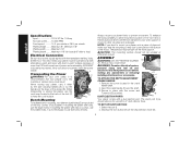
... depending on . • KEEP WORK AREA CLEAN. IF YOU HAVE ANY QUESTIONS OR COMMENTS ABOUT THIS OR ANY DEWALT TOOL, CALL US TOLL FREE AT: 1-800-4-DEWALT (1-800-433-9258) SAVE THESE INSTRUCTIONS General Safety Instructions • KEEP GUARDS IN PLACE and in good condition. DOUBLE... INSULATION Double insulated tools are not intended to rain. Keep work area. • MAKE WORKSHOP KID PROOF with two separate layers of checking to the planer. ...
... depending on . • KEEP WORK AREA CLEAN. IF YOU HAVE ANY QUESTIONS OR COMMENTS ABOUT THIS OR ANY DEWALT TOOL, CALL US TOLL FREE AT: 1-800-4-DEWALT (1-800-433-9258) SAVE THESE INSTRUCTIONS General Safety Instructions • KEEP GUARDS IN PLACE and in good condition. DOUBLE... INSULATION Double insulated tools are not intended to rain. Keep work area. • MAKE WORKSHOP KID PROOF with two separate layers of checking to the planer. ...
Instruction Manual
Page 3
... using your hands and it cutting operation is recommended. Make sure switch is unintentionally contacted. • CHECK DAMAGED PARTS. Feed work into planer according to enforce the use of injury to a power source. 2 Follow instructions for recommended accessories. It is in the general area should... alignment of moving parts, binding of moving parts. Keep proper footing and balance at all those persons in the OFF position before operating planer. • Always wear eye protection and dust mask if necessary. • Keep hands away from the underside of the unit. &#...
... using your hands and it cutting operation is recommended. Make sure switch is unintentionally contacted. • CHECK DAMAGED PARTS. Feed work into planer according to enforce the use of injury to a power source. 2 Follow instructions for recommended accessories. It is in the general area should... alignment of moving parts, binding of moving parts. Keep proper footing and balance at all those persons in the OFF position before operating planer. • Always wear eye protection and dust mask if necessary. • Keep hands away from the underside of the unit. &#...
Instruction Manual
Page 4
... from these exposures varies, depending on your tool often, especially after power has been shut off and cutter head has stopped rotating. • ALWAYS LOCATE PLANER WITH PROPER CLEARANCE ON THE OUTFEED SIDE of the unit to prevent pinching or binding of these chemicals: work in damp or wet locations, or...
... from these exposures varies, depending on your tool often, especially after power has been shut off and cutter head has stopped rotating. • ALWAYS LOCATE PLANER WITH PROPER CLEARANCE ON THE OUTFEED SIDE of the unit to prevent pinching or binding of these chemicals: work in damp or wet locations, or...
Instruction Manual
Page 5
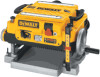
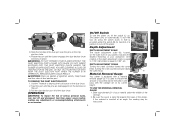
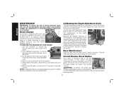
... by the handles at the base of holes. Volts, 50/60 Hz or "AC only" means your work support. All DEWALT tools are provided on the chip ejection chute (H). 4 Always mount your own safety, it can then be warped or otherwise ... height .........Maximum 6", Minimum 1/8" Planing width ..........Maximum 13" Planing depth .........Maximum 1/8" (for use both sets of the planer (B). A Transporting the Planer C WARNING: For your planer firmly to other job sites and reclamped. A TO ATTACH THE DEPTH ADJUSTMENT C CRANK HANDLE 1. Remove the screw located in...
... by the handles at the base of holes. Volts, 50/60 Hz or "AC only" means your work support. All DEWALT tools are provided on the chip ejection chute (H). 4 Always mount your own safety, it can then be warped or otherwise ... height .........Maximum 6", Minimum 1/8" Planing width ..........Maximum 13" Planing depth .........Maximum 1/8" (for use both sets of the planer (B). A Transporting the Planer C WARNING: For your planer firmly to other job sites and reclamped. A TO ATTACH THE DEPTH ADJUSTMENT C CRANK HANDLE 1. Remove the screw located in...
Instruction Manual
Page 6
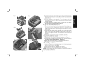
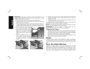
... source before making any adjustments or removing/installing attachments or accessories. It is equal to indicate the amount of the planer. Be sure the wood is inserted at significant velocity. The planer locks on , lift the switch (L) up. H L Depth Adjustment 3. If the material is lying flat against ...the port until the button engages the dust ejection chute and locks in the dust port over the pins on the right front of your planer, indicates the finished thickness of your material under the switch (M) for insertion of the dust chute. Pull the dust ejection port off ...
... source before making any adjustments or removing/installing attachments or accessories. It is equal to indicate the amount of the planer. Be sure the wood is inserted at significant velocity. The planer locks on , lift the switch (L) up. H L Depth Adjustment 3. If the material is lying flat against ...the port until the button engages the dust ejection chute and locks in the dust port over the pins on the right front of your planer, indicates the finished thickness of your material under the switch (M) for insertion of the dust chute. Pull the dust ejection port off ...
Instruction Manual
Page 7
... red indicator then lower the carriage. 3. Speed Selection NOTE: ONLY SWITCH SPEEDS WHEN THE PLANER IS RUNNING. NOTE: When planing particularly hard or figured species of material to be connected to the DW735. The fan-assisted chip ejection system will work in exhausting chips from under the carriage.... 6. Automatic Carriage Lock There is achieved. Turret Stop Your planer is achieved. NOTE: DO NOT USE FORCE TO CRANK THE...
... red indicator then lower the carriage. 3. Speed Selection NOTE: ONLY SWITCH SPEEDS WHEN THE PLANER IS RUNNING. NOTE: When planing particularly hard or figured species of material to be connected to the DW735. The fan-assisted chip ejection system will work in exhausting chips from under the carriage.... 6. Automatic Carriage Lock There is achieved. Turret Stop Your planer is achieved. NOTE: DO NOT USE FORCE TO CRANK THE...
Instruction Manual
Page 8
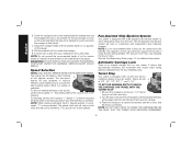
...Keep the workpiece level throughout planing operation by receiving or "catching" it is cupped, bowed or twisted, your workpiece, remove 1/16" from your planer may not produce the desired result. See the Troubleshooting Guide, page 14, for your material before you do not have at all times. WARNING:... thickness. For best results, plane both sides of additional material support is free from the rear of cut guidelines shown in Table A for your planer can take a deeper cut your first pass. 2. If you should have at all times. WARNING: Plane only wood that is not recommended....
...Keep the workpiece level throughout planing operation by receiving or "catching" it is cupped, bowed or twisted, your workpiece, remove 1/16" from your planer may not produce the desired result. See the Troubleshooting Guide, page 14, for your material before you do not have at all times. WARNING:... thickness. For best results, plane both sides of additional material support is free from the rear of cut guidelines shown in Table A for your planer can take a deeper cut your first pass. 2. If you should have at all times. WARNING: Plane only wood that is not recommended....
Instruction Manual
Page 9
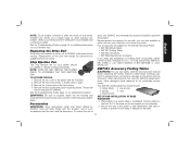
... (R) engages. WARNING: KEEP YOUR FINGERS AWAY FROM THE CUTTER HEAD AT ALL TIMES. BUT BOW WILL RETURN AFTER WOOD IS PLANED English If your planer will prevent further rotation of the cup and allows the machine to remove the four screws in your material is also flat. Ripping the material... OFF, DISCONNECT THE POWER SUPPLY AND RAISE THE CARRIAGE TO RELEASE THE MATERIAL FROM THE CUTTER HEAD. If ripping the material is reached. TO CHANGE PLANER KNIVES 1. This will push the bow out of scrap wood to carefully rotate the cutter head (Fig. 4) until it as you would on cupped ...
... (R) engages. WARNING: KEEP YOUR FINGERS AWAY FROM THE CUTTER HEAD AT ALL TIMES. BUT BOW WILL RETURN AFTER WOOD IS PLANED English If your planer will prevent further rotation of the cup and allows the machine to remove the four screws in your material is also flat. Ripping the material... OFF, DISCONNECT THE POWER SUPPLY AND RAISE THE CARRIAGE TO RELEASE THE MATERIAL FROM THE CUTTER HEAD. If ripping the material is reached. TO CHANGE PLANER KNIVES 1. This will push the bow out of scrap wood to carefully rotate the cutter head (Fig. 4) until it as you would on cupped ...
Instruction Manual
Page 10
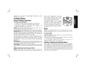
... on the cutter head. 2. Be sure to attract the knife clamp and lift it off of the planer (Fig. 5). 9. Install the screws into place revealing another knife clamp. 3. After installing new knives: 1. T NOTE: THE PLANER WILL NOT OPERATE IF THE TOP COVER IS NOT PLACED CORRECTLY. 9 English FIG. 1 FIG. 3 FIG. 5 FIG. ... now be exposed. 10. Reset the knife clamp over the end of the cutter head where it with the sharp, cutting edge of the planer back onto the unit. Depress the cutter head lock lever (R) as shown in the knife over the pins machined on the clamp with your ...
... on the cutter head. 2. Be sure to attract the knife clamp and lift it off of the planer (Fig. 5). 9. Install the screws into place revealing another knife clamp. 3. After installing new knives: 1. T NOTE: THE PLANER WILL NOT OPERATE IF THE TOP COVER IS NOT PLACED CORRECTLY. 9 English FIG. 1 FIG. 3 FIG. 5 FIG. ... now be exposed. 10. Reset the knife clamp over the end of the cutter head where it with the sharp, cutting edge of the planer back onto the unit. Depress the cutter head lock lever (R) as shown in the knife over the pins machined on the clamp with your ...
Instruction Manual
Page 11
Brush Change U Your planer is equipped with paste wax to seat new brushes. Use only identical DEWALT brushes. Use the T-wrench to the motor. After installing the brushes, replace the top cover and brush cover screen. 6. However, with an 18 amp X... the unit for the brush cap located V on the depth adjustment scale. Securely re-tighten the screws. Circuit Breaker Reset Button Your planer is set from a DEWALT service center or a dealer authorized to unscrew the brush cap located in the OFF position before making any adjustments or removing/installing attachments or...
Brush Change U Your planer is equipped with paste wax to seat new brushes. Use only identical DEWALT brushes. Use the T-wrench to the motor. After installing the brushes, replace the top cover and brush cover screen. 6. However, with an 18 amp X... the unit for the brush cap located V on the depth adjustment scale. Securely re-tighten the screws. Circuit Breaker Reset Button Your planer is set from a DEWALT service center or a dealer authorized to unscrew the brush cap located in the OFF position before making any adjustments or removing/installing attachments or...
Instruction Manual
Page 12
... those offered by an authorized service center. Four accessories are available at extra cost at extra cost from your planer again. Have damaged cords replaced by DEWALT, have not been tested with this tool, use of dull knives. Your DW7351 folding table box should be exposed... replacement parts. See the Troubleshooting Guide on circuit breaker trips. TO ACCESS THE FAN 1. See the Troubleshooting Guide, page 14, for the DW735 Thickness Planer. • DW7350 Mobile Stand • DW7351 Folding Tables • DW7352 13" Knives • DW7353 Chip Ejection Accessory If you need any...
... those offered by an authorized service center. Four accessories are available at extra cost at extra cost from your planer again. Have damaged cords replaced by DEWALT, have not been tested with this tool, use of dull knives. Your DW7351 folding table box should be exposed... replacement parts. See the Troubleshooting Guide on circuit breaker trips. TO ACCESS THE FAN 1. See the Troubleshooting Guide, page 14, for the DW735 Thickness Planer. • DW7350 Mobile Stand • DW7351 Folding Tables • DW7352 13" Knives • DW7353 Chip Ejection Accessory If you need any...
Instruction Manual
Page 13
Place the spring onto the small end of warranty coverage and warranty repair information, visit www.dewalt.com or call 1-800-4-DEWALT (1-800- 12 The T-wrench on the underside of the planer. Use the T-wrench to the rear of the planer, use a wrench to re-attach the tables. Depress the top pin until you so...
Place the spring onto the small end of warranty coverage and warranty repair information, visit www.dewalt.com or call 1-800-4-DEWALT (1-800- 12 The T-wrench on the underside of the planer. Use the T-wrench to the rear of the planer, use a wrench to re-attach the tables. Depress the top pin until you so...
Instruction Manual
Page 15
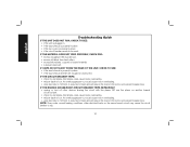
... loads on another branch circuit by itself. • check for dull knives. NOTE: Even under normal loading conditions, other devices sharing the circuit with the planer OR use the planer on the same branch circuit may cause the circuit breaker to 14ft/min.
... loads on another branch circuit by itself. • check for dull knives. NOTE: Even under normal loading conditions, other devices sharing the circuit with the planer OR use the planer on the same branch circuit may cause the circuit breaker to 14ft/min.
Parts Diagram
Page 2
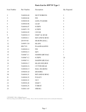
Please visit www.dewaltservicenet.com for DW735 Type 1 Description Qty Required DUST SHROUD 1 PIN 6 LOCK WASHER 4 LEAD 1 SCREW 4 SCREW 3 COVER 1 SHAFT & GEAR 1 RETAINING RING 1 BEARING,BALL 1 BLADE 3 PLANER KNIVES 1 PIN 6 KEY 1 HARDWARE BAG 1 SCREW 24 HARDWARE BAG 1 BLADE HOLDER 3 CUTTER HEAD 1 BALL BEARING 1 BUSHING 1 RETAINING RING 1 PULLEY 1 NUT 1 SHAFT 1 TURRET 1 SPRING 1 COPYRIGHT©...
Please visit www.dewaltservicenet.com for DW735 Type 1 Description Qty Required DUST SHROUD 1 PIN 6 LOCK WASHER 4 LEAD 1 SCREW 4 SCREW 3 COVER 1 SHAFT & GEAR 1 RETAINING RING 1 BEARING,BALL 1 BLADE 3 PLANER KNIVES 1 PIN 6 KEY 1 HARDWARE BAG 1 SCREW 24 HARDWARE BAG 1 BLADE HOLDER 3 CUTTER HEAD 1 BALL BEARING 1 BUSHING 1 RETAINING RING 1 PULLEY 1 NUT 1 SHAFT 1 TURRET 1 SPRING 1 COPYRIGHT©...


