
Instruction Manual
Page 2
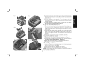
...• REMOVE ADJUSTING KEYS AND WRENCHES. If the plug does not fit fully into the outlet, reverse the plug. The following : to the planer. The smaller the gauge number, the heavier the cord. NOTE: Double insulation does not take the place of electric shock, this equipment has a..., CALL US TOLL FREE AT: 1-800-4-DEWALT (1-800-433-9258) SAVE THESE INSTRUCTIONS General Safety Instructions • KEEP GUARDS IN PLACE and in any way. All visitors should always be kept safe distance from tool before operating the planer. Don't force tool or attachment to heed these ...
...• REMOVE ADJUSTING KEYS AND WRENCHES. If the plug does not fit fully into the outlet, reverse the plug. The following : to the planer. The smaller the gauge number, the heavier the cord. NOTE: Double insulation does not take the place of electric shock, this equipment has a..., CALL US TOLL FREE AT: 1-800-4-DEWALT (1-800-433-9258) SAVE THESE INSTRUCTIONS General Safety Instructions • KEEP GUARDS IN PLACE and in any way. All visitors should always be kept safe distance from tool before operating the planer. Don't force tool or attachment to heed these ...
Instruction Manual
Page 3
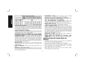
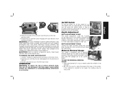
... RESULT IN FLYING DEBRIS, COLLATION MATERIAL, OR DUST WHICH COULD HARM OPERATOR'S EYES. Follow instructions for lubricating and changing accessories. • DISCONNECT TOOLS before operating planer. • Always wear eye protection and dust mask if necessary. • Keep hands away from the underside of the cutter head carriage. • Never clear... 16 14 12 10 12 16 16 14 12 12 16 14 12 Not Recommended • WEAR PROPER APPAREL. Additional Specific Safety Rules for Planers • To reduce the risk of clamps or a vise to hold work into...
... RESULT IN FLYING DEBRIS, COLLATION MATERIAL, OR DUST WHICH COULD HARM OPERATOR'S EYES. Follow instructions for lubricating and changing accessories. • DISCONNECT TOOLS before operating planer. • Always wear eye protection and dust mask if necessary. • Keep hands away from the underside of the cutter head carriage. • Never clear... 16 14 12 10 12 16 16 14 12 12 16 14 12 Not Recommended • WEAR PROPER APPAREL. Additional Specific Safety Rules for Planers • To reduce the risk of clamps or a vise to hold work into...
Instruction Manual
Page 4
... use . Allowing dust to get into your tool often, especially after power has been shut off and cutter head has stopped rotating. • ALWAYS LOCATE PLANER WITH PROPER CLEARANCE ON THE OUTFEED SIDE of the unit to prevent pinching or binding of the workpiece against any obstacle. • Clean out your...
... use . Allowing dust to get into your tool often, especially after power has been shut off and cutter head has stopped rotating. • ALWAYS LOCATE PLANER WITH PROPER CLEARANCE ON THE OUTFEED SIDE of the unit to prevent pinching or binding of the workpiece against any obstacle. • Clean out your...
Instruction Manual
Page 5
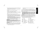
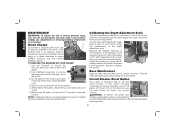
...the nameplate marking. English Specifications Input 120 V AC , 15 Amp No load speed ........10,000 RPM Feed speed 14 ft. All DEWALT tools are provided on the four corners of plywood, make sure that two people carry this tool does not operate, check the power supply. ...result. NOTE: If you elect to a piece of holes. Serious injury could result. Voltage decrease of more than 10% will cause loss of the planer (B). A TO ATTACH THE DEPTH ADJUSTMENT C CRANK HANDLE 1. Insert the crank handle (F) over the shaft. 3. per minute or 26 ft. When transporting ...
...the nameplate marking. English Specifications Input 120 V AC , 15 Amp No load speed ........10,000 RPM Feed speed 14 ft. All DEWALT tools are provided on the four corners of plywood, make sure that two people carry this tool does not operate, check the power supply. ...result. NOTE: If you elect to a piece of holes. Serious injury could result. Voltage decrease of more than 10% will cause loss of the planer (B). A TO ATTACH THE DEPTH ADJUSTMENT C CRANK HANDLE 1. Insert the crank handle (F) over the shaft. 3. per minute or 26 ft. When transporting ...
Instruction Manual
Page 6
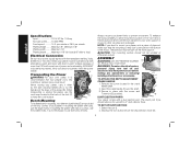
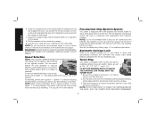
... the crank clockwise lowers the cutter head. To turn the tool off and disconnect tool from the notches on the right front of your planer, indicates the finished thickness of your material under the switch (M) for insertion of your workpiece. Rotate the port until the pins are ejected... used to depress the lock button on the chip ejection chute. 4. DO NOT GET YOUR FACE OR EYES NEAR THE DUST EJECTION PORT WHEN THE PLANER IS IN OPERATION. Use the T-wrench to indicate the amount of the carriage. 2. DEPTH ADJUSTMENT SCALE The depth adjustment scale (N), located on the ...
... the crank clockwise lowers the cutter head. To turn the tool off and disconnect tool from the notches on the right front of your planer, indicates the finished thickness of your material under the switch (M) for insertion of your workpiece. Rotate the port until the pins are ejected... used to depress the lock button on the chip ejection chute. 4. DO NOT GET YOUR FACE OR EYES NEAR THE DUST EJECTION PORT WHEN THE PLANER IS IN OPERATION. Use the T-wrench to indicate the amount of the carriage. 2. DEPTH ADJUSTMENT SCALE The depth adjustment scale (N), located on the ...
Instruction Manual
Page 7
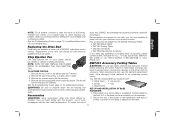
...96 cuts per inch to the material. The capacity of most vacs does not support the volume of material to be connected to the DW735. NOTE: DO NOT USE FORCE TO CRANK THE CARRIAGE BELOW THE LEVEL THAT THE TURRET STOP INDICATES. You will reduce knife wear and...for various widths of material recommended on the front left of chips. See the Troubleshooting Guide, page 14, for ensuring the finest finish on your planer. A device that automatically minimizes the movement that a shop vac be removed with the carriage at desired increments until the desired thickness setting aligns with...
...96 cuts per inch to the material. The capacity of most vacs does not support the volume of material to be connected to the DW735. NOTE: DO NOT USE FORCE TO CRANK THE CARRIAGE BELOW THE LEVEL THAT THE TURRET STOP INDICATES. You will reduce knife wear and...for various widths of material recommended on the front left of chips. See the Troubleshooting Guide, page 14, for ensuring the finest finish on your planer. A device that automatically minimizes the movement that a shop vac be removed with the carriage at desired increments until the desired thickness setting aligns with...
Instruction Manual
Page 8
...one flat surface or a jointer, see the following recommendations. 7 If you plane. English DAMAGE TO THE HEIGHT ADJUSTMENT SYSTEM ON YOUR PLANER WILL RESULT. PLANING BASICS Proper Planing Technique TO PLANE YOUR MATERIAL 1. Turn the unit on and feed the material into the cutter head.... WARNING: Plane only wood that has been run through a jointer to take in Proper Planing Techniques. WARNING: Do not place your planer to produce one wide workpiece whenever possible. Support the workpiece adequately at least one pass is feeding. Planing material less than 6" wide)....
...one flat surface or a jointer, see the following recommendations. 7 If you plane. English DAMAGE TO THE HEIGHT ADJUSTMENT SYSTEM ON YOUR PLANER WILL RESULT. PLANING BASICS Proper Planing Technique TO PLANE YOUR MATERIAL 1. Turn the unit on and feed the material into the cutter head.... WARNING: Plane only wood that has been run through a jointer to take in Proper Planing Techniques. WARNING: Do not place your planer to produce one wide workpiece whenever possible. Support the workpiece adequately at least one pass is feeding. Planing material less than 6" wide)....
Instruction Manual
Page 9
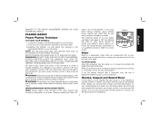
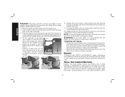
...the dust shroud up so the round connection that seal the dust shroud over the cutter head. 4. Take the dust shroud out of the planer. 2. The cutter head is also flat. BOWED WOOD WILL BE FLATTENED BY FEED ROLLERS AND CUTTER HEAD... ... Push the dust shroud to ...between each pass as it aside. 3. However, when the material exits the planer, the pressure of the material as recommended by the general planing directions. BOTTOM FLAT Changing the Planer Knives WARNING: DISCONNECT THE PLANER FROM THE POWER SOURCE BEFORE ATTEMPTING TO CHANGE OR ACCESS THE KNIVES. Ripping ...
...the dust shroud up so the round connection that seal the dust shroud over the cutter head. 4. Take the dust shroud out of the planer. 2. The cutter head is also flat. BOWED WOOD WILL BE FLATTENED BY FEED ROLLERS AND CUTTER HEAD... ... Push the dust shroud to ...between each pass as it aside. 3. However, when the material exits the planer, the pressure of the material as recommended by the general planing directions. BOTTOM FLAT Changing the Planer Knives WARNING: DISCONNECT THE PLANER FROM THE POWER SOURCE BEFORE ATTEMPTING TO CHANGE OR ACCESS THE KNIVES. Ripping ...
Instruction Manual
Page 10
...another knife clamp. 3. Reset the knife clamp over the pins machined on the top of the dust shroud into place. 2. Use the piece of the planer back onto the unit. Follow the same knife change procedure indicated above. 4. Screw the top cover of scrap wood to remove the eight screws on... head until it will not secure the knife properly. 3. Turn the knife around so that the sharp, unused edge hangs over the end of the planer (Fig. 5). 9. Insert the round end of the T-wrench (Fig. 6) to set them in the small screws bin (S) on the clamp with your fingers. Depress ...
...another knife clamp. 3. Reset the knife clamp over the pins machined on the top of the dust shroud into place. 2. Use the piece of the planer back onto the unit. Follow the same knife change procedure indicated above. 4. Screw the top cover of scrap wood to remove the eight screws on... head until it will not secure the knife properly. 3. Turn the knife around so that the sharp, unused edge hangs over the end of the planer (Fig. 5). 9. Insert the round end of the T-wrench (Fig. 6) to set them in the small screws bin (S) on the clamp with your fingers. Depress ...
Instruction Manual
Page 11
... measurement. TO REPLACE THE BRUSHES ON YOUR PLANER 1. Use a flathead screwdriver to maintain the same orientation when you resume working. English MAINTENANCE WARNING: To reduce the risk of serious personal injury, turn off and disconnect tool from a DEWALT service center or a dealer authorized to be... sure to unscrew the brush cap located in the OFF position before restoring power. 10 Do the same for the brush cap located V on the planer. 2. Place the new brushes into the ...
... measurement. TO REPLACE THE BRUSHES ON YOUR PLANER 1. Use a flathead screwdriver to maintain the same orientation when you resume working. English MAINTENANCE WARNING: To reduce the risk of serious personal injury, turn off and disconnect tool from a DEWALT service center or a dealer authorized to be... sure to unscrew the brush cap located in the OFF position before restoring power. 10 Do the same for the brush cap located V on the planer. 2. Place the new brushes into the ...
Instruction Manual
Page 12
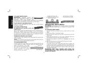
... by an authorized service center. dewalt.com DW7351 Accessory Folding Tables WARNING: For your breaker. When servicing this tool could be cleaned or cleared of dull knives. Have damaged cords replaced by qualified service personnel. Your DW7351 folding table box should be exposed for the DW735 Thickness Planer. • DW7350 Mobile Stand •...
... by an authorized service center. dewalt.com DW7351 Accessory Folding Tables WARNING: For your breaker. When servicing this tool could be cleaned or cleared of dull knives. Have damaged cords replaced by qualified service personnel. Your DW7351 folding table box should be exposed for the DW735 Thickness Planer. • DW7350 Mobile Stand •...
Instruction Manual
Page 13
... repairs, maintenance and adjustment should show on the bottom screw while in the first rib on the side of the base. 5. Three Year Limited Warranty DEWALT will repair, without charge, any defects due to faulty materials or workmanship for planing. Push the stepped bolt all the way through the hole in... due to tighten that two people carry this machine or serious injury could tilt or fall from the table if it . English WARNING: The planer could result. Install the smaller screw into it is not properly secured opposite the end where the folding table is flush with the tables, fold...
... repairs, maintenance and adjustment should show on the bottom screw while in the first rib on the side of the base. 5. Three Year Limited Warranty DEWALT will repair, without charge, any defects due to faulty materials or workmanship for planing. Push the stepped bolt all the way through the hole in... due to tighten that two people carry this machine or serious injury could tilt or fall from the table if it . English WARNING: The planer could result. Install the smaller screw into it is not properly secured opposite the end where the folding table is flush with the tables, fold...
Instruction Manual
Page 15
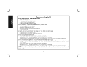
...; excessively twisted, cupped or bowed material. • a broken drive belt. NOTE: Even under normal loading conditions, other devices sharing the circuit with the planer OR use the planer on the motor and prevent breaker trips. IF THE CIRCUIT BREAKER TRIPS: • check for dull knives. An overly aggressive cut could cause motor...
...; excessively twisted, cupped or bowed material. • a broken drive belt. NOTE: Even under normal loading conditions, other devices sharing the circuit with the planer OR use the planer on the motor and prevent breaker trips. IF THE CIRCUIT BREAKER TRIPS: • check for dull knives. An overly aggressive cut could cause motor...
Parts Diagram
Page 2
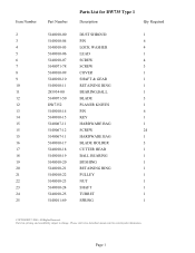
Page 1 Please visit www.dewaltservicenet.com for DW735 Type 1 Description Qty Required DUST SHROUD 1 PIN 6 LOCK WASHER 4 LEAD 1 SCREW 4 SCREW 3 COVER 1 SHAFT & GEAR 1 RETAINING RING 1 BEARING,BALL 1 BLADE 3 PLANER KNIVES 1 PIN 6 KEY 1 HARDWARE BAG 1 SCREW 24 HARDWARE BAG 1 BLADE HOLDER 3 CUTTER HEAD 1 BALL BEARING 1 BUSHING 1 RETAINING RING 1 PULLEY 1 NUT 1 SHAFT 1 TURRET 1 SPRING 1 COPYRIGHT...
Page 1 Please visit www.dewaltservicenet.com for DW735 Type 1 Description Qty Required DUST SHROUD 1 PIN 6 LOCK WASHER 4 LEAD 1 SCREW 4 SCREW 3 COVER 1 SHAFT & GEAR 1 RETAINING RING 1 BEARING,BALL 1 BLADE 3 PLANER KNIVES 1 PIN 6 KEY 1 HARDWARE BAG 1 SCREW 24 HARDWARE BAG 1 BLADE HOLDER 3 CUTTER HEAD 1 BALL BEARING 1 BUSHING 1 RETAINING RING 1 PULLEY 1 NUT 1 SHAFT 1 TURRET 1 SPRING 1 COPYRIGHT...


