
Owners Manual
Page 1
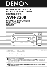
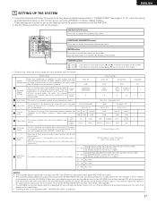
...RECEIVER RÉCEPTEUR AUDIO-VIDÉO AVR-3300 OPERATING INSTRUCTIONS MODE D'EMPLOI B PRECISION AUDIO COMPONENT / AV SURROUND RECEIVER AVR-3300 FUNCTION REMOTE SENSOR ON / STANDBY LOCK AUTO SIGNAL DIGITAL INPUT PCM DTS SOURCE TUNING PRESET REC/ MULTI MD/TAPE MON A SURROUND SPEAKER B VOLUME LEVEL PHONES AUTO PCM INPUT DTS ANALOG EXT. AUDIO DECK MD CD MULTI MUTING AVR/AVC VIDEO.../ B VOLUME DISC SKIP+ SPEAKER DOLBY / DTS SURROUND DIRECT DSP SIMULATION 5CH STEREO INPUT MODE ANALOG STEREO EXT.IN MASTER VOL. IN VIDEO SELECT DIMMER STATUS MASTER VOLUME SURROUND MODE...
...RECEIVER RÉCEPTEUR AUDIO-VIDÉO AVR-3300 OPERATING INSTRUCTIONS MODE D'EMPLOI B PRECISION AUDIO COMPONENT / AV SURROUND RECEIVER AVR-3300 FUNCTION REMOTE SENSOR ON / STANDBY LOCK AUTO SIGNAL DIGITAL INPUT PCM DTS SOURCE TUNING PRESET REC/ MULTI MD/TAPE MON A SURROUND SPEAKER B VOLUME LEVEL PHONES AUTO PCM INPUT DTS ANALOG EXT. AUDIO DECK MD CD MULTI MUTING AVR/AVC VIDEO.../ B VOLUME DISC SKIP+ SPEAKER DOLBY / DTS SURROUND DIRECT DSP SIMULATION 5CH STEREO INPUT MODE ANALOG STEREO EXT.IN MASTER VOL. IN VIDEO SELECT DIMMER STATUS MASTER VOLUME SURROUND MODE...
Owners Manual
Page 5
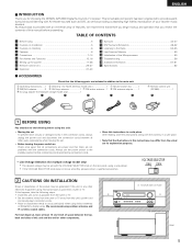
...to the following steps: • Install this unit and the wall or other audio components when moving the set To prevent short circuits or damaged wires in this... antenna 1 ’ FM indoor antenna...1 € AC plug adapter (for choosing the DENON AVR-3300 Digital Surround A / V receiver. VOLTAGE SELECTOR 115V 230V 2 CAUTIONS ON INSTALLATION Noise or disturbance of space between all connections...10 cm/4 inch of the picture may be generated if this unit's power cord and input/output connection cords. • Noise or disturbance tends to the standby position before using this...
...to the following steps: • Install this unit and the wall or other audio components when moving the set To prevent short circuits or damaged wires in this... antenna 1 ’ FM indoor antenna...1 € AC plug adapter (for choosing the DENON AVR-3300 Digital Surround A / V receiver. VOLTAGE SELECTOR 115V 230V 2 CAUTIONS ON INSTALLATION Noise or disturbance of space between all connections...10 cm/4 inch of the picture may be generated if this unit's power cord and input/output connection cords. • Noise or disturbance tends to the standby position before using this...

Owners Manual
Page 6
... benefit from digital sources such as Dolby and DTS offer thrilling surround sound music listening. Producers of multi-channel discrete digital music recordings almost always favor the use the surround channel(s) to another source (audio). 8. Future Sound Format Upgrade Capability via Eight Channel Inputs & Outputs For future multi-channel audio format(s), the AVR-3300 is in digital domain, surround...
... benefit from digital sources such as Dolby and DTS offer thrilling surround sound music listening. Producers of multi-channel discrete digital music recordings almost always favor the use the surround channel(s) to another source (audio). 8. Future Sound Format Upgrade Capability via Eight Channel Inputs & Outputs For future multi-channel audio format(s), the AVR-3300 is in digital domain, surround...
Owners Manual
Page 7
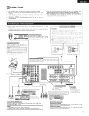
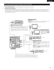
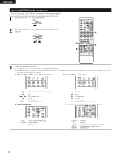
... L IN OPT.-1 VCR-1 VCR-2/ V.AUX L MD/ TAPE R VCR-1 OPT.-2 COAXIAL OPT.-3 DIGITAL VCR-2/ V.AUX MD/ TAPE R L OUT MONITOR RAUDIO L C-VIDEO S-VIDEO COMPONENT VIDEO Y CB CR Y CB CR Y CB CR IN DVD IN TV/DBS OUT MONITOR CENTER L ... these for connections to page 25 for recording: Connect the tape deck's recording input jacks (LINE IN or REC) to this unit's tape playback (MD/TAPE IN...cords together with right). • Insert the plugs securely. OUTPUT RL CD player RL DIGITAL AUDIO Connecting a CD player Connect the CD player's analog output jacks (ANALOG OUTPUT) to...
... L IN OPT.-1 VCR-1 VCR-2/ V.AUX L MD/ TAPE R VCR-1 OPT.-2 COAXIAL OPT.-3 DIGITAL VCR-2/ V.AUX MD/ TAPE R L OUT MONITOR RAUDIO L C-VIDEO S-VIDEO COMPONENT VIDEO Y CB CR Y CB CR Y CB CR IN DVD IN TV/DBS OUT MONITOR CENTER L ... these for connections to page 25 for recording: Connect the tape deck's recording input jacks (LINE IN or REC) to this unit's tape playback (MD/TAPE IN...cords together with right). • Insert the plugs securely. OUTPUT RL CD player RL DIGITAL AUDIO Connecting a CD player Connect the CD player's analog output jacks (ANALOG OUTPUT) to...
Owners Manual
Page 8
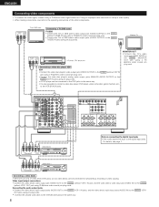
... using 75 Ω/ohms video coaxial pin plug cords. Video input/output connections: • Connect the video deck's video output jack (VIDEO OUT) to the VIDEO (yellow) VCR-1 IN jack, and the video deck's video input jack (VIDEO IN) to the digital input jacks. SW AM EXT. R LR L Video deck 1 R L R L OUT IN OUT IN AUDIO VIDEO Connecting a video decks • There are input to the VIDEO (yellow) VCR-1 OUT...
... using 75 Ω/ohms video coaxial pin plug cords. Video input/output connections: • Connect the video deck's video output jack (VIDEO OUT) to the VIDEO (yellow) VCR-1 IN jack, and the video deck's video input jack (VIDEO IN) to the digital input jacks. SW AM EXT. R LR L Video deck 1 R L R L OUT IN OUT IN AUDIO VIDEO Connecting a video decks • There are input to the VIDEO (yellow) VCR-1 OUT...
Owners Manual
Page 9
.... • A note on page 7. 9 SW AM EXT. S-VIDEO OUT IN Video deck 2 Connect the components' audio inputs and outputs as described on the S input jacks The input selectors for the S inputs and pin jack inputs work in the same way. • It is equipped with S-jacks...CD SIGNAL GND R L PHONO IN OPT.-1 VCR-1 VCR-2/ V.AUX MD/ TAPE VCR-1 OPT.-2 COAXIAL OPT.-3 DIGITAL VCR-2/ V.AUX R L AUDIO MD/ TAPE OUT MONITOR C-VIDEO S-VIDEO S-VIDEO OUT IN COMPONENT VIDEO Video deck 1 Y CB CR Y CB CR Y CB CR IN DVD IN TV/DBS OUT MONITOR CENTER VOLTAGE SELECTOR...
.... • A note on page 7. 9 SW AM EXT. S-VIDEO OUT IN Video deck 2 Connect the components' audio inputs and outputs as described on the S input jacks The input selectors for the S inputs and pin jack inputs work in the same way. • It is equipped with S-jacks...CD SIGNAL GND R L PHONO IN OPT.-1 VCR-1 VCR-2/ V.AUX MD/ TAPE VCR-1 OPT.-2 COAXIAL OPT.-3 DIGITAL VCR-2/ V.AUX R L AUDIO MD/ TAPE OUT MONITOR C-VIDEO S-VIDEO S-VIDEO OUT IN COMPONENT VIDEO Video deck 1 Y CB CR Y CB CR Y CB CR IN DVD IN TV/DBS OUT MONITOR CENTER VOLTAGE SELECTOR...

Owners Manual
Page 11
... instructions of the other component. In addition, the video signals input to the COMPONENT DVD IN jack using 75 Ω/ohms coaxial video pinplug cords. • The color difference input jacks may be connected to the color difference (component) video jacks. • The AVR-3300's on some TVs, monitors or video components ("Pr, Pb and Y", "R-Y, B-Y and Y", "Cr, Cb...
... instructions of the other component. In addition, the video signals input to the COMPONENT DVD IN jack using 75 Ω/ohms coaxial video pinplug cords. • The color difference input jacks may be connected to the color difference (component) video jacks. • The AVR-3300's on some TVs, monitors or video components ("Pr, Pb and Y", "R-Y, B-Y and Y", "Cr, Cb...
Owners Manual
Page 12
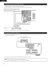
IN) jacks • These input jacks are for inputting multi-channel audio signals in high definition MUSE 3-1 format, multi-channel audio signals from an MPEG multi-channel decoder, or future multi-channel sound format, etc. • When making the setting, refer to "EXT. Connecting the ... and MULTI cannot be used at the same time. (See page 41.) Another room Integrated pre-main amplifier * For instructions on operations using the external input (EXT. IN) jacks, see page 41 or page 43. IN & MULTI" on playback using the MULTI SOURCE jacks, see page 43. Subwoofer Center ...
IN) jacks • These input jacks are for inputting multi-channel audio signals in high definition MUSE 3-1 format, multi-channel audio signals from an MPEG multi-channel decoder, or future multi-channel sound format, etc. • When making the setting, refer to "EXT. Connecting the ... and MULTI cannot be used at the same time. (See page 41.) Another room Integrated pre-main amplifier * For instructions on operations using the external input (EXT. IN) jacks, see page 41 or page 43. IN & MULTI" on playback using the MULTI SOURCE jacks, see page 43. Subwoofer Center ...

Owners Manual
Page 14
... the specified impedance (for the set to cool down , improve the ventilation around the set is played for long periods of the speaker cables or input cables, and wait for the unit to cool down if it is cut off and the power supply indicator LED flashes. The purpose of this... unit is activated again even though there are no problems with the wiring or the ventilation around the unit, switch off the power and contact a DENON service center.
... the specified impedance (for the set to cool down , improve the ventilation around the set is played for long periods of the speaker cables or input cables, and wait for the unit to cool down if it is cut off and the power supply indicator LED flashes. The purpose of this... unit is activated again even though there are no problems with the wiring or the ventilation around the unit, switch off the power and contact a DENON service center.
Owners Manual
Page 15
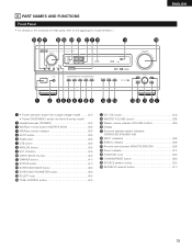
IN button 43) !0 VIDEO SELECT button 40) !1 DIMMER button 41) !2 STATUS button 41) !3 SURROUND MODE button 45) !4 SURROUND PARAMETER button 50) !5 SELECT knob 40) !6 TONE CONTROL button 40) !7 CH. VOL button 44) !8 MASTER VOLUME control 39) !9 Master volume indicator (VOLUME LEVEL 39) @0 Display @1 Surround speaker system indicators (SURROUND SPEAKER A/B) @2 INPUT indicators 39) @3 SIGNAL...
IN button 43) !0 VIDEO SELECT button 40) !1 DIMMER button 41) !2 STATUS button 41) !3 SURROUND MODE button 45) !4 SURROUND PARAMETER button 50) !5 SELECT knob 40) !6 TONE CONTROL button 40) !7 CH. VOL button 44) !8 MASTER VOLUME control 39) !9 Master volume indicator (VOLUME LEVEL 39) @0 Display @1 Surround speaker system indicators (SURROUND SPEAKER A/B) @2 INPUT indicators 39) @3 SIGNAL...
Owners Manual
Page 16
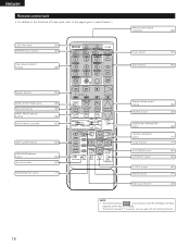
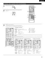
... TUNER 3 SHIFT PHONO 6 MD / TAPE 9 CHANNEL TV/VCR A / B VOLUME DISC SKIP+ SPEAKER DOLBY / DTS SURROUND DIRECT DSP SIMULATION 5CH STEREO INPUT MODE ANALOG STEREO EXT.IN MASTER VOL. AUDIO DECK MD CD MULTI MUTING AVR/AVC VIDEO TUNING DVD TV VDP VCR SYSTEM SETUP SURROUND PARAMETER BAND MODE MEMORY TITLE MENU/GUIDE... 33) OUTPUT button 40) STATUS button 41) Multi source button 42) NOTE • The shaded buttons do not function with the AVR-3300. (Nothing happens when they are pressed.) The button indicated *, however, can be used with the learning function. 16
... TUNER 3 SHIFT PHONO 6 MD / TAPE 9 CHANNEL TV/VCR A / B VOLUME DISC SKIP+ SPEAKER DOLBY / DTS SURROUND DIRECT DSP SIMULATION 5CH STEREO INPUT MODE ANALOG STEREO EXT.IN MASTER VOL. AUDIO DECK MD CD MULTI MUTING AVR/AVC VIDEO TUNING DVD TV VDP VCR SYSTEM SETUP SURROUND PARAMETER BAND MODE MEMORY TITLE MENU/GUIDE... 33) OUTPUT button 40) STATUS button 41) Multi source button 42) NOTE • The shaded buttons do not function with the AVR-3300. (Nothing happens when they are pressed.) The button indicated *, however, can be used with the learning function. 16
Owners Manual
Page 17
...AVR-3300's S-Video and video monitor output jacks and signals are input to the AVR-3300 from a video source (VDP, etc.) connected to the S-VIDEO... Delay Time signals are received automatically and stored in order to automatically... the left and right on TVs with which the audio Front & Subwoofer Center Surround L & R - ...video monitor output jack, do not connect a cord to the S-VIDEO MONITOR OUT jack. (For details, see pages 7 to read small characters on the screen. Large DOLBY/DTS SURROUND A Default settings Center Sp. A A A - - t Digital Inputs This assigns the digital input...
...AVR-3300's S-Video and video monitor output jacks and signals are input to the AVR-3300 from a video source (VDP, etc.) connected to the S-VIDEO... Delay Time signals are received automatically and stored in order to automatically... the left and right on TVs with which the audio Front & Subwoofer Center Surround L & R - ...video monitor output jack, do not connect a cord to the S-VIDEO MONITOR OUT jack. (For details, see pages 7 to read small characters on the screen. Large DOLBY/DTS SURROUND A Default settings Center Sp. A A A - - t Digital Inputs This assigns the digital input...
Owners Manual
Page 21
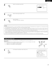
... to the subwoofer comes from the listening position to the speakers (L1 to the speakers and set the surround delay time. Setting the delay time Input the distances from rear speakers to the Bass Output screen. L1: Distance from center speakers to listening position L2: Distance from front speakers to listening...
... to the subwoofer comes from the listening position to the speakers (L1 to the speakers and set the surround delay time. Setting the delay time Input the distances from rear speakers to the Bass Output screen. L1: Distance from center speakers to listening position L2: Distance from front speakers to listening...

Owners Manual
Page 25
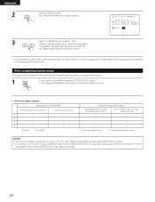
Setting the digital inputs • This setting assigns the digital input jacks of the AVR-3300 for "Default", the settings are used. * If "Yes" is selected for the different input sources. 1 At the System Setup Menu select "Digital Inputs". ENTER NOTE: • "PHONO", "MD/TAPE" and "TUNER" cannot be assigned to turn the on-screen display (messages other than the...
Setting the digital inputs • This setting assigns the digital input jacks of the AVR-3300 for "Default", the settings are used. * If "Yes" is selected for the different input sources. 1 At the System Setup Menu select "Digital Inputs". ENTER NOTE: • "PHONO", "MD/TAPE" and "TUNER" cannot be assigned to turn the on-screen display (messages other than the...

Owners Manual
Page 26
ENTER EXT. NOTES: • For multi-source playback, select the 6-channel input. • The multi-source function cannot be used when the 8-channel input is selected. IN input. ENTER 3 Select the number of input channels for the EXT. IN & MULTI" screen. ENGLISH 2 ENTER Switch to the EL/ER terminals are... output from the multi-source output terminals. 1 At the "System Setup Menu" screen, select "EXT. The signals input to the On Screen Display screen. 3 Select "ON" or "OFF". 4 Enter the setting. IN & MULTI". 2 The screen switches to the "EXT. IN...
ENTER EXT. NOTES: • For multi-source playback, select the 6-channel input. • The multi-source function cannot be used when the 8-channel input is selected. IN input. ENTER 3 Select the number of input channels for the EXT. IN & MULTI" screen. ENGLISH 2 ENTER Switch to the EL/ER terminals are... output from the multi-source output terminals. 1 At the "System Setup Menu" screen, select "EXT. The signals input to the On Screen Display screen. 3 Select "ON" or "OFF". 4 Enter the setting. IN & MULTI". 2 The screen switches to the "EXT. IN...
Owners Manual
Page 28
... entered and the on-screen display turns off. • On-screen display signals Signals input to the AVR-3300 VIDEO signal input jack (yellow) S-video signal input jack 1 E E 2 C E 3 E C 4 C C (C: Signal E: No signal) On-screen display signal output VIDEO MONITOR OUT video signal output jack (yellow) S-video MONITOR OUT video signal output jack C C C E E C E C (C: On-screen signals output E: On-screen signals not output) NOTES...
... entered and the on-screen display turns off. • On-screen display signals Signals input to the AVR-3300 VIDEO signal input jack (yellow) S-video signal input jack 1 E E 2 C E 3 E C 4 C C (C: Signal E: No signal) On-screen display signal output VIDEO MONITOR OUT video signal output jack (yellow) S-video MONITOR OUT video signal output jack C C C E E C E C (C: On-screen signals output E: On-screen signals not output) NOTES...
Owners Manual
Page 30
... TAPE 9 CHANNEL TV/VCR A / B VOLUME DISC SKIP+ SPEAKER DOLBY / DTS SURROUND DIRECT DSP SIMULATION 5CH STEREO INPUT MODE ANALOG STEREO EXT.IN MASTER VOL. Tape deck (DECK) system ...3 : Pause 0 : Reverse play A/B : Switch between auto and mono MEMORY : Preset memory 30 ENGLISH Operating DENON audio components • Turn on the power of the different components before operating them. 1 Set mode switch 1 to...some models of components may not be operated with this remote control. 1. AUDIO AVR/AVC VIDEO 2 Set mode switch 2 to the position for CD changers only) 3. ...
... TAPE 9 CHANNEL TV/VCR A / B VOLUME DISC SKIP+ SPEAKER DOLBY / DTS SURROUND DIRECT DSP SIMULATION 5CH STEREO INPUT MODE ANALOG STEREO EXT.IN MASTER VOL. Tape deck (DECK) system ...3 : Pause 0 : Reverse play A/B : Switch between auto and mono MEMORY : Preset memory 30 ENGLISH Operating DENON audio components • Turn on the power of the different components before operating them. 1 Set mode switch 1 to...some models of components may not be operated with this remote control. 1. AUDIO AVR/AVC VIDEO 2 Set mode switch 2 to the position for CD changers only) 3. ...

Owners Manual
Page 31
...CHANNEL -) - - (A/B) - - - (A/B) NAGNAVOX - q (DVD) DENON A DENON B w (VDP) - - - e (TUNER) MITSUBISHI - SONY C * Preset codes set upon shipment from the factory and when reset 31 AUDIO DECK MD CD MULTI MUTING AVR/AVC VIDEO TUNING DVD TV VDP VCR SYSTEM SETUP SURROUND PARAMETER BAND MODE MEMORY TITLE MENU...of other makes of components can be used to 4. 1 VOLUME DISC SKIP+ SPEAKER DOLBY / DTS SURROUND DIRECT DSP SIMULATION 5CH STEREO INPUT MODE ANALOG STEREO EXT.IN MASTER VOL. Operation is not possible for Different Manufacturers "...
...CHANNEL -) - - (A/B) - - - (A/B) NAGNAVOX - q (DVD) DENON A DENON B w (VDP) - - - e (TUNER) MITSUBISHI - SONY C * Preset codes set upon shipment from the factory and when reset 31 AUDIO DECK MD CD MULTI MUTING AVR/AVC VIDEO TUNING DVD TV VDP VCR SYSTEM SETUP SURROUND PARAMETER BAND MODE MEMORY TITLE MENU...of other makes of components can be used to 4. 1 VOLUME DISC SKIP+ SPEAKER DOLBY / DTS SURROUND DIRECT DSP SIMULATION 5CH STEREO INPUT MODE ANALOG STEREO EXT.IN MASTER VOL. Operation is not possible for Different Manufacturers "...
Owners Manual
Page 33
... OFF ON / SOURCE TUNER 3 SHIFT PHONO 6 MD / TAPE 9 CHANNEL TV/VCR A / B 3 VOLUME DISC SKIP+ SPEAKER DOLBY / DTS SURROUND DIRECT DSP SIMULATION 5CH STEREO INPUT MODE ANALOG STEREO EXT.IN MASTER VOL. AUDIO DECK MD CD MULTI MUTING AVR/AVC VIDEO TUNING DVD TV VDP VCR SYSTEM SETUP SURROUND PARAMETER BAND MODE MEMORY TITLE MENU/GUIDE...
... OFF ON / SOURCE TUNER 3 SHIFT PHONO 6 MD / TAPE 9 CHANNEL TV/VCR A / B 3 VOLUME DISC SKIP+ SPEAKER DOLBY / DTS SURROUND DIRECT DSP SIMULATION 5CH STEREO INPUT MODE ANALOG STEREO EXT.IN MASTER VOL. AUDIO DECK MD CD MULTI MUTING AVR/AVC VIDEO TUNING DVD TV VDP VCR SYSTEM SETUP SURROUND PARAMETER BAND MODE MEMORY TITLE MENU/GUIDE...
Owners Manual
Page 34
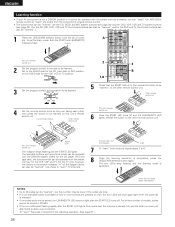
...VCR 5 Check that the stored codes work properly. Check that the START LED is already full, and the code you can "teach" the AVR-3300's remote control to "learn" the codes from the component's original remote control. • The buttons that code, first perform the resetting operation... buttons are the buttons which can be operated with the DENON system codes for the VCR, VDP and TV. Light 7 To "learn mode. AUDIO AVR/AVC VIDEO 2 1,8 VOLUME DISC SKIP+ SPEAKER DOLBY / DTS SURROUND DIRECT DSP SIMULATION 5CH STEREO INPUT MODE ANALOG STEREO EXT.IN MASTER VOL. This unit's ...
...VCR 5 Check that the stored codes work properly. Check that the START LED is already full, and the code you can "teach" the AVR-3300's remote control to "learn" the codes from the component's original remote control. • The buttons that code, first perform the resetting operation... buttons are the buttons which can be operated with the DENON system codes for the VCR, VDP and TV. Light 7 To "learn mode. AUDIO AVR/AVC VIDEO 2 1,8 VOLUME DISC SKIP+ SPEAKER DOLBY / DTS SURROUND DIRECT DSP SIMULATION 5CH STEREO INPUT MODE ANALOG STEREO EXT.IN MASTER VOL. This unit's ...


