Literature/Product Sheet
Page 1
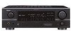
... software.. Video Game 7. Mono Movie 3. Black version is too strong. s Auto Setup with Microphone The AVR-1707 is equipped with a total of 7 power amps including 2 for the Surround Back channel... Equalizer The sound from 10 Hz to the AVR-1707 iPod (*1) playback can also be enjoyed through the AVR-1707 when the ASD-1R, Denon's original Control Dock for iPod (sold separately),...1R Control Dock for iPod® (option): Supports iPod playback when connected to 100 kHz. A/V Receiver AVR-1707 DTS-ES Discrete 6.1 and Dolby Digital EX with Power Amps for 7 Channels Audio section s Fully...
... software.. Video Game 7. Mono Movie 3. Black version is too strong. s Auto Setup with Microphone The AVR-1707 is equipped with a total of 7 power amps including 2 for the Surround Back channel... Equalizer The sound from 10 Hz to the AVR-1707 iPod (*1) playback can also be enjoyed through the AVR-1707 when the ASD-1R, Denon's original Control Dock for iPod (sold separately),...1R Control Dock for iPod® (option): Supports iPod playback when connected to 100 kHz. A/V Receiver AVR-1707 DTS-ES Discrete 6.1 and Dolby Digital EX with Power Amps for 7 Channels Audio section s Fully...
Owners Manual - English
Page 4
... mode 23 Selecting the DTS NEO:6 mode 24 Selecting the NEURAL SURROUND mode 24 Surround modes and parameters 25 ~ 27 Using the DENON original surround modes Types of surround modes and their features 28 Selecting the DSP surround simulation 29 Setting the tone control 30 Adjusting the...high fidelity reproduction of the remote control unit 3 Part names and functions Front panel 4 Display 4 Rear panel 5 Remote control unit 5, 6 Easy Setup Procedure Easy to music in the Browse mode 34 Viewing still pictures and videos (only for choosing the DENON AVR-1707 AV Surround Receiver.
... mode 23 Selecting the DTS NEO:6 mode 24 Selecting the NEURAL SURROUND mode 24 Surround modes and parameters 25 ~ 27 Using the DENON original surround modes Types of surround modes and their features 28 Selecting the DSP surround simulation 29 Setting the tone control 30 Adjusting the...high fidelity reproduction of the remote control unit 3 Part names and functions Front panel 4 Display 4 Rear panel 5 Remote control unit 5, 6 Easy Setup Procedure Easy to music in the Browse mode 34 Viewing still pictures and videos (only for choosing the DENON AVR-1707 AV Surround Receiver.
Owners Manual - English
Page 5
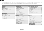
... the Speaker Configuration 45, 46 Setting the Subwoofer Mode Setup 46 Setting the Distance 46, 47 Setting the Crossover Frequency 47 Setting the Test Tone 47 Operating the remote control unit Operating DENON audio components 48 Setting the preset memory function 48 Operating ... America model only 1 e Service station list 1 r Remote control unit (RC-1048 1 t R6P/AA batteries 2 y AM loop antenna 1 u FM indoor antenna 1 i Setup microphone (DM-S205) (Approx. 23-5/8 ft / 6 m) ..........1 r t y u i Pay attention to the following parts are not problems with the warranty card in a ...
... the Speaker Configuration 45, 46 Setting the Subwoofer Mode Setup 46 Setting the Distance 46, 47 Setting the Crossover Frequency 47 Setting the Test Tone 47 Operating the remote control unit Operating DENON audio components 48 Setting the preset memory function 48 Operating ... America model only 1 e Service station list 1 r Remote control unit (RC-1048 1 t R6P/AA batteries 2 y AM loop antenna 1 u FM indoor antenna 1 i Setup microphone (DM-S205) (Approx. 23-5/8 ft / 6 m) ..........1 r t y u i Pay attention to the following parts are not problems with the warranty card in a ...

Owners Manual - English
Page 7
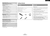
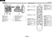
... channel indicator Lights when the preset channel is displayed in the AUTO tuning mode. o TUNED indicator This lights when an FM/AM broadcast has been received. 4 ENGLISH Front panel @4 @0 !8 #0 @9 @8 @7 @6 @5 @3 @2 @1 !9 !7 ENGLISH !6 Cursor buttons (D, H 22, 40) !7 MASTER VOLUME control knob 19) !8 TUNING buttons 31) !9 STATUS button 20) @0 DIMMER button 20)...Started @4 INPUT mode indicators 19) @5 SIGNAL indicators 22) @6 BAND button 31) @7 EXT. u STEREO indicator This lights when an FM stereo broadcast has been received. The Setup item number is displayed at w.
... channel indicator Lights when the preset channel is displayed in the AUTO tuning mode. o TUNED indicator This lights when an FM/AM broadcast has been received. 4 ENGLISH Front panel @4 @0 !8 #0 @9 @8 @7 @6 @5 @3 @2 @1 !9 !7 ENGLISH !6 Cursor buttons (D, H 22, 40) !7 MASTER VOLUME control knob 19) !8 TUNING buttons 31) !9 STATUS button 20) @0 DIMMER button 20)...Started @4 INPUT mode indicators 19) @5 SIGNAL indicators 22) @6 BAND button 31) @7 EXT. u STEREO indicator This lights when an FM stereo broadcast has been received. The Setup item number is displayed at w.
Owners Manual - English
Page 8
.../S-VIDEO terminals 9) !0 DOCK CONTROL jack 17) !1 AUDIO IN terminals 9) !2 XM terminal 16) !3 ANTENNA terminals 16) !4 REMOTE CONTROL jacks 17) System buttons 50, 51) VIDEO SELECT/SETUP button 33, 50) Cursor buttons ···(11, 22, 50) DISPLAY button 50) DIMMER/MENU button 20, 50) [ Front ] Getting Started Remote control signal...
.../S-VIDEO terminals 9) !0 DOCK CONTROL jack 17) !1 AUDIO IN terminals 9) !2 XM terminal 16) !3 ANTENNA terminals 16) !4 REMOTE CONTROL jacks 17) System buttons 50, 51) VIDEO SELECT/SETUP button 33, 50) Cursor buttons ···(11, 22, 50) DISPLAY button 50) DIMMER/MENU button 20, 50) [ Front ] Getting Started Remote control signal...

Owners Manual - English
Page 9
Getting Started ZONE2 buttons 36) Input source selector/ Number buttons 19, 51) Tuner system/System buttons 31, 51) TEST TONE/DISPLAY button 47, 51) Cursor buttons ···(11, 22, 51) [ Rear ] MAIN buttons 36) SURROUND MODE buttons 21, 29) SYSTEM SETUP/SETUP button 40, 51) SURROUND PARAMETER/ AUDIO button 22, 51) ENTER button 30, 51) INPUT MODE/RETURN button 19, 51) NOTE: • If buttons on the front or rear are pressed strongly, the button on the opposite side will be activated too. 6 ENGLISH ENGLISH Getting Started
Getting Started ZONE2 buttons 36) Input source selector/ Number buttons 19, 51) Tuner system/System buttons 31, 51) TEST TONE/DISPLAY button 47, 51) Cursor buttons ···(11, 22, 51) [ Rear ] MAIN buttons 36) SURROUND MODE buttons 21, 29) SYSTEM SETUP/SETUP button 40, 51) SURROUND PARAMETER/ AUDIO button 22, 51) ENTER button 30, 51) INPUT MODE/RETURN button 19, 51) NOTE: • If buttons on the front or rear are pressed strongly, the button on the opposite side will be activated too. 6 ENGLISH ENGLISH Getting Started
Owners Manual - English
Page 10
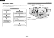
Connecting a microphone ( page 10). The measurement of the measurement result. ENGLISH Easy Setup Procedure • This section contains the basic steps necessary to configure the AVR-1707 according to the AVR-1707. Connect the DVD player to your listening room environment and the source equipment and loudspeakers... you are using. • To set the sound field manually ( page 45). Connect the AVR-1707's monitor output terminal to setup flow Speaker layout [Basic layout] Example of the screen as flush with the front of basic layout with eight speakers...
Connecting a microphone ( page 10). The measurement of the measurement result. ENGLISH Easy Setup Procedure • This section contains the basic steps necessary to configure the AVR-1707 according to the AVR-1707. Connect the DVD player to your listening room environment and the source equipment and loudspeakers... you are using. • To set the sound field manually ( page 45). Connect the AVR-1707's monitor output terminal to setup flow Speaker layout [Basic layout] Example of the screen as flush with the front of basic layout with eight speakers...
Owners Manual - English
Page 11
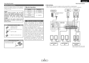
... the temperature to ten speakers can be connected for subwoofer with built-in amplifier. ENGLISH Easy Setup Procedure ¢ Connections • With the AVR-1707, up to rise, activating the protection circuit. Tighten by turning counterclockwise. NOTE: When making ...cable. 3. If this , plug the power cord back in and turn the unit's power back on. Easy Setup Procedure Speaker connections Connect the speaker terminals with the speakers making sure that none of the individual conductors of the .... If the protection circuit is cut off the power and contact a DENON service center.
... the temperature to ten speakers can be connected for subwoofer with built-in amplifier. ENGLISH Easy Setup Procedure ¢ Connections • With the AVR-1707, up to rise, activating the protection circuit. Tighten by turning counterclockwise. NOTE: When making ...cable. 3. If this , plug the power cord back in and turn the unit's power back on. Easy Setup Procedure Speaker connections Connect the speaker terminals with the speakers making sure that none of the individual conductors of the .... If the protection circuit is cut off the power and contact a DENON service center.
Owners Manual - English
Page 12
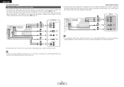
...Assignment ( page 41). DVD player H COMPONENT VIDEO OUT Y PB PR G S VIDEO OUT F VIDEO OUT D OPTICAL OUT A AUDIO OUT L L L R R R Easy Setup Procedure • For best picture quality (especially with gray arrows. • Connect a non-DVD video disc player (such as a laser disc, VCD/SVCD, or future...8226; The component video input and/or output terminals may be assigned. ENGLISH Easy Setup Procedure Connecting a DVD player and monitor • To connect the video output from the DVD player to the AVR-1707, you can choose from the DVD player, you only need to choose one ...
...Assignment ( page 41). DVD player H COMPONENT VIDEO OUT Y PB PR G S VIDEO OUT F VIDEO OUT D OPTICAL OUT A AUDIO OUT L L L R R R Easy Setup Procedure • For best picture quality (especially with gray arrows. • Connect a non-DVD video disc player (such as a laser disc, VCD/SVCD, or future...8226; The component video input and/or output terminals may be assigned. ENGLISH Easy Setup Procedure Connecting a DVD player and monitor • To connect the video output from the DVD player to the AVR-1707, you can choose from the DVD player, you only need to choose one ...
Owners Manual - English
Page 13
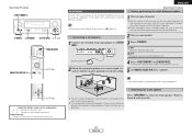
... . ¢ ON: The power indicator lights red. £ OFF: The power turns off if your subwoofer. Easy Setup Procedure D H F G [ON/SOURCE] [MODE SELECTOR 1] D H F G ENGLISH Easy Setup Procedure Auto Setup w Before performing the Auto Setup procedure The AVR-1707's auto setup use the attached microphone to measure properly if there are no obstacles. q Connecting a microphone 1 Connect the attached...
... . ¢ ON: The power indicator lights red. £ OFF: The power turns off if your subwoofer. Easy Setup Procedure D H F G [ON/SOURCE] [MODE SELECTOR 1] D H F G ENGLISH Easy Setup Procedure Auto Setup w Before performing the Auto Setup procedure The AVR-1707's auto setup use the attached microphone to measure properly if there are no obstacles. q Connecting a microphone 1 Connect the attached...
Owners Manual - English
Page 14
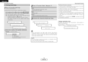
All parameters are stored. Cancel: Cancel the checked measurement values. 3 Disconnect the setup mic to select "Store", then press F. Measure:FL Measurement of each channel is set at "Setting the Power Amplifier Assignment" ( page 43). After each channel ... speaker is measured twice. 2: Not displayed when "ZONE2" is measured, "Calculating" appears. The display switches to the speaker check display automatically. 2 Press D H to finish Auto Setup. Store: Store the checked measurement values. Retry: Measure again. ENGLISH Easy...
All parameters are stored. Cancel: Cancel the checked measurement values. 3 Disconnect the setup mic to select "Store", then press F. Measure:FL Measurement of each channel is set at "Setting the Power Amplifier Assignment" ( page 43). After each channel ... speaker is measured twice. 2: Not displayed when "ZONE2" is measured, "Calculating" appears. The display switches to the speaker check display automatically. 2 Press D H to finish Auto Setup. Store: Store the checked measurement values. Retry: Measure again. ENGLISH Easy...
Owners Manual - English
Page 15
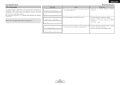
Easy Setup Procedure Error messages An error message is displayed if the measurements could not be completed automatically due to select the items, then press F. Press D H to the speaker layout, the measuring environment, etc. Be sure to turn off the AVR-1707's power before checking the speaker connections. Please check the following matters, reset the pertinent items, and measure again. Example Caution:SP None F L Caution :Phase F L / R C a u t i o n Overload
Easy Setup Procedure Error messages An error message is displayed if the measurements could not be completed automatically due to select the items, then press F. Press D H to the speaker layout, the measuring environment, etc. Be sure to turn off the AVR-1707's power before checking the speaker connections. Please check the following matters, reset the pertinent items, and measure again. Example Caution:SP None F L Caution :Phase F L / R C a u t i o n Overload

Owners Manual - English
Page 29
... DOLBY DIGITAL EX DOLBY DIGITAL EX (With Flag) (With no Flag) DOLBY DIGITAL (5.1ch) E E E E E E 4 E C E C E C E E E E E E C E C E 4 E C E E E E E E E E E E E E E E E E E E E E E E E E E E E E E E E E E E C C 4 4 C C C C E E E E E E E E E E E E E E E E NOTE : *1: This mode is not available when the Surround Back speaker setup is set to "None". *2: This mode is not available when the Surround Back speaker...
... DOLBY DIGITAL EX DOLBY DIGITAL EX (With Flag) (With no Flag) DOLBY DIGITAL (5.1ch) E E E E E E 4 E C E C E C E E E E E E C E C E 4 E C E E E E E E E E E E E E E E E E E E E E E E E E E E E E E E E E E E C C 4 4 C C C C E E E E E E E E E E E E E E E E NOTE : *1: This mode is not available when the Surround Back speaker setup is set to "None". *2: This mode is not available when the Surround Back speaker...

Owners Manual - English
Page 30
...(With Flag) (With no Flag) DOLBY DIGITAL (5.1ch) C C C C C C C C C *1 C C C C C C C C C C C C C C C C C C C C C C C C C C C C C C C C C C C C C C C C C C C C C C C C C C C C C C C C C C C C C C C 4 4 C 4 : Mode selectable in default status C : Selectable mode E : Non-selectable mode C C C C NOTE : *1: If the Surround Back speaker setup is set to "None", then "5CH STEREO" is displayed. C C DOLBY DIGITAL (3, 4, 5ch) C C C C C C C C C Basic Operation DOLBY DIGITAL (2ch) DVD-AUDIO DVD-Audio DVD-Audio (multi...
...(With Flag) (With no Flag) DOLBY DIGITAL (5.1ch) C C C C C C C C C *1 C C C C C C C C C C C C C C C C C C C C C C C C C C C C C C C C C C C C C C C C C C C C C C C C C C C C C C C C C C C C C C C 4 4 C 4 : Mode selectable in default status C : Selectable mode E : Non-selectable mode C C C C NOTE : *1: If the Surround Back speaker setup is set to "None", then "5CH STEREO" is displayed. C C DOLBY DIGITAL (3, 4, 5ch) C C C C C C C C C Basic Operation DOLBY DIGITAL (2ch) DVD-AUDIO DVD-Audio DVD-Audio (multi...
Owners Manual - English
Page 41
...Front Sp. Small / 2sp Page 45, 46 7 8 ~ 15 Subwoofer Mode Setup Distance mode Select the method of playback of the various speakers so that was input to any input terminals on the AVR-1707 and play them. 6 ~ 8 9 ~ 12 13 Component In Assignment mode Video...0 dB 0 dB 2. DVD Comp 1 iPod Function = OFF TV Comp 2 VCR Comp 3 ON 0 ms 14 EXT. Speaker Setup Speaker Setup Item No. Subwoofer Surround Sp. ENGLISH Advanced Setup - Items 1 ~ 6 Speaker Configuration mode Automatically set the output component and properties for the various channels according to the combination of the...
...Front Sp. Small / 2sp Page 45, 46 7 8 ~ 15 Subwoofer Mode Setup Distance mode Select the method of playback of the various speakers so that was input to any input terminals on the AVR-1707 and play them. 6 ~ 8 9 ~ 12 13 Component In Assignment mode Video...0 dB 0 dB 2. DVD Comp 1 iPod Function = OFF TV Comp 2 VCR Comp 3 ON 0 ms 14 EXT. Speaker Setup Speaker Setup Item No. Subwoofer Surround Sp. ENGLISH Advanced Setup - Items 1 ~ 6 Speaker Configuration mode Automatically set the output component and properties for the various channels according to the combination of the...

Owners Manual - English
Page 42
... to the front channel ("Front A" or "Front B") for the input signal. Part 1 Page 43 44 44 Auto Surround Mode = ON 45 39 ENGLISH Option Setup Option Setup Item No. 1 Power Amp Assignment mode Items To suit your preference, a surround back channel's power amplifier can be assigned to store the surround mode last...-amp playback, ZONE2. 2 ~ 4 Volume Control mode This sets the volume level of output. Back Vol.Limit = OFF P. On Lev. = LAST Mute Lev. = FULL OFF Advanced Setup - Part 1 3. Default settings S. ENGLISH Advanced...
... to the front channel ("Front A" or "Front B") for the input signal. Part 1 Page 43 44 44 Auto Surround Mode = ON 45 39 ENGLISH Option Setup Option Setup Item No. 1 Power Amp Assignment mode Items To suit your preference, a surround back channel's power amplifier can be assigned to store the surround mode last...-amp playback, ZONE2. 2 ~ 4 Volume Control mode This sets the volume level of output. Back Vol.Limit = OFF P. On Lev. = LAST Mute Lev. = FULL OFF Advanced Setup - Part 1 3. Default settings S. ENGLISH Advanced...
Owners Manual - English
Page 43
... Item No. To cancel the system setup mode, press SYSTEM SETUP again. 1 *System Setup 2 Speaker Setup 3 1 Front L a r g e 5 40 ENGLISH Part 1 About the front display The AVR-1707 is equipped with an alpha numeric front panel display that can also be used to... selected line Current setting Press F to execute. 17 T.Tone Yes< Currently selected line 5 Press SYSTEM SETUP to check and adjust settings. Advanced Setup - Part 1 SYSTEM SETUP ENTER F G, ENTER D H D H F G SYSTEM SETUP ENTER D H F G About the button names in this unit ( page 38, 39). Some representative...
... Item No. To cancel the system setup mode, press SYSTEM SETUP again. 1 *System Setup 2 Speaker Setup 3 1 Front L a r g e 5 40 ENGLISH Part 1 About the front display The AVR-1707 is equipped with an alpha numeric front panel display that can also be used to... selected line Current setting Press F to execute. 17 T.Tone Yes< Currently selected line 5 Press SYSTEM SETUP to check and adjust settings. Advanced Setup - Part 1 SYSTEM SETUP ENTER F G, ENTER D H D H F G SYSTEM SETUP ENTER D H F G About the button names in this unit ( page 38, 39). Some representative...
Owners Manual - English
Page 44
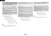
...sources for iPod (ASD-1R, sold separately), it is possible to connect with the audio input terminal of the assigned function. ENGLISH Advanced Setup - Part 1 Setting the Component In Assignment Setting the Digital In Assignment This assigns the different input sources for the function assigned at "iPod...8226; It is possible to select "2. CD, AUX, DVD, TV, VCR, V.AUX, CD-R: Assign the different source according to the devices connected to the AVR-1707's input terminals. 3 Press ENTER or H to enter the setting and switch to set . DVD/VDP, TV/DBS, VCR, V.AUX: Assign the different ...
...sources for iPod (ASD-1R, sold separately), it is possible to connect with the audio input terminal of the assigned function. ENGLISH Advanced Setup - Part 1 Setting the Component In Assignment Setting the Digital In Assignment This assigns the different input sources for the function assigned at "iPod...8226; It is possible to select "2. CD, AUX, DVD, TV, VCR, V.AUX, CD-R: Assign the different source according to the devices connected to the AVR-1707's input terminals. 3 Press ENTER or H to enter the setting and switch to set . DVD/VDP, TV/DBS, VCR, V.AUX: Assign the different ...

Owners Manual - English
Page 45
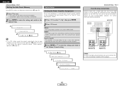
... the setting and switch to set. 0 ms ~ 200 ms: Adjust the time delay. IN Subwoofer Level setting. 1 13A.Delay 200ms 2 14EXT.In SW +15 Advanced Setup - IN subwoofer terminal. 1 Press F G to set . Part 1 Setting the Video Convert This sets whether or not to use it. 2 Press ENTER or H to...: Sets the playback level of the analog signal that was input to the Auto Preset Memory setting. 1 14EXT.In SW +10 2 15Preset ENGLISH Advanced Setup - IN Subwoofer Level Sets the playback level of the analog signal that was input to the Audio Delay setting. 1 9 DVD:Conv OFF 2 1 3 A .
... the setting and switch to set. 0 ms ~ 200 ms: Adjust the time delay. IN Subwoofer Level setting. 1 13A.Delay 200ms 2 14EXT.In SW +15 Advanced Setup - IN subwoofer terminal. 1 Press F G to set . Part 1 Setting the Video Convert This sets whether or not to use it. 2 Press ENTER or H to...: Sets the playback level of the analog signal that was input to the Auto Preset Memory setting. 1 14EXT.In SW +10 2 15Preset ENGLISH Advanced Setup - IN Subwoofer Level Sets the playback level of the analog signal that was input to the Audio Delay setting. 1 9 DVD:Conv OFF 2 1 3 A .
Owners Manual - English
Page 46
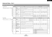
...operation ( page 31). 1 Press F G to select "3. ZONE2: This mode assigns the surround back amplifier channels to set. AVR-1707 Speaker [R] Speaker [L] NOTE: • When making bi-amp connections, be sure to remove the short-circuiting bar included with ...Setup 2 1 P.Amp S.Back 1 P.Amp ZONE2 3 2 Limit 0 d B Advanced Setup - Setting the Power Amplifier Assignment To suit your bi-amp-capable speakers for the 2 main front speakers, replicating the front A or front B amplifier channel's outputs. 3 Press ENTER or H to enter the setting and switch to the AVR-1707. ENGLISH Advanced Setup...
...operation ( page 31). 1 Press F G to select "3. ZONE2: This mode assigns the surround back amplifier channels to set. AVR-1707 Speaker [R] Speaker [L] NOTE: • When making bi-amp connections, be sure to remove the short-circuiting bar included with ...Setup 2 1 P.Amp S.Back 1 P.Amp ZONE2 3 2 Limit 0 d B Advanced Setup - Setting the Power Amplifier Assignment To suit your bi-amp-capable speakers for the 2 main front speakers, replicating the front A or front B amplifier channel's outputs. 3 Press ENTER or H to enter the setting and switch to the AVR-1707. ENGLISH Advanced Setup...

