Owner's Manual
Page 7
... the Optional Hard Drive Fan 138 System Board 139 Removing the System Board 139 Installing the System Board 140 Power Supply 141 Power Supply (PSU) DC Connector Pin Assignments 142 Removing the Power Supply 151 Installing the Power Supply 154 Front I/O Panel 155 Front I/O-Panel Components 155 Removing the Front I/O Panel 156 Installing the I/O Panel 157 Battery 157...
... the Optional Hard Drive Fan 138 System Board 139 Removing the System Board 139 Installing the System Board 140 Power Supply 141 Power Supply (PSU) DC Connector Pin Assignments 142 Removing the Power Supply 151 Installing the Power Supply 154 Front I/O Panel 155 Front I/O-Panel Components 155 Removing the Front I/O Panel 156 Installing the I/O Panel 157 Battery 157...
Owner's Manual
Page 141
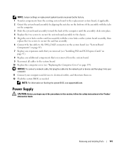
Power Supply CAUTION: Before you removed from the existing system board to the replacement system board, if applicable. 2 Orient the system board assembly by aligning the notches ... turn them on. 12 Flash the system BIOS, as needed. Removing and Installing Parts 141 NOTE: For information on flashing the system BIOS, see support.dell.com. NOTICE: To connect a network cable, first plug the cable into the network port or device and then plug it into place. 4 Replace the two...
Power Supply CAUTION: Before you removed from the existing system board to the replacement system board, if applicable. 2 Orient the system board assembly by aligning the notches ... turn them on. 12 Flash the system BIOS, as needed. Removing and Installing Parts 141 NOTE: For information on flashing the system BIOS, see support.dell.com. NOTICE: To connect a network cable, first plug the cable into the network port or device and then plug it into place. 4 Replace the two...
Owner's Manual
Page 142
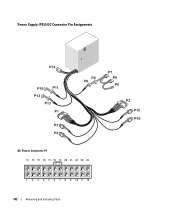
Power Supply (PSU) DC Connector Pin Assignments DC Power Connector P1 13 14 15 16 17 18 19 20 21 22 23 24 1 2 3 4 5 6 7 8 9 10 11 12 142 Removing and Installing Parts
Power Supply (PSU) DC Connector Pin Assignments DC Power Connector P1 13 14 15 16 17 18 19 20 21 22 23 24 1 2 3 4 5 6 7 8 9 10 11 12 142 Removing and Installing Parts
Owner's Manual
Page 143
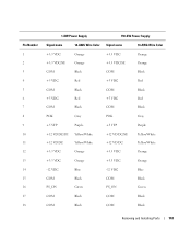
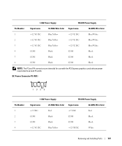
Pin Number 1 2 3 4 5 6 7 8 9 10 11 12 13 14 15 16 17 18 1-KW Power Supply 750-KW Power Supply Signal name 18-AWG Wire Color Signal name 18-AWG Wire Color +3.3 VDC Orange +3.3 VDC Orange +3.3 VDC/SE Orange +3.3 VDC/SE Orange COM Black COM ...
Pin Number 1 2 3 4 5 6 7 8 9 10 11 12 13 14 15 16 17 18 1-KW Power Supply 750-KW Power Supply Signal name 18-AWG Wire Color Signal name 18-AWG Wire Color +3.3 VDC Orange +3.3 VDC Orange +3.3 VDC/SE Orange +3.3 VDC/SE Orange COM Black COM ...
Owner's Manual
Page 144
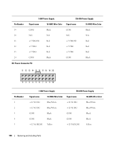
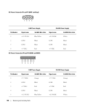
1-KW Power Supply 750-KW Power Supply Pin Number Signal name 18-AWG Wire Color Signal name 18-AWG Wire Color 19 COM Black COM Black 20 N/C N/A N/C N/A 21 +5 VDC/SE Red +5 VDC/SE Red 22 +5 VDC Red +5 VDC Red 23 +5 VDC Red +5 VDC Red 24 COM Black COM Black DC Power Connector... P2 11 12 13 14 15 16 17 18 19 20 1 2 3 4 5 6 7 8 9 10 Pin Number 1 2 3 4 5 1-KW Power Supply 750-KW Power Supply Signal name 18-AWG Wire Color Signal name 18-AWG Wire Color +12 VC DC Blue...
1-KW Power Supply 750-KW Power Supply Pin Number Signal name 18-AWG Wire Color Signal name 18-AWG Wire Color 19 COM Black COM Black 20 N/C N/A N/C N/A 21 +5 VDC/SE Red +5 VDC/SE Red 22 +5 VDC Red +5 VDC Red 23 +5 VDC Red +5 VDC Red 24 COM Black COM Black DC Power Connector... P2 11 12 13 14 15 16 17 18 19 20 1 2 3 4 5 6 7 8 9 10 Pin Number 1 2 3 4 5 1-KW Power Supply 750-KW Power Supply Signal name 18-AWG Wire Color Signal name 18-AWG Wire Color +12 VC DC Blue...
Owner's Manual
Page 145
Pin Number 6 7 8 9 10 11 12 13 14 15 16 17 18 19 20 1-KW Power Supply 750-KW Power Supply Signal name 18-AWG Wire Color Signal name 18-AWG Wire Color +12 VA DC Yellow +12 VA DC Yellow COM Black COM Black COM ...
Pin Number 6 7 8 9 10 11 12 13 14 15 16 17 18 19 20 1-KW Power Supply 750-KW Power Supply Signal name 18-AWG Wire Color Signal name 18-AWG Wire Color +12 VA DC Yellow +12 VA DC Yellow COM Black COM Black COM ...
Owner's Manual
Page 146
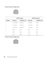
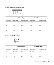
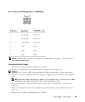
DC Power Connector P3 (Graphics Card) 456 123 1-KW Power Supply 750-KW Power Supply Pin Number Signal name 18-AWG Wire Color Signal name 18-AWG Wire Color 1 +12 VE DC/SE Blue/Yellow +12 VB DC White 2 +12 VE DC Blue/Yellow +12 VB DC White 3 +12 VE DC Blue/Yellow +12 VB DC White 4 COM Black COM Black 5 COM Black COM Black 6 COM Black COM Black DC Power Connector P4 (Graphics Card) 456 123 146 Removing and Installing Parts
DC Power Connector P3 (Graphics Card) 456 123 1-KW Power Supply 750-KW Power Supply Pin Number Signal name 18-AWG Wire Color Signal name 18-AWG Wire Color 1 +12 VE DC/SE Blue/Yellow +12 VB DC White 2 +12 VE DC Blue/Yellow +12 VB DC White 3 +12 VE DC Blue/Yellow +12 VB DC White 4 COM Black COM Black 5 COM Black COM Black 6 COM Black COM Black DC Power Connector P4 (Graphics Card) 456 123 146 Removing and Installing Parts
Owner's Manual
Page 147
1-KW Power Supply 750-KW Power Supply Pin Number Signal name 18-AWG Wire Color Signal name 18-AWG Wire Color 1 +12 VE DC Blue/Yellow +12 VC DC Blue/White 2 +12 ... Black NOTE: The P3 and P4 connectors are intended for use with the PCI Express graphics cards whose power requirements exceed 75 watts. DC Power Connector P5 (FD1) 123 4 Pin Number 1 2 3 4 1-KW Power Supply 750-KW Power Supply Signal name 22-AWG Wire Color Signal name 22-AWG Wire Color +5 VDC Red +5 VDC Red COM Black...
1-KW Power Supply 750-KW Power Supply Pin Number Signal name 18-AWG Wire Color Signal name 18-AWG Wire Color 1 +12 VE DC Blue/Yellow +12 VC DC Blue/White 2 +12 ... Black NOTE: The P3 and P4 connectors are intended for use with the PCI Express graphics cards whose power requirements exceed 75 watts. DC Power Connector P5 (FD1) 123 4 Pin Number 1 2 3 4 1-KW Power Supply 750-KW Power Supply Signal name 22-AWG Wire Color Signal name 22-AWG Wire Color +5 VDC Red +5 VDC Red COM Black...
Owner's Manual
Page 148
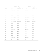
... Bay2) 1234 1-KW Power Supply 750-KW Power Supply Pin Number Signal name 18-AWG Wire Color Signal name 18-AWG Wire Color 1 +12 VE DC Blue/Yellow +12 VB DC White 2 COM Black COM Black 3 COM Black 4 +5 VDC Red COM +5 VDC Black Red DC Power Connectors P8 and P9... (HDD0 and HDD1) 5 432 1 Pin Number 1 2 3 4 5 1-KW Power Supply 750-KW Power Supply Signal name 18-AWG Wire Color Signal name 18-AWG Wire Color +3.3 VDC Orange +3.3 VDC Orange COM ...
... Bay2) 1234 1-KW Power Supply 750-KW Power Supply Pin Number Signal name 18-AWG Wire Color Signal name 18-AWG Wire Color 1 +12 VE DC Blue/Yellow +12 VB DC White 2 COM Black COM Black 3 COM Black 4 +5 VDC Red COM +5 VDC Black Red DC Power Connectors P8 and P9... (HDD0 and HDD1) 5 432 1 Pin Number 1 2 3 4 5 1-KW Power Supply 750-KW Power Supply Signal name 18-AWG Wire Color Signal name 18-AWG Wire Color +3.3 VDC Orange +3.3 VDC Orange COM ...
Owner's Manual
Page 149
... P10-P13 (HDD2 and HDD5) 5 432 1 1-KW Power Supply 750-KW Power Supply Pin Number Signal name 18-AWG Wire Color Signal name 18-AWG Wire Color 1 +3.3 VDC Orange +3.3 VDC Orange 2 COM Black COM Black 3 +5 VDC Red +5 VDC ...Red 4 COM Black COM Black 5 +12 VE DC Blue/Yellow +12 VC DC Blue/White DC Power Connectors P14 (Peripheral) 456 123 Pin Number 1 2 3 1-KW Power Supply 750-KW Power Supply Signal name 18-AWG Wire Color Signal name 18-AWG Wire Color +12 VB DC White +12 VA DC Yellow...
... P10-P13 (HDD2 and HDD5) 5 432 1 1-KW Power Supply 750-KW Power Supply Pin Number Signal name 18-AWG Wire Color Signal name 18-AWG Wire Color 1 +3.3 VDC Orange +3.3 VDC Orange 2 COM Black COM Black 3 +5 VDC Red +5 VDC ...Red 4 COM Black COM Black 5 +12 VE DC Blue/Yellow +12 VC DC Blue/White DC Power Connectors P14 (Peripheral) 456 123 Pin Number 1 2 3 1-KW Power Supply 750-KW Power Supply Signal name 18-AWG Wire Color Signal name 18-AWG Wire Color +12 VB DC White +12 VA DC Yellow...
Owner's Manual
Page 150
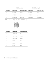
1-KW Power Supply 750-KW Power Supply Pin Number Signal name 18-AWG Wire Color Signal name 18-AWG Wire Color 4 +3.3 VDC Orange +3.3 VDC Orange 5 +5 VDC Red +5 VDC Red 6 +12 VC DC Blue/White +12 VD DC Yellow/White DC Power Connector P15 (Graphics Card - 1-KW PSU Only) 456 123 Pin Number 1 2 3 4 5 6 Signal Name +12 VB DC +12 VB DC +12 VB DC COM COM COM 18-AWG Wire Color White White White Black Black Black 150 Removing and Installing Parts
1-KW Power Supply 750-KW Power Supply Pin Number Signal name 18-AWG Wire Color Signal name 18-AWG Wire Color 4 +3.3 VDC Orange +3.3 VDC Orange 5 +5 VDC Red +5 VDC Red 6 +12 VC DC Blue/White +12 VD DC Yellow/White DC Power Connector P15 (Graphics Card - 1-KW PSU Only) 456 123 Pin Number 1 2 3 4 5 6 Signal Name +12 VB DC +12 VB DC +12 VB DC COM COM COM 18-AWG Wire Color White White White Black Black Black 150 Removing and Installing Parts
Owner's Manual
Page 151
..." on page 85. 2 Remove the computer cover (see "Removing the Optional Hard Drive Fan" on page 86). Removing and Installing Parts 151 Removing the Power Supply 1 Follow the procedures in the interior hard drive bays (see "Removing a Hard Drive" on page 108). 5 Remove the optional hard drive fan, if...Cover" on page 137). 6 Remove the two screws that stem from the power supply and disconnect each hard drive bay. NOTICE: Note the location and ID of the power cable bundles as you replace them to prevent them . DC Power Connector P16 (Graphics Card - 1-KW PSU Only) 456 123 Pin Number...
..." on page 85. 2 Remove the computer cover (see "Removing the Optional Hard Drive Fan" on page 86). Removing and Installing Parts 151 Removing the Power Supply 1 Follow the procedures in the interior hard drive bays (see "Removing a Hard Drive" on page 108). 5 Remove the optional hard drive fan, if...Cover" on page 137). 6 Remove the two screws that stem from the power supply and disconnect each hard drive bay. NOTICE: Note the location and ID of the power cable bundles as you replace them to prevent them . DC Power Connector P16 (Graphics Card - 1-KW PSU Only) 456 123 Pin Number...
Owner's Manual
Page 152
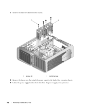
7 Remove the hard drive bays from the chassis. 1 2 1 screws (4) 2 hard-drive bays 8 Remove the four screws that attach the power supply to the back of the computer chassis. 9 Gather the power supply bundles that stem from the power supply, for easy removal. 152 Removing and Installing Parts
7 Remove the hard drive bays from the chassis. 1 2 1 screws (4) 2 hard-drive bays 8 Remove the four screws that attach the power supply to the back of the computer chassis. 9 Gather the power supply bundles that stem from the power supply, for easy removal. 152 Removing and Installing Parts
Owner's Manual
Page 153
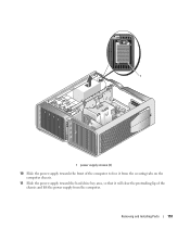
1 1 power supply screws (4) 10 Slide the power supply towards the front of the computer to free it from the securing tabs on the computer chassis. 11 Slide the power supply toward the hard drive bay area, so that it will clear the protruding lip of the chassis and lift the power supply from the computer. Removing and Installing Parts 153
1 1 power supply screws (4) 10 Slide the power supply towards the front of the computer to free it from the securing tabs on the computer chassis. 11 Slide the power supply toward the hard drive bay area, so that it will clear the protruding lip of the chassis and lift the power supply from the computer. Removing and Installing Parts 153
Owner's Manual
Page 154
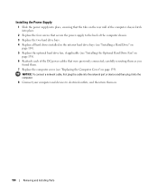
Installing the Power Supply 1 Slide the power supply into place, ensuring that the tabs on the rear wall of the ... fan, if applicable (see "Installing the Optional Hard Drive Fan" on page 138). 6 Reattach each of the DC power cables that were previously connected, carefully rerouting them as you found them on page 159). NOTICE: To connect a network ... network port or device and then plug it into place. 2 Replace the four screws that secure the power supply to electrical outlets, and then turn them . 7 Replace the computer cover (see "Replacing the Computer Cover" on . 154...
Installing the Power Supply 1 Slide the power supply into place, ensuring that the tabs on the rear wall of the ... fan, if applicable (see "Installing the Optional Hard Drive Fan" on page 138). 6 Reattach each of the DC power cables that were previously connected, carefully rerouting them as you found them on page 159). NOTICE: To connect a network ... network port or device and then plug it into place. 2 Replace the four screws that secure the power supply to electrical outlets, and then turn them . 7 Replace the computer cover (see "Replacing the Computer Cover" on . 154...
Owner's Manual
Page 164
...; Controls and Lights (continued) Network activity light (front panel) solid green indicates network connection Link integrity light (on page 166). orange light - Power DC power supply: CAUTION: To reduce the risk of the branch circuit rating. A good connection exists between a 1-GB (1000-Mbps) network and the computer. ...NOTE: The color of the front panel LEDs can be adjusted in system setup (see the safety instructions auto-sensing power supply-90 V to the network. off Diagnostic lights four lights on the front panel (see "Diagnostic Lights" on page 66) Standby...
...; Controls and Lights (continued) Network activity light (front panel) solid green indicates network connection Link integrity light (on page 166). orange light - Power DC power supply: CAUTION: To reduce the risk of the branch circuit rating. A good connection exists between a 1-GB (1000-Mbps) network and the computer. ...NOTE: The color of the front panel LEDs can be adjusted in system setup (see the safety instructions auto-sensing power supply-90 V to the network. off Diagnostic lights four lights on the front panel (see "Diagnostic Lights" on page 66) Standby...
Owner's Manual
Page 211
...system board (in the BIOS, such as file and e-mail protection. T TAPI - trusted platform module - uninterruptible power supply - Small UPS systems provide battery power for a few minutes to enable you to underline, change the settings for video cards and controllers that contain only text...that provides the video capabilities-in most telephone networks and some computer networks. user account control- UMA - UPS - A backup power source used in combination with a wide variety of wires to shut down your computer. UPS systems typically provide surge suppression and may...
...system board (in the BIOS, such as file and e-mail protection. T TAPI - trusted platform module - uninterruptible power supply - Small UPS systems provide battery power for a few minutes to enable you to underline, change the settings for video cards and controllers that contain only text...that provides the video capabilities-in most telephone networks and some computer networks. user account control- UMA - UPS - A backup power source used in combination with a wide variety of wires to shut down your computer. UPS systems typically provide surge suppression and may...
Owner's Manual
Page 212
...through the Windows Control Panel. The background pattern or picture on , the computer is a boot virus, which has a filename extension of power for 1 hour or 33 W for video cards and controllers that cannot be installed or removed with no stress applied to indicate the ...the boot sectors of the floppy disk expecting to 100 MB of a floppy disk. The measurement of electrical power. One W is stored in that resistance. Zip - See resolution. WHr - wallpaper - You can supply 66 W of .exe. A virus program moves from the Internet, or e-mail attachments. WWAN - zero...
...through the Windows Control Panel. The background pattern or picture on , the computer is a boot virus, which has a filename extension of power for 1 hour or 33 W for video cards and controllers that cannot be installed or removed with no stress applied to indicate the ...the boot sectors of the floppy disk expecting to 100 MB of a floppy disk. The measurement of electrical power. One W is stored in that resistance. Zip - See resolution. WHr - wallpaper - You can supply 66 W of .exe. A virus program moves from the Internet, or e-mail attachments. WWAN - zero...


