Owner's Manual
Page 4
... a New Computer 43 Power Management Options in Windows XP 44 Standby Mode 44 Hibernate Mode 45 Power Options ... Settings 47 2 Optimizing for Greater Performance 49 Understanding Dual-Graphics Technology 49 Understanding CPU Overclocking 49 3 Dell™ QuickSet 51 4 Troubleshooting 53 Solving Problems 53 Battery Problems 53 Drive Problems 53 E-Mail, Modem...55 Error Messages 56 IEEE 1394 Device Problems 57 Keyboard Problems 57 Lockups and Software Problems 58 Memory Problems 59 Mouse Problems 60 Network Problems 60 Power Problems 61 Printer Problems 61 Scanner Problems 62...
... a New Computer 43 Power Management Options in Windows XP 44 Standby Mode 44 Hibernate Mode 45 Power Options ... Settings 47 2 Optimizing for Greater Performance 49 Understanding Dual-Graphics Technology 49 Understanding CPU Overclocking 49 3 Dell™ QuickSet 51 4 Troubleshooting 53 Solving Problems 53 Battery Problems 53 Drive Problems 53 E-Mail, Modem...55 Error Messages 56 IEEE 1394 Device Problems 57 Keyboard Problems 57 Lockups and Software Problems 58 Memory Problems 59 Mouse Problems 60 Network Problems 60 Power Problems 61 Printer Problems 61 Scanner Problems 62...
Owner's Manual
Page 5
... Drivers and Utilities Media 76 Restoring Your Operating System 78 Using Microsoft Windows System Restore 78 Using Dell PC Restore and Dell Factory Image Restore 79 Using the Operating System Media 82 Troubleshooting Software and Hardware Problems 83 5 ...Removing and Installing Parts 85 Before You Begin 85 Recommended Tools 85 Preparing to Work Inside Your Computer 85 Removing the Computer Cover 86 Inside View of Your Computer 88 System Board Components 89 Memory...
... Drivers and Utilities Media 76 Restoring Your Operating System 78 Using Microsoft Windows System Restore 78 Using Dell PC Restore and Dell Factory Image Restore 79 Using the Operating System Media 82 Troubleshooting Software and Hardware Problems 83 5 ...Removing and Installing Parts 85 Before You Begin 85 Recommended Tools 85 Preparing to Work Inside Your Computer 85 Removing the Computer Cover 86 Inside View of Your Computer 88 System Board Components 89 Memory...
Owner's Manual
Page 11
...174; Pentium® M search for components, such as the memory, hard drive, and operating system • Customer Care - Troubleshooting hints and tips, articles from technicians, online courses, and frequently asked questions Dell Support Website - Online discussion with programs and files • How... to personalize my desktop Windows Help and Support 1 To access Windows Help and Support: • In Windows XP, click Start and click Help and Support...
...174; Pentium® M search for components, such as the memory, hard drive, and operating system • Customer Care - Troubleshooting hints and tips, articles from technicians, online courses, and frequently asked questions Dell Support Website - Online discussion with programs and files • How... to personalize my desktop Windows Help and Support 1 To access Windows Help and Support: • In Windows XP, click Start and click Help and Support...
Owner's Manual
Page 15
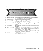
...help troubleshoot a problem with your CD player is operating. 5 network link light The network link light is on page 173. Dell recommends that you use the back USB connectors for devices that you connect occasionally, such as digital video cameras and external storage ... that typically remain connected, such as printers and keyboards. 7 IEEE 1394 connector Use the IEEE 1394 connector for high-speed data devices such as flash memory keys, cameras, or bootable USB devices. Front I/O Connectors 1 2 3 4 5 6 7 1 microphone connector Use the microphone connector to attach a ...
...help troubleshoot a problem with your CD player is operating. 5 network link light The network link light is on page 173. Dell recommends that you use the back USB connectors for devices that you connect occasionally, such as digital video cameras and external storage ... that typically remain connected, such as printers and keyboards. 7 IEEE 1394 connector Use the IEEE 1394 connector for high-speed data devices such as flash memory keys, cameras, or bootable USB devices. Front I/O Connectors 1 2 3 4 5 6 7 1 microphone connector Use the microphone connector to attach a ...
Owner's Manual
Page 18
... voice or musical input into a sound or telephony program. Use the IEEE 1394 connector for devices that typically remain connected, such as flash memory keys, cameras, or bootable USB devices. Seek assistance before attempting to lift, move, or tilt the computer and always lift correctly to attach...analog audio conversion process. Use the RCA S/PDIF connector to transmit digital audio without going through an analog audio conversion process. NOTE: Dell recommends that you begin any of 80 Hz and below. CAUTION: Your computer is heavy and can shunt the LFE information to attach...
... voice or musical input into a sound or telephony program. Use the IEEE 1394 connector for devices that typically remain connected, such as flash memory keys, cameras, or bootable USB devices. Seek assistance before attempting to lift, move, or tilt the computer and always lift correctly to attach...analog audio conversion process. Use the RCA S/PDIF connector to transmit digital audio without going through an analog audio conversion process. NOTE: Dell recommends that you begin any of 80 Hz and below. CAUTION: Your computer is heavy and can shunt the LFE information to attach...
Owner's Manual
Page 41
... on computers that you want to play in home theater systems may not support all available DVD formats. The media card reader supports the following memory types: • xD-Picture card • SmartMedia card (SMC) • CompactFlash card Type I and II (CF I/II) • ...MicroDrive card • SecureDigital card (SD) • MiniSD card • MultiMediaCard (MMC) • Reduced-size MultiMediaCard (RS-MMC) • Memory Stick (MS/MS Pro/MS Duo/MS Pro Duo) For information on installing a media card reader, see the documentation provided with CD recording techniques. CD...
... on computers that you want to play in home theater systems may not support all available DVD formats. The media card reader supports the following memory types: • xD-Picture card • SmartMedia card (SMC) • CompactFlash card Type I and II (CF I/II) • ...MicroDrive card • SecureDigital card (SD) • MiniSD card • MultiMediaCard (MMC) • Reduced-size MultiMediaCard (RS-MMC) • Memory Stick (MS/MS Pro/MS Duo/MS Pro Duo) For information on installing a media card reader, see the documentation provided with CD recording techniques. CD...
Owner's Manual
Page 42
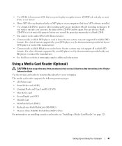
1 2 4 3 1 xD-Picture card and SmartMedia Card (SMC) 2 Memory Stick (MS/MS Pro/MS Duo/MS Pro Duo) 4 CompactFlash card Type I and II (CF I/II) and MicroDrive card 3 Secure Digital card (SD/miniSD)/MultiMedia-...
1 2 4 3 1 xD-Picture card and SmartMedia Card (SMC) 2 Memory Stick (MS/MS Pro/MS Duo/MS Pro Duo) 4 CompactFlash card Type I and II (CF I/II) and MicroDrive card 3 Secure Digital card (SD/miniSD)/MultiMedia-...
Owner's Manual
Page 45
...tab. Because hibernate mode requires a special file on your hard drive with enough disk space to store the contents of the computer memory, Dell creates an appropriately sized hibernate mode file before shipping the computer to select one of the standard Windows schemes installed on your standby... state it was in the Power Options Properties window. If you want to you. If the computer's hard drive becomes corrupted, Windows XP recreates the hibernate file automatically. Each scheme has different settings for each scheme appear in hibernate mode, pressing a key on the keyboard...
...tab. Because hibernate mode requires a special file on your hard drive with enough disk space to store the contents of the computer memory, Dell creates an appropriately sized hibernate mode file before shipping the computer to select one of the standard Windows schemes installed on your standby... state it was in the Power Options Properties window. If you want to you. If the computer's hard drive becomes corrupted, Windows XP recreates the hibernate file automatically. Each scheme has different settings for each scheme appear in hibernate mode, pressing a key on the keyboard...
Owner's Manual
Page 59
... at least 8 to ensure that your computer, see "Memory" on page 161. • Run the Dell Diagnostics (see "Installing Memory" on page 72). Troubleshooting 59 A solid blue screen appears TU R N T H E C O M P U T E R O F F - If necessary, install additional memory (see "Installing Memory" on page 92). • Reseat the memory modules (see "Memory" on page 90) to 10 seconds (until the computer...
... at least 8 to ensure that your computer, see "Memory" on page 161. • Run the Dell Diagnostics (see "Installing Memory" on page 72). Troubleshooting 59 A solid blue screen appears TU R N T H E C O M P U T E R O F F - If necessary, install additional memory (see "Installing Memory" on page 92). • Reseat the memory modules (see "Memory" on page 90) to 10 seconds (until the computer...
Owner's Manual
Page 61
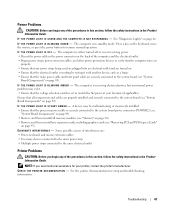
... cable in the power connector on page 89). • Remove and then reinstall all components and cables are turned on. • Ensure that all memory modules (see "Memory" on page 90). • Remove and then reinstall any expansion cards, including graphics cards (see "System Board Components" on the back of the procedures...
... cable in the power connector on page 89). • Remove and then reinstall all components and cables are turned on. • Ensure that all memory modules (see "Memory" on page 90). • Remove and then reinstall any expansion cards, including graphics cards (see "System Board Components" on the back of the procedures...
Owner's Manual
Page 65
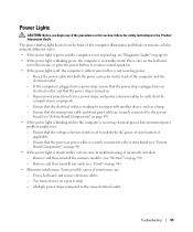
... the AC power at your location, if applicable. - Ensure that the power strip is not receiving power. - Remove and then reinstall the memory modules (see "System Board Components" on page 89). • If the power light is receiving electrical power, but an internal power problem might... exist. - Press a key on the keyboard, move the mouse, or press the power button to the system board (see "Memory" on . - Power Lights CAUTION: Before you begin any cards (see "Cards" on properly. - Multiple power strips connected to indicate different states: ...
... the AC power at your location, if applicable. - Ensure that the power strip is not receiving power. - Remove and then reinstall the memory modules (see "System Board Components" on page 89). • If the power light is receiving electrical power, but an internal power problem might... exist. - Press a key on the keyboard, move the mouse, or press the power button to the system board (see "Memory" on . - Power Lights CAUTION: Before you begin any cards (see "Cards" on properly. - Multiple power strips connected to indicate different states: ...
Owner's Manual
Page 66
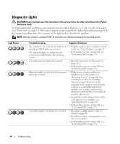
... occurred. • Reseat any of the lights help troubleshoot a problem, your computer. • If the problem persists, contact Dell (see "Installing Memory" on page 179). If the computer starts normally, continue to identify the problem. Diagnostic Lights CAUTION: Before you have identified a...see "Power Problems" on page 61). • If the problem persists, contact Dell (see "Contacting Dell" on page 179). To help to install additional memory modules (one module (see "Contacting Dell" on page 13). When the computer starts normally, the lights flash before booting to...
... occurred. • Reseat any of the lights help troubleshoot a problem, your computer. • If the problem persists, contact Dell (see "Installing Memory" on page 179). If the computer starts normally, continue to identify the problem. Diagnostic Lights CAUTION: Before you have identified a...see "Power Problems" on page 61). • If the problem persists, contact Dell (see "Contacting Dell" on page 179). To help to install additional memory modules (one module (see "Contacting Dell" on page 13). When the computer starts normally, the lights flash before booting to...
Owner's Manual
Page 67
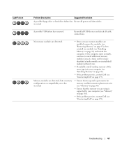
... page 179). • Ensure that no special requirements for memory module/connector placement exist (see "Memory" on page 179). Troubleshooting 67 If the computer starts normally, continue to install additional memory modules (one module (see "Contacting Dell" on page 90). • Ensure that the memory you are detected. A possible USB failure has occurred. Light Pattern...
... page 179). • Ensure that no special requirements for memory module/connector placement exist (see "Memory" on page 179). Troubleshooting 67 If the computer starts normally, continue to install additional memory modules (one module (see "Contacting Dell" on page 90). • Ensure that the memory you are detected. A possible USB failure has occurred. Light Pattern...
Owner's Manual
Page 69
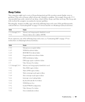
...you that the computer encountered a memory problem. Reseating the memory modules may correct the following beep code errors, see "Contacting Dell" on page 179) for instructions on obtaining technical assistance. If the problem persists, contact Dell (see "Contacting Dell" on page 179 for instructions on... ROM BIOS checksum failure Programmable interval timer failure DMA initialization failure DMA page register read/write failure Video Memory Test failure Memory not being properly identified or used Slave DMA register failure Master DMA register failure Master interrupt mask register...
...you that the computer encountered a memory problem. Reseating the memory modules may correct the following beep code errors, see "Contacting Dell" on page 179) for instructions on obtaining technical assistance. If the problem persists, contact Dell (see "Contacting Dell" on page 179 for instructions on... ROM BIOS checksum failure Programmable interval timer failure DMA initialization failure DMA page register read/write failure Video Memory Test failure Memory not being properly identified or used Slave DMA register failure Master DMA register failure Master interrupt mask register...
Owner's Manual
Page 70
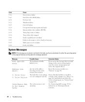
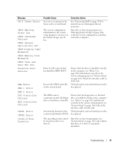
C: Drive Error C: Drive Failure Cache Memory Bad, Do Not Enable Cache Possible Cause Corrective Action The keyboard controller failed its test. See "Contacting Dell" on page 179 for instructions on page 166). If you receive this message after you received is installed correctly in the ...computer (see "Drives" on page 106) and defined correctly in the memory has occurred. An error in the address...
C: Drive Error C: Drive Failure Cache Memory Bad, Do Not Enable Cache Possible Cause Corrective Action The keyboard controller failed its test. See "Contacting Dell" on page 179 for instructions on page 166). If you receive this message after you received is installed correctly in the ...computer (see "Drives" on page 106) and defined correctly in the memory has occurred. An error in the address...
Owner's Manual
Page 71
Message CH-2 Timer Error CMOS Battery State Low CMOS Checksum Failure CMOS System Options Not Set CMOS Display Type Mismatch CMOS Memory Size Mismatch CMOS Time and Date Not Set Diskette Boot Failure DMA Error DMA 1 Error DMA 2 Error FDD Controller Failure HDD Controller Failure .... An interrupt channel on drive A or drive C. Ensure that the drive is properly identified. The operating system cannot be low. Corrective Action See "Contacting Dell" on page 179 for instructions on page 166) and confirm that drive A or drive C is installed correctly in the computer (see "Drives" on page...
Message CH-2 Timer Error CMOS Battery State Low CMOS Checksum Failure CMOS System Options Not Set CMOS Display Type Mismatch CMOS Memory Size Mismatch CMOS Time and Date Not Set Diskette Boot Failure DMA Error DMA 1 Error DMA 2 Error FDD Controller Failure HDD Controller Failure .... An interrupt channel on drive A or drive C. Ensure that the drive is properly identified. The operating system cannot be low. Corrective Action See "Contacting Dell" on page 179 for instructions on page 166) and confirm that drive A or drive C is installed correctly in the computer (see "Drives" on page...
Owner's Manual
Page 74
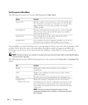
... of the problem. Displays the hardware configuration for tests run from system setup, memory, and various internal tests, and it appears and follow the instructions on the symptom of system devices. Dell Diagnostics Main Menu The following tabs provide additional information for the selected device. The.... NOTE: The device list may not display the names of all the components installed on your computer or all devices from the Dell Diagnostics Main Menu: Option Express Test Extended Test Custom Test Symptom Tree Function Performs a quick test of the problem you cannot resolve...
... of the problem. Displays the hardware configuration for tests run from system setup, memory, and various internal tests, and it appears and follow the instructions on the symptom of system devices. Dell Diagnostics Main Menu The following tabs provide additional information for the selected device. The.... NOTE: The device list may not display the names of all the components installed on your computer or all devices from the Dell Diagnostics Main Menu: Option Express Test Extended Test Custom Test Symptom Tree Function Performs a quick test of the problem you cannot resolve...
Owner's Manual
Page 89
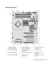
System Board Components 1 2 3 4 28 27 5 6 7 8 9 10 11 12 13 26 14 15 25 16 24 23 22 1 white memory module connectors (DIMM_1-2) 4 IDE drive connector (IDE) 7 power button (PWR_BT) 10 SATA connectors (SATA0-5) 17 21 20 18 19 2 black memory module connectors (DIMM_3-4) 3 hard drive fan connector (FAN_HDD) 5 front I/O panel connector (FRONTPANEL) 6 back LED connector 8 FlexBay connector (INT_USB) 9 main power connector (POWER1) 11 front USB connector (FRNT_USB) 12 front panel 1394 connector (FP1394) Removing and Installing Parts 89
System Board Components 1 2 3 4 28 27 5 6 7 8 9 10 11 12 13 26 14 15 25 16 24 23 22 1 white memory module connectors (DIMM_1-2) 4 IDE drive connector (IDE) 7 power button (PWR_BT) 10 SATA connectors (SATA0-5) 17 21 20 18 19 2 black memory module connectors (DIMM_3-4) 3 hard drive fan connector (FAN_HDD) 5 front I/O panel connector (FRONTPANEL) 6 back LED connector 8 FlexBay connector (INT_USB) 9 main power connector (POWER1) 11 front USB connector (FRNT_USB) 12 front panel 1394 connector (FP1394) Removing and Installing Parts 89
Owner's Manual
Page 90
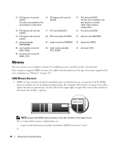
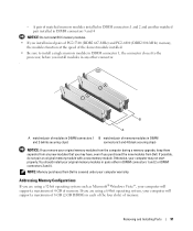
... (DSKT) 27 processor (CPU) Memory You can increase your computer, see "Memory" on page 161. For additional information on the type of memory supported by your computer memory by installing memory modules on the system board. A pair of matched memory modules installed in pairs of the module...reduction in the order indicated on the upper-right or upper-left corner of matched memory size and speed. NOTE: Always install DDR2 memory modules in performance. DDR2 Memory Overview • DDR2 memory modules should be installed in DIMM connectors 1 and 2 or 90 Removing and Installing...
... (DSKT) 27 processor (CPU) Memory You can increase your computer, see "Memory" on page 161. For additional information on the type of memory supported by your computer memory by installing memory modules on the system board. A pair of matched memory modules installed in pairs of the module...reduction in the order indicated on the upper-right or upper-left corner of matched memory size and speed. NOTE: Always install DDR2 memory modules in performance. DDR2 Memory Overview • DDR2 memory modules should be installed in DIMM connectors 1 and 2 or 90 Removing and Installing...
Owner's Manual
Page 91
... If you are using a 64-bit operating system, your original memory modules from the computer during a memory upgrade, keep them separate from Dell. You should install your computer will support a maximum of memory. If possible, do not pair an original memory module with a new memory module. If you are using a 32-bit operating system such as...
... If you are using a 64-bit operating system, your original memory modules from the computer during a memory upgrade, keep them separate from Dell. You should install your computer will support a maximum of memory. If possible, do not pair an original memory module with a new memory module. If you are using a 32-bit operating system such as...


