Owner's Manual
Page 10
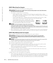
... not operate your location. Set the switch to AC power. Always follow installation and service instructions closely. Doing so reduces the potential for personal injury or shock. Also, disconnect any static electricity that most closely matches the voltage used in your computer with any cover(s) (including computer covers, bezels, filler brackets, front-panel inserts, and so on) removed. • Your computer is connected to...
... not operate your location. Set the switch to AC power. Always follow installation and service instructions closely. Doing so reduces the potential for personal injury or shock. Also, disconnect any static electricity that most closely matches the voltage used in your computer with any cover(s) (including computer covers, bezels, filler brackets, front-panel inserts, and so on) removed. • Your computer is connected to...
Owner's Manual
Page 17
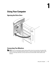
If you are connecting two flat-panel monitors, at least one monitor (VGA or DVI) in addition to the television. Using Your Computer 17 If you are connecting a television, you must have the optional VGA adapter. Using Your Computer Opening the Drive Door Connecting Two Monitors NOTE: If you are connecting two monitors that have VGA connectors, you may connect only one of them must have a VGA connector.
If you are connecting two flat-panel monitors, at least one monitor (VGA or DVI) in addition to the television. Using Your Computer 17 If you are connecting a television, you must have the optional VGA adapter. Using Your Computer Opening the Drive Door Connecting Two Monitors NOTE: If you are connecting two monitors that have VGA connectors, you may connect only one of them must have a VGA connector.
Owner's Manual
Page 20
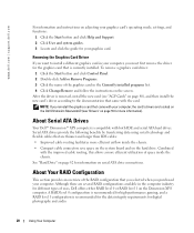
... audio. 20 Using Your Computer About Your RAID Configuration This section provides an overview of the graphics card in the computer industry for information on serial ATA drive connections. A RAID level 0 configuration is recommended for high-performance gaming, and a RAID level 1 configuration is compatible with the improved cable routing, this allows a more efficient airflow inside the chassis. To remove a graphics card driver: 1 Click the Start button and click Control Panel. 2 Double-click Add or Remove...
... audio. 20 Using Your Computer About Your RAID Configuration This section provides an overview of the graphics card in the computer industry for information on serial ATA drive connections. A RAID level 0 configuration is recommended for high-performance gaming, and a RAID level 1 configuration is compatible with the improved cable routing, this allows a more efficient airflow inside the chassis. To remove a graphics card driver: 1 Click the Start button and click Control Panel. 2 Double-click Add or Remove...
Owner's Manual
Page 45
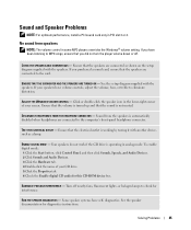
... screen. Click or double-click the speaker icon in some MP3 players overrides the Windows® volume setting. See the speaker documentation for interference. See the setup diagram supplied with the speakers. Ensure that the volume is turned up and that the speakers are connected to eliminate distortion. To enable digital mode: 1 Click the Start button, click Control Panel, and then click Sounds, Speech, and Audio Devices. 2 Click Sounds and Audio Devices. 3 Click the Hardware...
... screen. Click or double-click the speaker icon in some MP3 players overrides the Windows® volume setting. See the speaker documentation for interference. See the setup diagram supplied with the speakers. Ensure that the volume is turned up and that the speakers are connected to eliminate distortion. To enable digital mode: 1 Click the Start button, click Control Panel, and then click Sounds, Speech, and Audio Devices. 2 Click Sounds and Audio Devices. 3 Click the Hardware...
Owner's Manual
Page 46
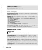
.... DISABLE DIGITAL MODE - ADJUST THE WINDOWS VOLUME CONTROL - CHECK THE MONITOR CABLE CONNECTION - www.dell.com | support.dell.com REINSTALL THE AUDIO (SOUND) DRIVER - Ensure that the video cable is blinking, press a key on the keyboard or move the mouse. CHECK FOR INTERRUPT REQUEST CONFLICTS - If the power light is connected as a lamp. 46 Solving Problems See page 55. To disable digital mode: 1 Click the Start button, click Control Panel, and then click Sounds, Speech, and Audio Devices. 2 Click Sounds and Audio Devices. 3 Click the Hardware...
.... DISABLE DIGITAL MODE - ADJUST THE WINDOWS VOLUME CONTROL - CHECK THE MONITOR CABLE CONNECTION - www.dell.com | support.dell.com REINSTALL THE AUDIO (SOUND) DRIVER - Ensure that the video cable is blinking, press a key on the keyboard or move the mouse. CHECK FOR INTERRUPT REQUEST CONFLICTS - If the power light is connected as a lamp. 46 Solving Problems See page 55. To disable digital mode: 1 Click the Start button, click Control Panel, and then click Sounds, Speech, and Audio Devices. 2 Click Sounds and Audio Devices. 3 Click the Hardware...

Owner's Manual
Page 49
... lights display solid green. Advanced Troubleshooting 49 ABCD A possible processor failure has occurred. ABCD Memory modules are locked. 3 Restart the computer. 4 If the problem persists, contact Dell (see page 112). Advanced Troubleshooting Diagnostic Lights To help you occurred. The lights can be yellow or green. Light Pattern ABCD Problem Description Suggested Resolution The computer is in this section, follow the safety instructions on the back panel...
... lights display solid green. Advanced Troubleshooting 49 ABCD A possible processor failure has occurred. ABCD Memory modules are locked. 3 Restart the computer. 4 If the problem persists, contact Dell (see page 112). Advanced Troubleshooting Diagnostic Lights To help you occurred. The lights can be yellow or green. Light Pattern ABCD Problem Description Suggested Resolution The computer is in this section, follow the safety instructions on the back panel...
Owner's Manual
Page 56
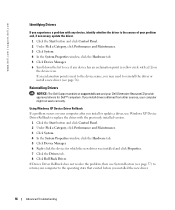
... Device Manager. 6 Scroll down the list to replace the driver with a [!]) on your computer after you install or update a driver, use System Restore (see page 57) to return your computer to reinstall the driver or install a new driver (see if any device, identify whether the driver is next to the device name, you may need to the operating state that existed before you installed the new driver. 56 Advanced Troubleshooting Using Windows XP Device Driver Rollback If a problem occurs...
... Device Manager. 6 Scroll down the list to replace the driver with a [!]) on your computer after you install or update a driver, use System Restore (see page 57) to return your computer to reinstall the driver or install a new driver (see if any device, identify whether the driver is next to the device name, you may need to the operating state that existed before you installed the new driver. 56 Advanced Troubleshooting Using Windows XP Device Driver Rollback If a problem occurs...
Owner's Manual
Page 66
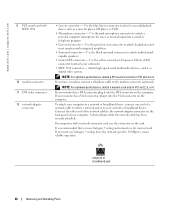
... you use Category 3 wiring, force the network speed to 10 Mbps to attach your monitor has a DVI connector, plug it into the VGA connector on the computer. Use the green line-out connector to attach multichannelcapable speakers. • Center/LFE connector - Use the pink microphone connector to the modem connector (optional). NOTE: For optimum performance, install a PCI sound card only in PCI slot 2, 3, or 4. If your network. A click indicates that you have a modem, connect a telephone cable to...
... you use Category 3 wiring, force the network speed to 10 Mbps to attach your monitor has a DVI connector, plug it into the VGA connector on the computer. Use the green line-out connector to attach multichannelcapable speakers. • Center/LFE connector - Use the pink microphone connector to the modem connector (optional). NOTE: For optimum performance, install a PCI sound card only in PCI slot 2, 3, or 4. If your network. A click indicates that you have a modem, connect a telephone cable to...
Owner's Manual
Page 81
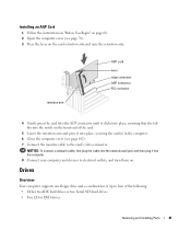
...). 7 Connect the monitor cable to four of the following: • Either two IDE hard drives or two Serial ATA hard drives. • Two CD or DVD drives. retention arm AGP card lever edge connector AGP connector PCI connector 4 Gently press the card into the AGP connector until it into the notch on . Removing and Installing Parts 81 Drives Overview Your computer supports one floppy drive and a combination of up to the card's video connector. Installing an AGP Card...
...). 7 Connect the monitor cable to four of the following: • Either two IDE hard drives or two Serial ATA hard drives. • Two CD or DVD drives. retention arm AGP card lever edge connector AGP connector PCI connector 4 Gently press the card into the AGP connector until it into the notch on . Removing and Installing Parts 81 Drives Overview Your computer supports one floppy drive and a combination of up to the card's video connector. Installing an AGP Card...
Owner's Manual
Page 122
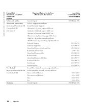
www.dell.com | support.dell.com Country (City) International Access Code Country Code City Code Netherlands Antilles Netherlands (Amsterdam) International Access Code: 00 Country Code: 31 City Code: 20 New Zealand International Access Code: 00 Country Code: 64 Nicaragua Department Name or Service Area, Website and E-Mail Address General Support Website: support.euro.dell.com E-mail (Technical Support): (Enterprise): nl_server_support@dell.com (Latitude): nl_latitude_support@dell.com (Inspiron): nl_inspiron_support@dell.com (Dimension): nl_dimension_support@dell.com (OptiPlex): ...
www.dell.com | support.dell.com Country (City) International Access Code Country Code City Code Netherlands Antilles Netherlands (Amsterdam) International Access Code: 00 Country Code: 31 City Code: 20 New Zealand International Access Code: 00 Country Code: 64 Nicaragua Department Name or Service Area, Website and E-Mail Address General Support Website: support.euro.dell.com E-mail (Technical Support): (Enterprise): nl_server_support@dell.com (Latitude): nl_latitude_support@dell.com (Inspiron): nl_inspiron_support@dell.com (Dimension): nl_dimension_support@dell.com (OptiPlex): ...
Owner's Manual
Page 132
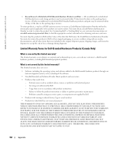
... instructions - See "Contacting Dell" or "Getting Help" in order to the Dell-branded hardware products through our factory-integration system, or the reloading of the date that result from the date on the packing slip or invoice. You must also return the products to perform preventive maintenance - Servicing not authorized by this limited warranty? Problems caused by using accessories, parts...
... instructions - See "Contacting Dell" or "Getting Help" in order to the Dell-branded hardware products through our factory-integration system, or the reloading of the date that result from the date on the packing slip or invoice. You must also return the products to perform preventive maintenance - Servicing not authorized by this limited warranty? Problems caused by using accessories, parts...
Owner's Manual
Page 139
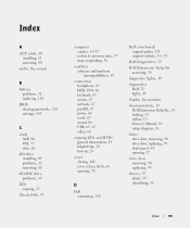
...online, 13 Owner's Manual, 14 setup diagram, 14 doors drive door, removing, 98 drive door, replacing, 99 front panel, 64 opening , 70 D Dell contacting, 112 Dell (continued) support policy, 111 support website, 13, 38 Dell Diagnostics, 52 Dell Dimension Help file accessing, 30 diagnostic lights, 49 diagnostics Dell, 52 lights, 49 display. Index A AGP cards, 80 installing, 81 removing, 80 audio. See sound B battery problems, 31 replacing, 101 BIOS clearing passwords, 110 settings, 109 C cards AGP, 80 PCI, 77 slots, 66 CD drive installing, 89 problems, 32 removing, 88 CD-RW drive problems, 33...
...online, 13 Owner's Manual, 14 setup diagram, 14 doors drive door, removing, 98 drive door, replacing, 99 front panel, 64 opening , 70 D Dell contacting, 112 Dell (continued) support policy, 111 support website, 13, 38 Dell Diagnostics, 52 Dell Dimension Help file accessing, 30 diagnostic lights, 49 diagnostics Dell, 52 lights, 49 display. Index A AGP cards, 80 installing, 81 removing, 80 audio. See sound B battery problems, 31 replacing, 101 BIOS clearing passwords, 110 settings, 109 C cards AGP, 80 PCI, 77 slots, 66 CD drive installing, 89 problems, 32 removing, 88 CD-RW drive problems, 33...
Owner's Manual
Page 141
... problems, 41 Network Setup Wizard, 25 O Operating System CD, 15 operating system reinstalling Windows XP, 60 overclocking, 28 P padlock ring, 66 passwords clearing, 110 PCI cards, 77 installing, 77 removing, 79 performance chip set, 27 Hyper-Threading, 27 Intel® Performance Acceleration Technology, 27 memory and front side bus, 27 overclocking, 28 Performance Acceleration Technology, 27 power button, 64 connector, 66 problems, 42 turning off your computer, 25 power light conditions, 42 power supply fans...
... problems, 41 Network Setup Wizard, 25 O Operating System CD, 15 operating system reinstalling Windows XP, 60 overclocking, 28 P padlock ring, 66 passwords clearing, 110 PCI cards, 77 installing, 77 removing, 79 performance chip set, 27 Hyper-Threading, 27 Intel® Performance Acceleration Technology, 27 memory and front side bus, 27 overclocking, 28 Performance Acceleration Technology, 27 power button, 64 connector, 66 problems, 42 turning off your computer, 25 power light conditions, 42 power supply fans...
Owner's Manual
Page 142
... board components, 73 System Restore, 57 system setup program, 109 clearing passwords, 110 T technical specifications, 105 technical support policy, 111 television connecting to your computer, 17 transferring information to a new computer, 22 troubleshooting conflicts, 59 Dell Diagnostics, 52 diagnostic lights, 49 Hardware Troubleshooter, 59 Help and Support Center, 14 restore to previous state, 57 Solving Problems, 29 turning off your computer, 25 V video connector, 66 problems, 46 volume adjusting, 45 W warranty, 128 Windows XP Device Driver Rollback, 56 Files and Settings...
... board components, 73 System Restore, 57 system setup program, 109 clearing passwords, 110 T technical specifications, 105 technical support policy, 111 television connecting to your computer, 17 transferring information to a new computer, 22 troubleshooting conflicts, 59 Dell Diagnostics, 52 diagnostic lights, 49 Hardware Troubleshooter, 59 Help and Support Center, 14 restore to previous state, 57 Solving Problems, 29 turning off your computer, 25 V video connector, 66 problems, 46 volume adjusting, 45 W warranty, 128 Windows XP Device Driver Rollback, 56 Files and Settings...

Service Manual
Page 10
... connector closest to the processor before you want to add another matched pair installed in the other connectors. For information on the type of matched memory size. NOTE: Always install DDR memory modules in pairs of memory supported by installing memory modules on the system board. Back to Contents Page Removing and Installing Parts Dell™ Dimension™ XPS Service Manual Memory AGP Cards Processor Airflow Shroud System Board Front Panel Battery PCI Cards Drives Processor Power Supply Drive Door Memory You can increase your computer memory...
... connector closest to the processor before you want to add another matched pair installed in the other connectors. For information on the type of matched memory size. NOTE: Always install DDR memory modules in pairs of memory supported by installing memory modules on the system board. Back to Contents Page Removing and Installing Parts Dell™ Dimension™ XPS Service Manual Memory AGP Cards Processor Airflow Shroud System Board Front Panel Battery PCI Cards Drives Processor Power Supply Drive Door Memory You can increase your computer memory...

Service Manual
Page 24
... the replacement system board. 3. b. Open the computer cover. 3. Before you remove the existing system board assembly, visually compare the replacement system board to the existing system board to make sure that the package and assembly have the correct part. 6. Remove the memory modules and install them on the existing system board. 4. Remove the heat-sink assembly and processor from the existing system board to the replacement system board: a. Orient the replacement board...
... the replacement system board. 3. b. Open the computer cover. 3. Before you remove the existing system board assembly, visually compare the replacement system board to the existing system board to make sure that the package and assembly have the correct part. 6. Remove the memory modules and install them on the existing system board. 4. Remove the heat-sink assembly and processor from the existing system board to the replacement system board: a. Orient the replacement board...
Service Manual
Page 35
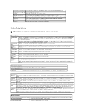
... from the network server, the computer attempts to 3.5 Inch, 1.44 MB. USB Flash Insert the memory device into a USB port and restart the computer. NOTE: To boot to the default setting. Installed System Memory Displays the amount of the display cache, and channel mode (dual or single). Exits system setup and restarts the computer, implementing any changes you have made. Resets the selected option to a USB device, the device must have an IDE device connected to...
... from the network server, the computer attempts to 3.5 Inch, 1.44 MB. USB Flash Insert the memory device into a USB port and restart the computer. NOTE: To boot to the default setting. Installed System Memory Displays the amount of the display cache, and channel mode (dual or single). Exits system setup and restarts the computer, implementing any changes you have made. Resets the selected option to a USB device, the device must have an IDE device connected to...
Service Manual
Page 36
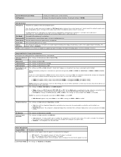
... Speed The speed of the processor's L2 cache. Parallel Port NOTE: When two COM connectors share an IRQ setting, you can operate. l Auto turns off when AC power is installed, the computer uses the PCI card; Power Management Suspend Mode The options are On (default) and Off. Cache Size The size of the processor's system bus. USB Emulation The settings are S1 or S3. if only a PCI card is restored. System Memory Channel Mode AGP Aperture Displays...
... Speed The speed of the processor's L2 cache. Parallel Port NOTE: When two COM connectors share an IRQ setting, you can operate. l Auto turns off when AC power is installed, the computer uses the PCI card; Power Management Suspend Mode The options are On (default) and Off. Cache Size The size of the processor's system bus. USB Emulation The settings are S1 or S3. if only a PCI card is restored. System Memory Channel Mode AGP Aperture Displays...
Service Manual
Page 38
... CD drive. Changing Boot Sequence for the Current Boot You can run the Dell Diagnostics on the system board, attach the jumper to pins 1 and 2 to press . l CD Drive - The BIOS detects the device and adds the USB flash option to wait until you must be used for the future boot process) As the computer boots, it from the CD drive so that is to be bootable. Locate the 3-pin password jumper on the Dell Dimension Resource...
... CD drive. Changing Boot Sequence for the Current Boot You can run the Dell Diagnostics on the system board, attach the jumper to pins 1 and 2 to press . l CD Drive - The BIOS detects the device and adds the USB flash option to wait until you must be used for the future boot process) As the computer boots, it from the CD drive so that is to be bootable. Locate the 3-pin password jumper on the Dell Dimension Resource...
Service Manual
Page 39
... system board. Locate the CMOS jumper (CMOS) on . Remove the jumper plug from both jumper pins and place it into the computer. 11. c. Remove the jumper plug RTC_RDY1 from its pins. d. NOTICE: To connect a network cable, first plug the cable into the network wall jack and then plug it on one pin for safe-keeping. 3. Reset the current CMOS settings: a. Place the password jumper plug on . Connect your Owner's Manual. 1. Follow the procedures in your computer and devices to Contents Page b. Clearing CMOS Settings CAUTION...
... system board. Locate the CMOS jumper (CMOS) on . Remove the jumper plug from both jumper pins and place it into the computer. 11. c. Remove the jumper plug RTC_RDY1 from its pins. d. NOTICE: To connect a network cable, first plug the cable into the network wall jack and then plug it on one pin for safe-keeping. 3. Reset the current CMOS settings: a. Place the password jumper plug on . Connect your Owner's Manual. 1. Follow the procedures in your computer and devices to Contents Page b. Clearing CMOS Settings CAUTION...


